More laddermill / spidermill ideas


I was sat thinking about belt types? This is more commonly know as crochet? I’m demonstrating the small length so you get some idea of texture materials? There another technique encountered as a Viking. take ages and conventionally done by hand as I know no machine that can do it?

Nalbinding. Is very old and maybe the reason knitwear became used to things like crochet or kitting. Because it’s quicker and fastest? I can hand braid even know how to make scoobies.

which can be machine braided? In quantity? Though don’t know who would do them?

You can get Viking knit chain bracelets? Though it rare to see large quantities or huge length? Due to how time consuming it is? I’ve made steel core knit chain in the past?

Don’t know if it would be useful here?

Just a few more loop ideas?

Version 2. Here I assume the kites hang below the loop and only allow them to go down the same side of the ground station as the channel. I also put an angle between the two red pieces, the channel and the protrusion, so that there is only a problem if the kite approaches in between the legs of the V-shape that they make with each other. I didn’t draw the funnel, or other solution for the point where the kite tether attachment enters the channel. Notice the protrusion extends in front of the channel so that the kite tether is guided toward the channel.

This concept, with the multiple smaller pulleys, I think is better than what you normally see where a big wheel is used, as you can make the distance between the two sides of the loop arbitrarily large, like you see with ski-lifts, and the wheel isn’t in the way. And small pulleys are simpler and cheaper than giant wheels. You would still like to use as big a pulley as you can get away with to try to reduce the number of them and with that their friction loss. Bigger pulleys should also be able to handle the possible kite tether pod better and need less clamping pressure.


Sort of what I’d imagine it to look like? Obviously main components not displayed just the c channel.
The oval shape help guild the loop around. There can be concealed pulleys in the top and bottom. But also in the mast structure itself? Like blades of grass swaying in the wind? Blades of the wind? Can be as tall a skyscraper or pocket side? About to affix to a vehicle of outdoor structures? Personally I wasn’t going to make it too complicated?
If anyone else wishes to chime in feel free?
@PierreB @dougselsam @Rodread @AweEnthusiast
It has also occurred to me that the streamer idea?
Looks awfully a lot like?

So potential for and advertising board? With something like rolling type?

I found a helpful drawing

Where we also find someone saying:

“According to an article in The Manchester Evening News:
Delft Technical University is actually going to build one!

(OK, Well that was on Wed, 13 Apr 2005, so…)

(Sorry, tried posting links but they would not display properly in this format for some reason)

1 Like

Even the bbc covered it?

https://youtube.com/@Laddermill
https://twitter.com/kite_power
That’s the team at delft university.
@dougselsam funny you should post that link? I had seen it wondering if it was with the shout?
Mad respect!

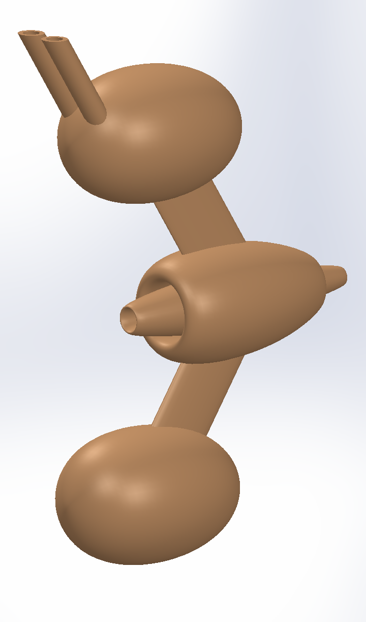
Inside the central ovoid here there are 2 rings that go around the tether that the pod rides on. Also there is some clamping mechanism that clamps the ovoid to the tether when the kite moves downwind and just before it reaches the ground station.

The rest of the assembly is connected to that central ovoid with a bearing that allows the assembly and with that the kite to rotate around the ovoid and the tether, or you leave out the bearing if you decide you don’t want that. The pod needs to be small to be able to go around the pulleys, so extra elements like batteries, electronics and motors go into the other ovoids. You want to preferentially put the weight in the pod instead of in the kite, so you could for example try to fly with two kite tethers like shown here instead of one.

1 Like

Liking the fuel pod and pylon approach. I’d hazard a guess the loop is passing through what look like a jet turbine? If that so? Does that mean its using the incoming airflow? compressing it to fire the loop to distance to max distance? Or is it passing through the tube structure in the top pod?

The first video starts out with the “journalist”(?) “explaining” how modern wind “turbines” are “40 times as efficient” as old fashioned windmills. This indicates that this person a) doesn’t know anything about wind energy, and b) does not understand the meaning of the term “efficiency”. And this is how things really work - people who have no idea what they are talking about get quoted by someone else, etc, until at some point you have legislation being enacted over some offhand comment by someone who is literally a “know-nothing”. He ends by claiming the only thing holding back development of harnessing the wind is the word “alternative”, whereas the actual wind industry is expanding about as fast as you could ever expect any industry to expand, The implication is the only thing holding back harnessing the jet stream is a vocabulary word, whereas the real thing holding back AWE is the inability of anyone to demonstrate a reliable and economical device, with nobody ever having bothered to build even the most rudimentary “laddermill”, for example. Seems like the implication is AWE is just one more “victim” of closed-mindedness, whereas in reality it is the lack of AWE coming through with their promises, to the point that today, wannabe AWE people sit around wondering if maybe human intelligence is incapable of even coming up with such a reliable and economical configuration, but maybe a computer could out-think us and be more creative and/or on-target. So it goes from “we have all the answers” to " we just don;t really have any answers at all.":slight_smile:

Version 2. Now the rotating assembly sits around and behind the inner part so that there is more space inside the inner part for a clamping mechanism. Also there is a lever that the ground station could engage that engages the clamp. Maybe the rotating assembly can engage it as well at the top of the loop.

Version 3. The default state is that strong springs clamp the red part onto the tether. To disengage the clamp, a motor moves the black cylinder forward to engage the lever.

Questions now could be, what does the clamp mechanism look like, and how does the motor move the cylinder.

If we’re dealing with cables? Then lift safety system could be employed?
This example uses wedges. To slowly clamp the tethers.
If It was completely magnetic? then an induction coils could be used to slow it down? This can be automated on motor overspeeding? use some snagging system to power by the loops momentum? To bring thing to a halt? This would be useful on other awes systems where long cables/tethers are involved?

It might be also noting the potential for ware on all components? Especially on the tethers with repeated Engagement of safety system. The pulleys will also be a point of high ware. The only issue I can see if if you have really long tether? stopping in flight the whiplash potential will be quite high? No point have half a tonne dropping on your head?

If I understand what your proposing? the red section is free to rotate? The black ring acts as the engagement mech?
Then something like zoom ball? Would work?

I had one as a kid I be damned if I know where that purple thing went? Our might have rotated? The one we have look an lot like the nerf ball? It usually joined in two parts? So can be assembled preflight?

Ingenious Bombul-Bruticus.stl (201.3 KB)
So I was sat thinking if you had a solid wind body with an opening would it work this is a rough working still a few kinks to figure out? But the idea is to have to loop doo something like a treadmill? If someone was feeling brave enough they could retrofit some on the largest aircraft we have for the task?
The loo would run through the mouth off the solid body? Running over as many rollers as possible? It currently quite a rough stl. But I can improve on that? Mainly a visual for now? The streamer would run through the mouth? Can be as long as required? Even stacked up in a kite train if required? Flying letter boxes?


Not quite thunderbird 2 but Getting close?
@PierreB @Rodread @dougselsam @AweEnthusiast @tallakt @Windy_Skies
In theory the size is only limited by material capabilities?
Co flow jets can be employed in numbers of ways? Even as an means to draw a more air in? For instance

Co flow model like this With ion components? Might help?
Would need to be custom fit? But totally doable! With such a design there is ewicon possibilities? Though more weight and more cost!

Just a question of how large you would want one?

A bit of a different idea, with the clamp you can either just clamp the tether between some flat or curved surfaces, or you could use wheels that you could brake (which could perhaps be useful for other AWES where you might want to use a similar mechanism but instead use wheels where you brake the wheels if you want more control over its speed), but if you are going to use wheels you might as well keep the loop static and put a generator in the pod, and have the generator in it generate energy while going downwind, release the wheels while you glide upwind, and release the stored energy at the ground station. Or some different combination where you take advantage of the potential energy of the kite and pod.

Or can you? How is this going to interact with the loop attachment points on the ground station?

One thing I don’t understand is the strength of the rope for the loop that you then need. Is it going to be the same or not? Is it going to wear more or not?


Imagine what would happen if you made that and attached a string to the mouth. Would it make a good kite then? Where should you attach the string? You have to start from a good kite design. This topic is not really about kite design.

Multi point bridal can attach to the aerofoils? leaving room for the streamer to run through the mouth? It can with not too much modifications? run smoothly underneath the lower part of the wing body? Then back through the mouth in a continuous loop? I’m aware of ovoid wings and rings wings


They do exist? Makani was just one example of a solid body kite.
For example?
I might be able to give you some ideas on braking strength of various grades of paracord?

Usually the more strands it has the more strength? Climbing rope is usually rated in multiple of bodyweight? Because it got to get a man and his gear up hill?

I thought the topic was to see if there were things that could be done? to help ladder mill and spider mills along? That might even mean exploring design options?

In variants 2&3’s case?
2, can be a triangular bridal connecting it to the ground station?
3. Can have the cables running up to the multipoint bridal ?

Any oh? just trying to provide as many visual cues as possible to put the point across?

You didn’t answer my question.

What would happen?

I’m irritated with you.

You don’t seem to understand how laddermills work or how wind energy works or what I am talking about. Instead of trying to learn more, despite me asking you repeatedly, you are here doing this. You have to understand a thing before you can improve on a thing.

The picture you show here is essentially an airplane, with you attaching a string to the tip of the nose of that airplane. Now go try to fly that airplane as a kite without starting the motor. It will stay on the ground. Now put 10 of those in a row, nose to tail, and they will still stay on the ground.

If you want something heavy like an airplane to fly like a kite, it has to fly in circles or in a figure eight pattern. It has to fly very quickly to generate enough lift to lift itself off the ground and pull on the tether to turn the generator. The lift goes up at the square of the speed, so if the airplane goes 7 times as fast, it generates 49 times as much lift.

When you want to fly an airplane like a kite, you attach the tether to the center of lift of the airplane, I think, not the nose.

My pod above is an attempt to connect this quickly flying airplane or kite to the loop of the laddermill (spidermill now).

My thinking was if the aspect ratio was right you wouldn’t need to fly in circles? The bridle only need to be rigged in a forward direction much like you you see in surf kites for it work? Bridal attaches to the both wings. Therefore there no need for to attach to the nose. just a few point on the leading edges.

What else would you like me to say? I did say I was a roughing out of a idea I had?

I could see how you would attach. Why I mentioned .

Not trying to irritate you. I was being speculative on potential shapes.
The bridal can attach to the leading edge?
It may require a launch system? Depending on size and scale? It would need much pitch control 5% pitch would enough to generate lift. I’m thinking catapults?

The airbus a380 is a good example of lift ratios. That where my thinking was?

I’m not doing this to wind people up? Sorry if I got you goat? Wasn’t what I was aiming at? I was only suggesting on way to loop could warp around?

Hi everyone, just thought I’d inject a bit about the laddermill concept as it related to the SuperTurbine™ concept. They are really two versi0ons of the same concept. Laddermill could be said to approach a Darrieus version of a SuperTurbine™. Alternatively we could say laddermill started out as a “cross-axis” (broader category of “vertical-axis”) machine, but as it matured in my mind, way back in the 1970’s, it morphed itself into more of an aligned-axis (broader category containing what we normally call “horizontal-axis”) machine. In other words, the idea morphed toward what is known to work better, based on my growing exposure to more knowledge of wind energy as it really works. So what I’m saying is the two concepts: (Laddermill and SuperTurbine™) could be said to represent alternative aspects of the same basic configuration, which is a ground-gen-based, downwind-extending, upward-slanting, lift-based, continuous-operation, wind energy machine with airfoils completing a repeated closed-loop circuit, using as much lift, as opposed to drag, as possible . I would say these are the two simplest and most basic steady-state airborne wind energy concepts. To me, they invent themselves, I’m just the channel through which they arrived. And by the way I think there has been a very limited version of lederhosen - er um I mean “laddermill” presented at wind energy trade shows. If memory serves, I think they appeared in what I call “the comedy section” of the show where you typically see tabletop models of vertical-axis machines using, say, maglev bearings, powered by forced air from a household fan. In the case of laddermill, I think I remember seeing a version that fits inside a long, flat box, like a foosball table, but with an open back, oriented more upright, with rollers at the top and bottom, kind of like a solar panel, basically a belt of up-and-down rotating vertical blinds. I don’t know, maybe I’m just hallucinating, but I could swear I’ve seen something like that. And by the way, I can see severe problems with that exact version, as in, there were some strong performance-limiting issues with the exact model I’m referring to.

@dougselsam
image
A quick search online? This came up? Doubt it the one your talking about?
Any chance you have a pic of the foosball version?
Central roller in the Centre?
It would Seem for Comparison sake this would be nothing new?
My Chain of thought is in the 50s? only another 75 years to catch up on? Closing but a long way to go!

Nope! I don’t think you were hallucinating? May end up looking like a roller blind set? But a continuous belt?

At the moment I don’t see a credible way to launch the kites, if you’re not doing rotary launch, as the top of the loop seems to get in the way if you try to launch while circling around the tether. Maybe you could fly a figure of eight pattern instead, but let’s ignore that for now.

So let’s instead think about a rotary launch. Instead of this installation from my quote above that first launches the kites separately, now the kites (pods) sit on, or on the ends of, two arms.

Before the arms start rotating you release the clamps in all the pods, except the topmost one on each arm, so that the topmost kite on each arm can start pulling on the loop.

Now the pods have, beside the clamp, also a motor or spring in them that allows them to extend and retract a (single now) tether to the kite, and a brake that can stop this extending. This brake is engaged in all but the topmost pods. Result is that the topmost pair of kites can start pulling on the loop, and their tethers can start extending. The other pods stay on the arms as the loop just goes through them. There is also a stopper on each arm that keeps the other pods on the arms. When you want to launch a next pair of kites the stopper lets them through.

So, you see the arms start to rotate, the tethers of the topmost pair of kites extend, you release the brake of the drum and the topmost kites start pulling the loop into the air. Repeat for all kites and until the drum is empty and disengaged from the loop. Then you change operation mode where perhaps you could stop the rotation of the arms, or not, and you start the rope drive.

You could decide to keep the kites high in the air by periodically changing the direction of the rope drive, I think, if that doesn’t collapse the top of the loop. Then you could also just use a lifter kite (train), making everything easier.

Or have this lifter kite, but instead only have kites on one side of the loop. The other side of the loop is empty and goes down again, but now through the pods. You’d have a spidermill that from a distance looks like a single tether with kites circling around it, perhaps in opposite directions to limit twist. Maybe you could have the kites go up and down out of sync, like stop-and-go traffic, to limit the size of lifter needed.

Or same principle and just let the empty side be much slacker and longer than the other side so that it doesn’t interfere with the kites. That should be possible I think if you increase the number of wraps around the pulleys or clamp pulleys together to prevent slippage.