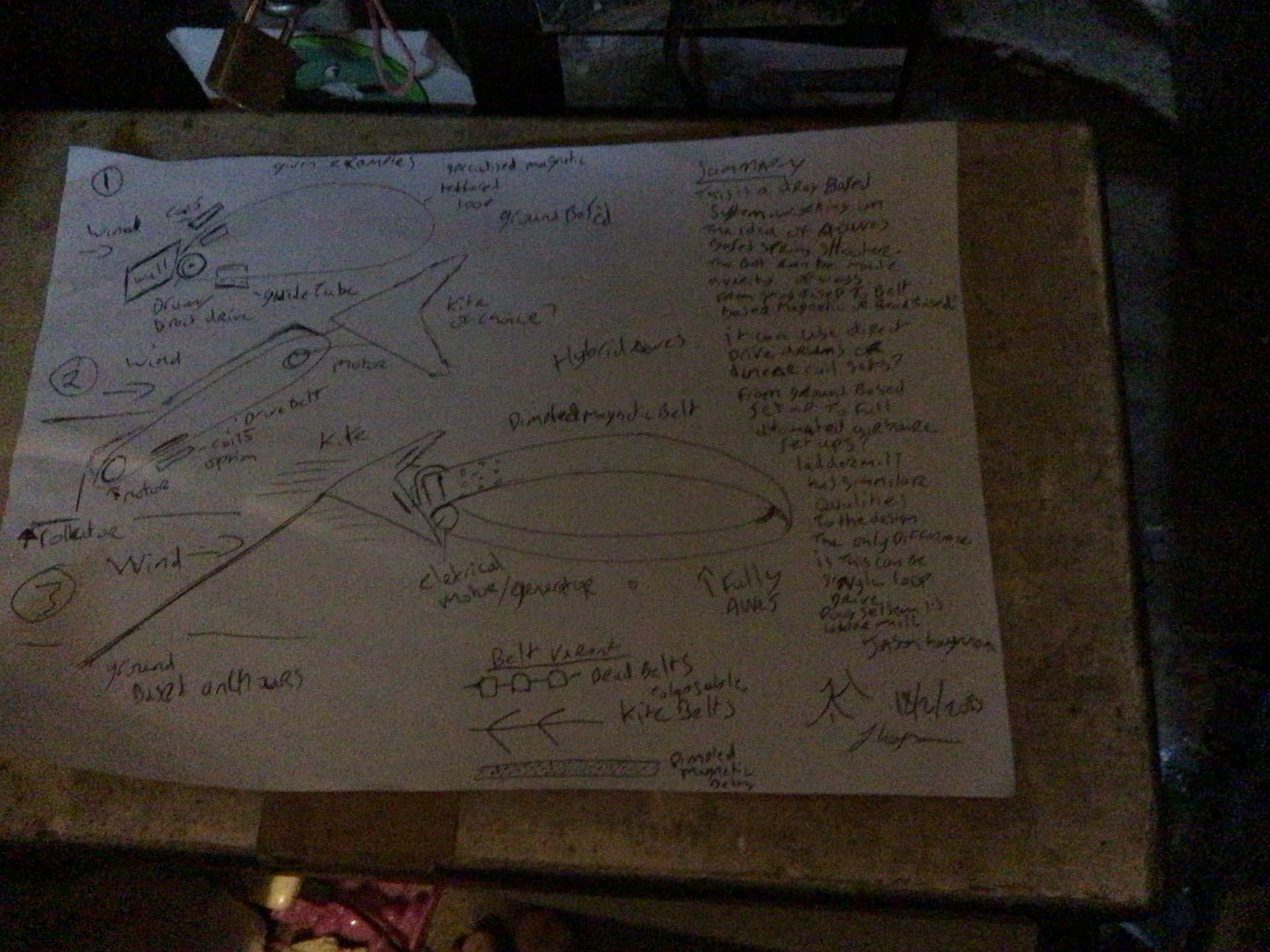
Quickly scribble this down this morning.
Just to give a visual?
With some idea where it could go?
Version 3. the belt could act like a streamer? Adding stability? Operation can be at altitude? Use coflow jest as a feature?
Honestly the list is endless?
@PierreB @Rodread @Windy_Skies @dougselsam @AweEnthusiast.
1 Like
There are multiple glaring issues with that, the manual launch and landing, the giant wheel in the sky, the gigantic lifter kite needed, and it being drag based, but the main idea of the two kite attachments points is not a bad start I think. I think the ascending side will have a higher tension so that should be on top, but then perhaps you’d get (more) interference with the wheels.
One variation to make it crosswind is to instead use a single loop and let the kite swivel around the loop tether.
I do kind of like the streamer idea. For now you can replace the lifter kite (or lifter kite train) with a tower, and get a 0 degree elevation angle, no kite control needed, laddermill. The con is that you need either airgen or a two stage rope drive.
You can combine it with Doug’s idea of attaching kites to the loop in such a way that they catch the wind in one direction and don’t in the other. And there is also my idea of then also letting the kites circle around the loop tether.
I think you need a funnel that looks like a C from the top around the pulleys to prevent the kites getting stuck in the pulleys. And better to have more pulleys clamping on each other to reduce pressure needed.
You only need a tower, some pulleys, a loop of string, and some kites, so I think this is something anyone should be able to experiment with.
The streamer as it is now is rubbish. The things I would have liked you to find for yourself earlier is that you need to increase the frontal area to catch more wind, and that drag based anything is a bad idea, for example, but you need to experience that for yourself or see videos of it in action to really understand that.
Here is an idea:
A plywood base, on that say 6 pulleys in a semicircle. Each original pulley, or a fraction of them, has another pulley pressed against it, and a generator attached to it. Make a box around this with a channel cut out (rounded hemi-dodecagon) that goes above the path of the loop. Where the loop enters the box there is a C-shaped funnel (or something like a combination of that with the tip of a syringe needle with a slit along the shortest length of it) that directs the kite tether arm to the channel. This syringe needle tip / C-shaped funnel combo and the pod and the kite tether arm work together to orient the kite tether correctly and prevent the kite getting stuck in the box. The pod can have an arm attached to it so that the kite tether doesn’t need to go into the box, and to decrease the possibility of the kite tether getting wrapped around the rope drive.
But what if the kite wants to go along the opposite side from the kite tether arm along the box. To accommodate that I think the box needs to not be rectangular, but have this same rounded hemi-dodecagonal shape cut out from one side so the kite tether can more easily be dragged along this, even if the length of it is low.
You can work on this before thinking about towers and kites.
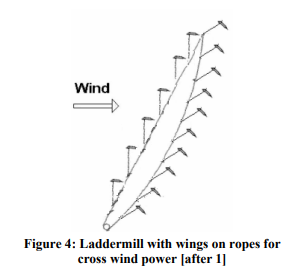
A crosswind version of Laddermill was studied. I remember that its name was “Spidermill” but it does not look to be an official name. Laddermill - #8 by PierreB.
The pdf is available on Comparison of concepts for high-altitude wind energy generation with ground based generator | TU Delft Repositories. I reproduced the Figure 4:
@Windy_Skies it might seam a little strange to some people? but modify a hand towel dispensers?

As you mentioned box shaped units?
Should be easy to make it as long and you like?
Also
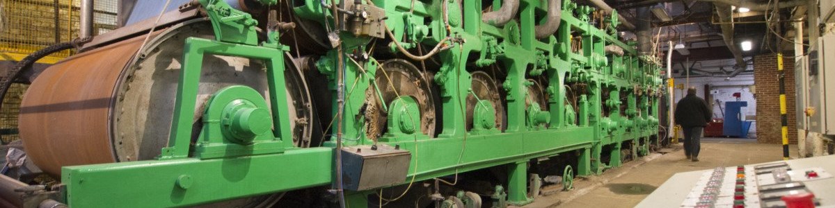
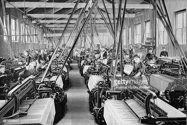
What you described sounds much like a paper mill set up? If it loops around multiple rollers? Inside the box unit? This could them have complementary gears? To gear up and gear down what the wind can probably provide? This version would be on the heavy side?
Total doable? Wheel barrow wheels? Spindles? Even plywood preforms?
@PierreB I can see the point your making. Self opening pocket attached to the belt would be good? As it reminds me of
But for wind applications? There are similarities to laddermill? The self opening bucket would help out a lot. There will be need for spool flanges but that easy to to? Heck I could to turn them out of wood on a pole lathe? I’d even sat thinking I could stick a few bath towels together? For the trial run before adding motors? To reinforce the towel you can’t stitch paracord banding? Much like the steel mech in car tyres? Might annoy the wives if the lovely new towel go missing?
The major issue that could be encountered is when the weather goes full tempest? Rain stops play? How dose rain slow it’s performance? Might be able to get round that with a hydrophobic coating? That something that will need to be bridged when it comes to it?
@Rodread @dougselsam any ideas?
As for a returning c section that can be as simple as 1*4 boards? If available?
[quote=“Windy_Skies, post:751, topic:1610”]
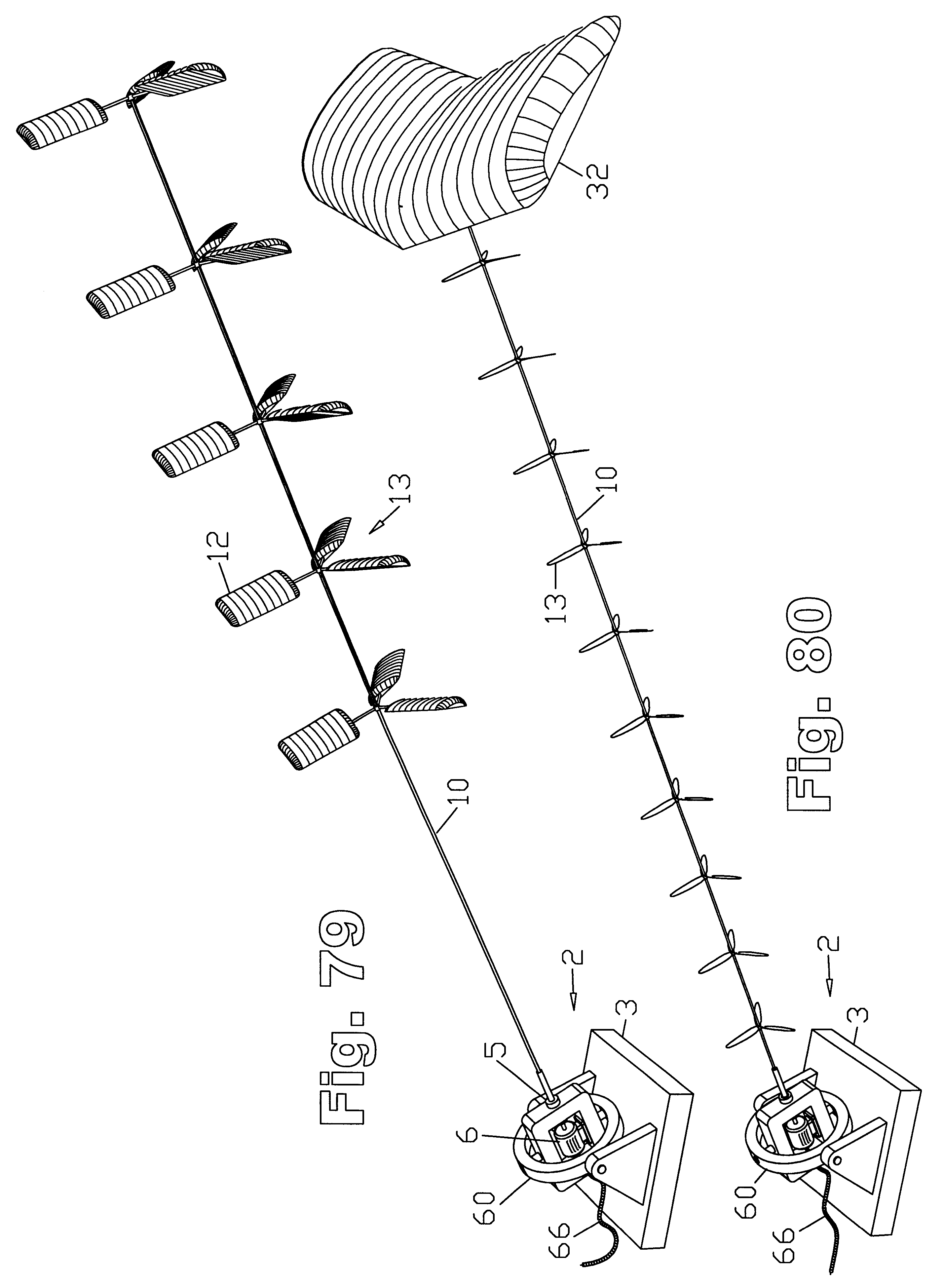
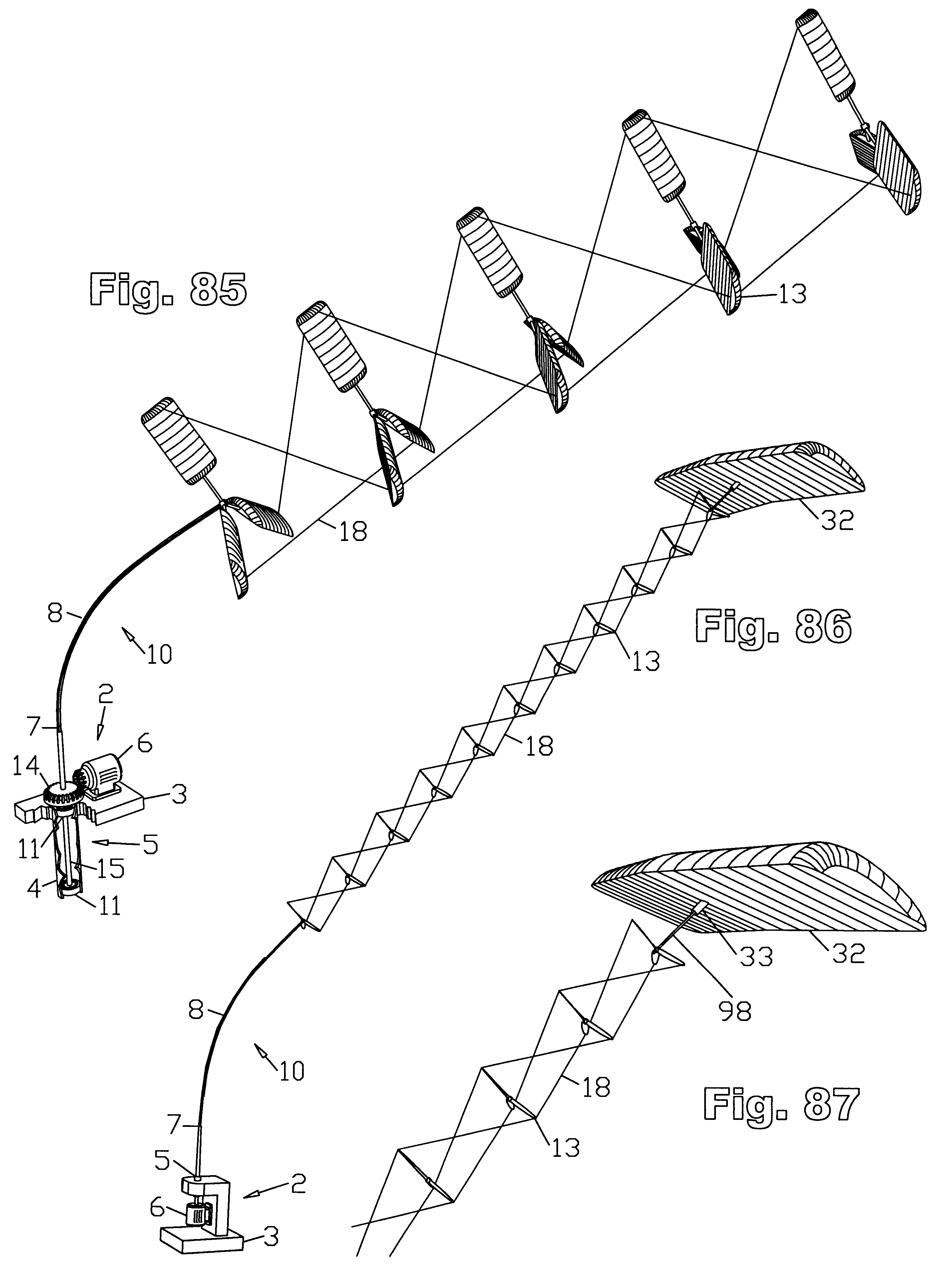
This was an attempt, by me as a mere teenager, with no existing wind industry, which I was already telling everyone was in our future, due to touring the Niagara Falls Hydroelectric plant and being told it powered a good portion of New York State, including our house 70 miles away, and having sailed boats, so I knew the power was there, and with a background in making and flying a lot of kites as a kid.
I knew someday the world would stumble with confusion into an AWE frenzy, with a lot of attempts at it, and wanted to at least document that whenever some wannabe genius thought of by then, I could prove I had already thought of it decades ahead of them as a mere lad. This single early drawing was not designed to be a “final answer”, so much as showing a simple example of a configuration that could actually work, with nobody else even thinking about AWE at that time. I just did not want the future people to think they were the first to think up such a simple device.
Apparently you don’t really understand what you are looking at.
The upward-traveling side exposes each sail to full wind resistance, pushing downwind, away from the wheel. Then as the sails climb, their angle of attack changes until they are sailing upward using some lift. As they round the top, the sails are in full lift mode, which serves to elevate the sails and cables on the downward trip, while presenting very little downwind force, so the downwind lines remain taut as the sails are pulled downward. Since the sails are flying downward like a glider at that point, they are prevented from contacting the upward-traveling side. This same dynamic applies to the version cleverly called “laddermill”, which I had predicted would emerge decades later. A million simple variants are possible. So far nobody has ever even tried to build a single one.
Please don’t mistake every detail in this one-off hand-drawing by a teenager as encompassing every variant I had in mind. It was just an example, so I would have something to show the world, so at some future time, they would realize I had been light-years ahead of anything they could think of, decades later.
By 1980, I had read my first book on wind turbine design, ordered from the U.S. Government Printing Office. From that I got a quick education. It was not a very thick book, but it contained all known designs and their advantages, disadvantages, and operating characteristics.
One of the most important was lift versus drag, and that any device with working surfaces that traveled downwind, then upwind, tended toward being a “drag device”, whereas a device with working surfaces traveling 100% crosswind, and holding their ground against downwind travel, tended more toward being a “lift-based” device, which offered much higher speed and efficiency, therefore, while I still saw the advantages of my original “aerial tramway”, I thought “SuperTurbine™” represented a probable improvement on the concept.
From there I had pretty much decided that this new, yet similar device, that could “hold its ground” against downwind travel, using 100% crosswind travel was the answer, rather than traveling downwind, then upwind, which was more drag-oriented, so my mind turned toward various versions of SuperTurbine™ - simply taking the best existing wind turbine design, and stretching it out at an angle to the windflow to expose each rotor to its own fresh wind flow.
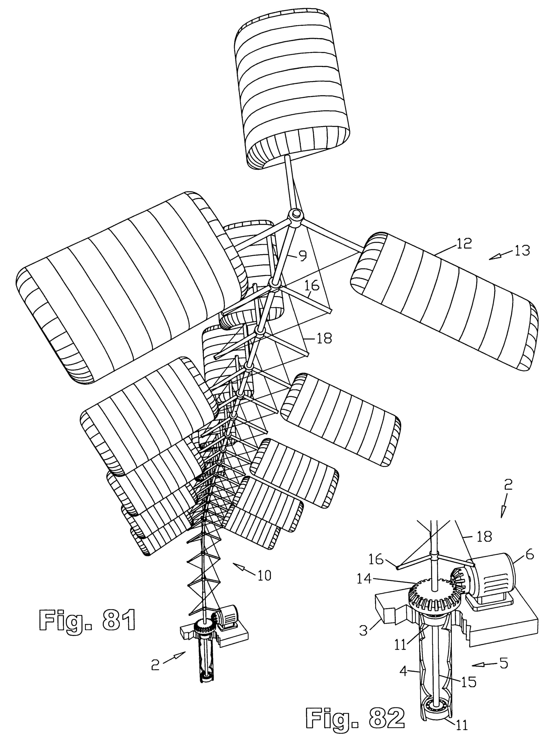
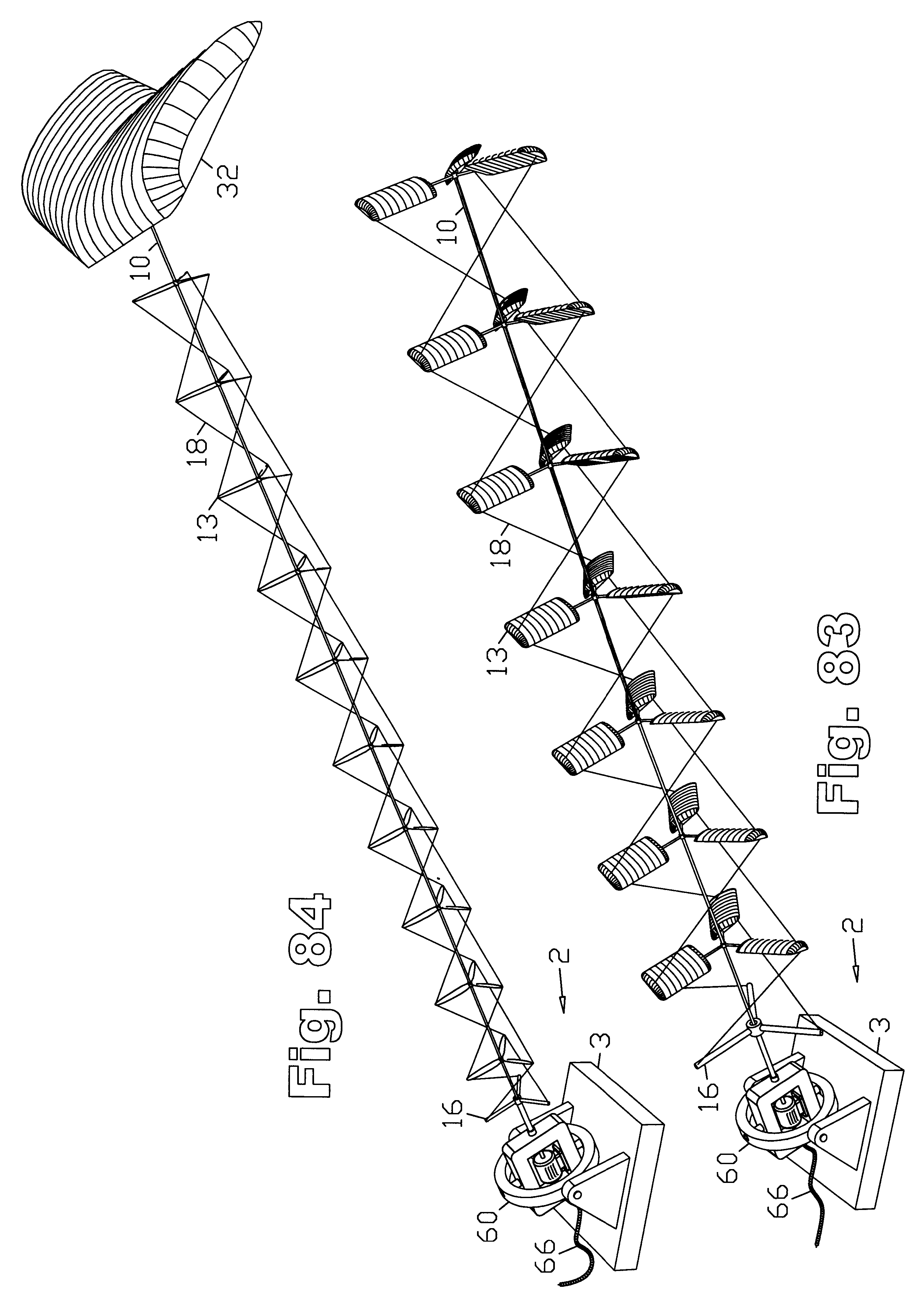
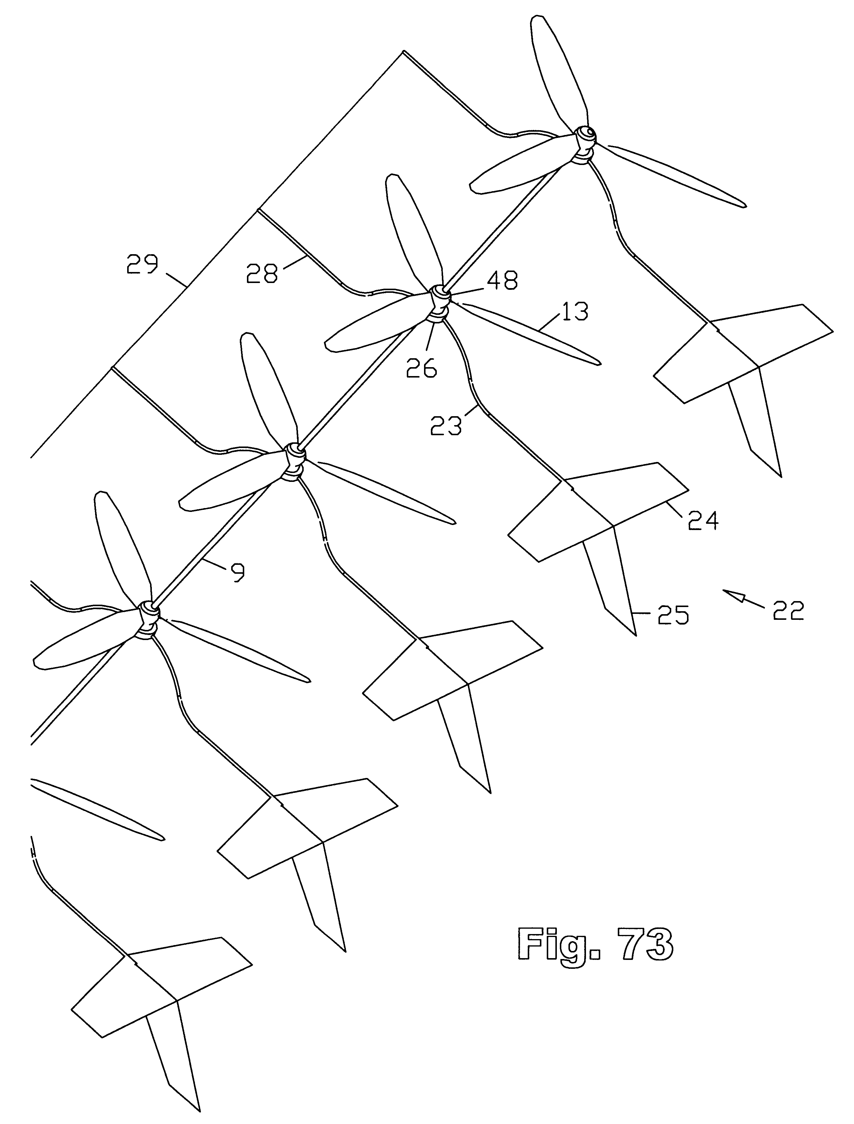
One major advantage of the SuperTurbine™ concept for AWE, was the angle of the driveshaft necessary to expose each rotor to fresh airflow, neatly matched a typical angle of a kite tether. So it seemed like a fortunate favorable match of operating characteristics, with the upward angle of the “driveshaft-tether” served three purposes simultaneously:
- Elevating the apparatus in the manner of a kite tether, at a similar angle;
- Placing each rotor at an angle that helped to elevate itself and the entire structure;
- Allowing fresh wind to reach each rotor.
By 1981, I was a Physics Major at University of California at Irvine, and with the world’s first windfarms suddenly appearing in nearby Tehachapi, we were learning how wind turbine rotors worked, and how to derive the Betz coefficient on-paper, from a strictly theoretical standpoint.
In response, I was showing my further drawings of SuperTurbine™ to my Fluid Mechanics Professor, and was kind of surprised that he did not quite seem to appreciate the significance of my way to multiply the power of a wind turbine to an almost unlimited extent by stretching it out into a third dimension.
This I saw as fortunate, realizing it would be unlikely that anyone else could even understand what I was thinking, so I was probably at the forefront of a new paradigm in wind energy, from several angles. I realized I was on my own and would have the opportunity to develop the idea myself, which I subsequently did.
So I’m glad I had the sense to document my initial ideas way back in the 1970’s, so decades later, I would be able to show that I was at the forefront of early thinking about improved wind turbines and AWE. It would be nice if I were given a little more credit for my ORIGINAL thinking, which preceded most other early awakenings to the possibilities of multi-rotor wind turbines especially, but also to AWE in general.
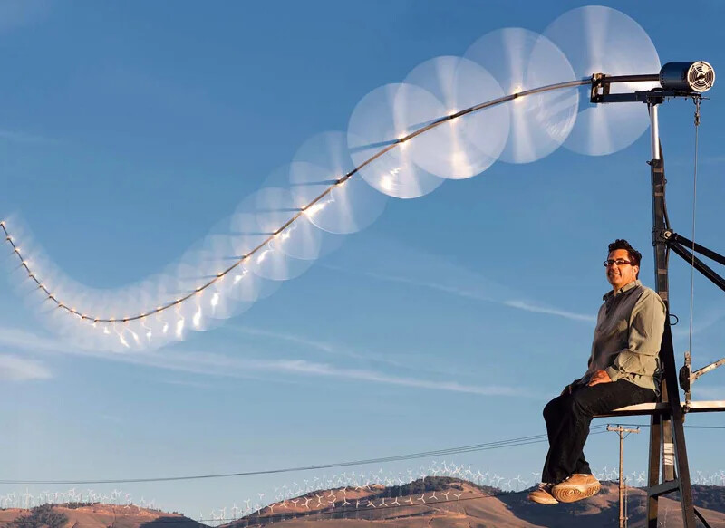
I was one of the founders of the movement, and along with the Makani effort, my early protoytypes helped place AWE “on the map”, ushering in today’s annual AWE World Conferences, which happened at least partially in response to my having already won a Popular Science Invention of the Year in May, 2008, a year before the first World AWE Conference.
LINKS:


So of the three AWE “players” at that time, me, Makani, and Joby, I was the only one who brought a working demo to the conference, and it flew unattended, even overnight, for three (3) days, operating without requiring any computers or human attention, charging a bank of batteries inside the support vehicle.
This first AWE Conference was fun, but it was also apparent that most of the people attending were pretty much clueless about wind energy. There were a few people who knew a lot about flying kites, but I could tell they were incapable of comprehending wind energy, which remains true to this day. I could see most of their ideas and proposed approaches were scatterbrained, untargeted, and incomplete. I surmised that it would be quite some time before, having tried everything else, people would begin to realize that some version of SuperTurbine™ offered some of the best possibilities of success.
Now that so many other ideas have failed, it’s encouraging to see things slowly shifting over toward SuperTurbine™, exploring some of the myriad possibilities the concept offers. I look at it as “The SuperTurbine Army”. Someday, as the other ideas fall by the wayside, it may be recognized that I was one of the founders of airborne wind energy, or maybe, if none of the other approaches work out at all, The Father of Airborne Wind Energy.
2 Likes
You’re right, I didn’t. Thanks for the correction and the comment. You’ve done and made some nice things, which is difficult, and which have also influenced my thinking.
1 Like
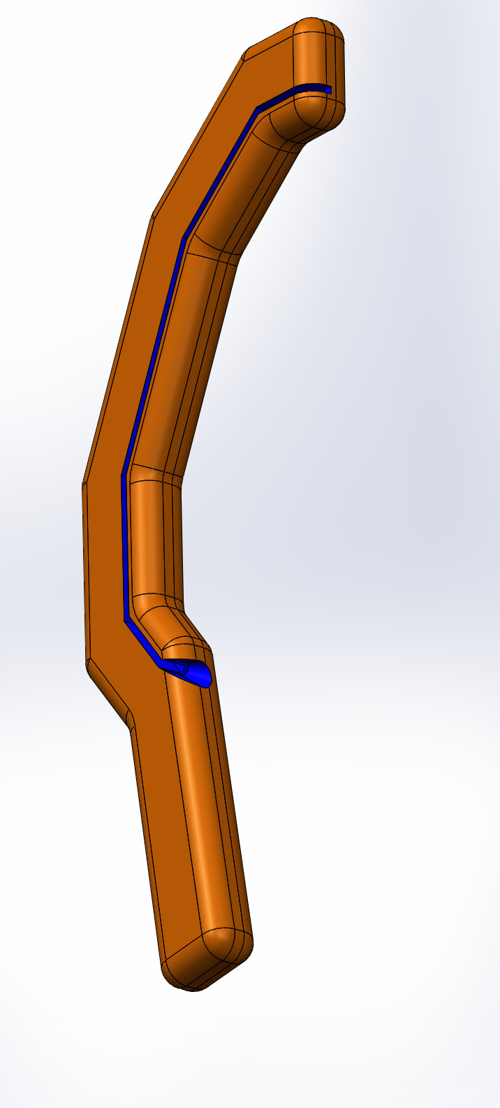
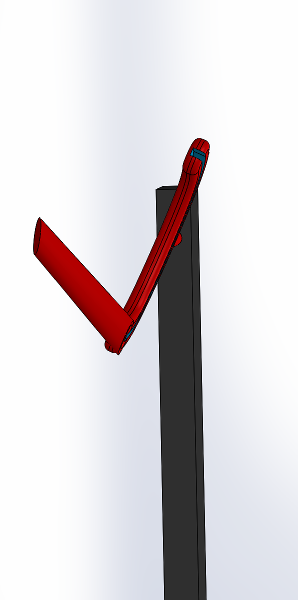
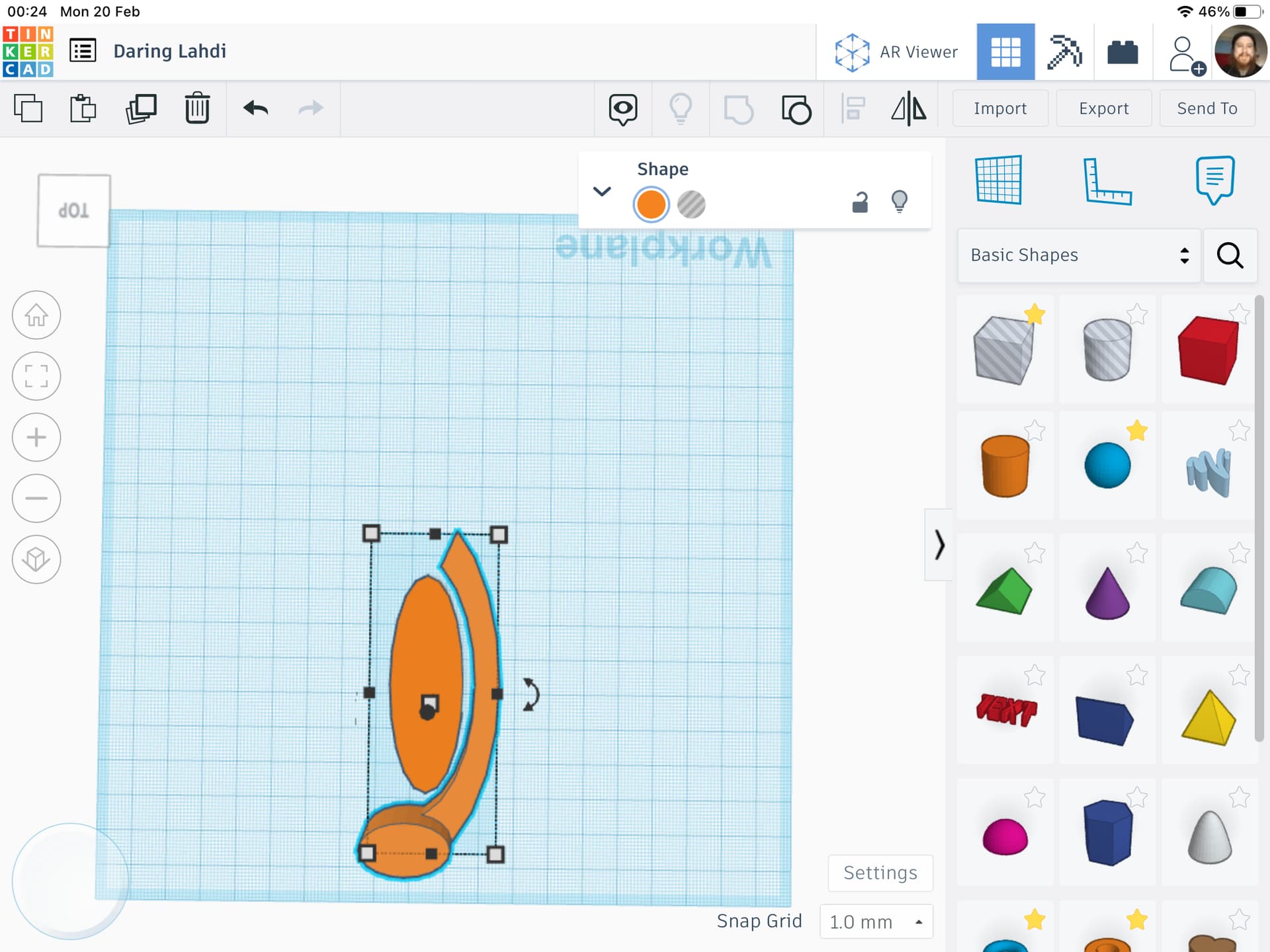
So something like this perhaps, where the shape of the funnel is probably wrong, as now the arm for the kite tether will just run into it instead of being guided by it. The pulleys, inside, are not pictured. The extra protrusion is to prevent the kite slipping behind the object and getting stuck.
1 Like
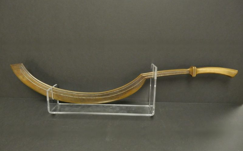
Yes, it rather khopesh shaped. which lead me into making another suggestion. The outside edge can be blade shaped? If you were to take that route?
I can see that It make some sense to do things this way.
With the belts/tethers safely enclosed there’s less risk of injury to the operator. Due to it being a belt guarded system. I had thought if anyone was to take the multiple pulley approach to thing? You could have simple contact wheels
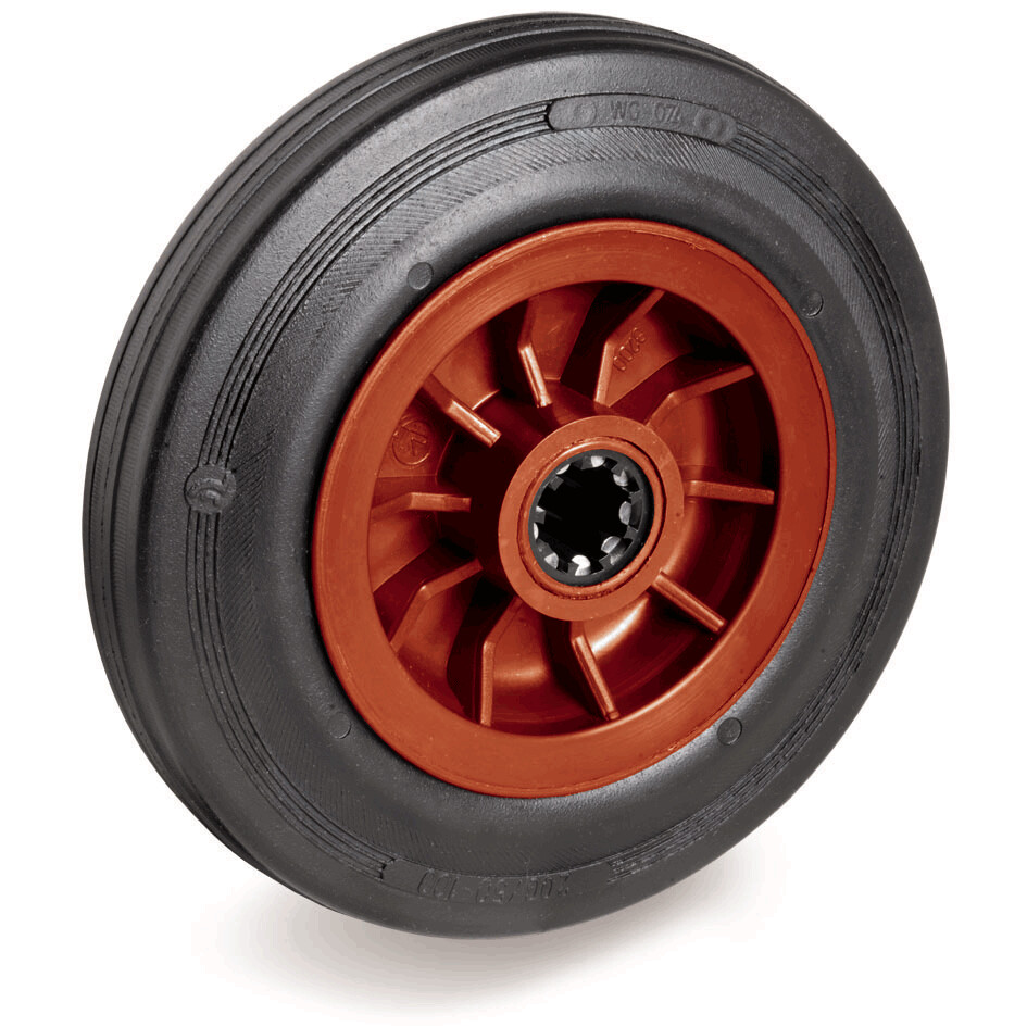
Cheap and readily available?
You can have something that just runs past the top edge or goes in an s pattern along the arc? Weaving in and out? Depends on scale? Will depend on size and radius of the outermost edge. As torque is needed ? the further the edge is from the Centre the more torque can be applied. The pulling can have a simple self centring crown to it? Or be as simple a by cycle wheel? If taking the khopesh route? Then not only has it found a name? It’s found easy of construction and scaling abilities. You could imagine a few of these stuck in the ground? As tall as current wind inferstructure? Just depends how many idle wheels will be needed?
I imagine something like a band saw set up?

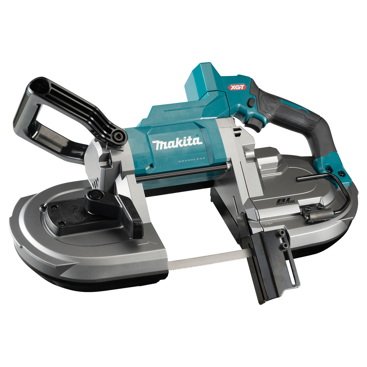
Both modifiable? both very easy to replicate?
I’d imagine the tethers coming out the tip? Then return near the protruding part/ handle?
I was going it be simple and just have a half pipe shape inside a box? Current down on build time and assembly? But I do like the idea of it looking knife shape! Also leave it open to vortex modifiers and vortex drivers? Especially near the tip and exit points? Would make for some funky futurist architecture? All it can be self aligning much like the weather vanes of old? Even could have it looking like a rooster? The chickens come home to roost?
Might be one way of upgrading the existing infer structure? With a enlarged swept area?
There are place which we could take a leaf out of?
As the engineering is already there to take advantage of?
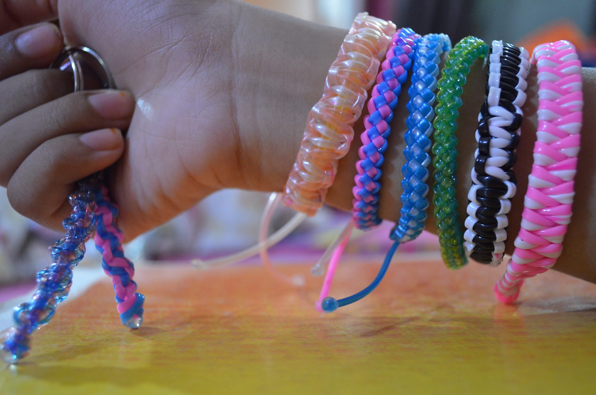
I like the design potential! Real fancy string shooter!
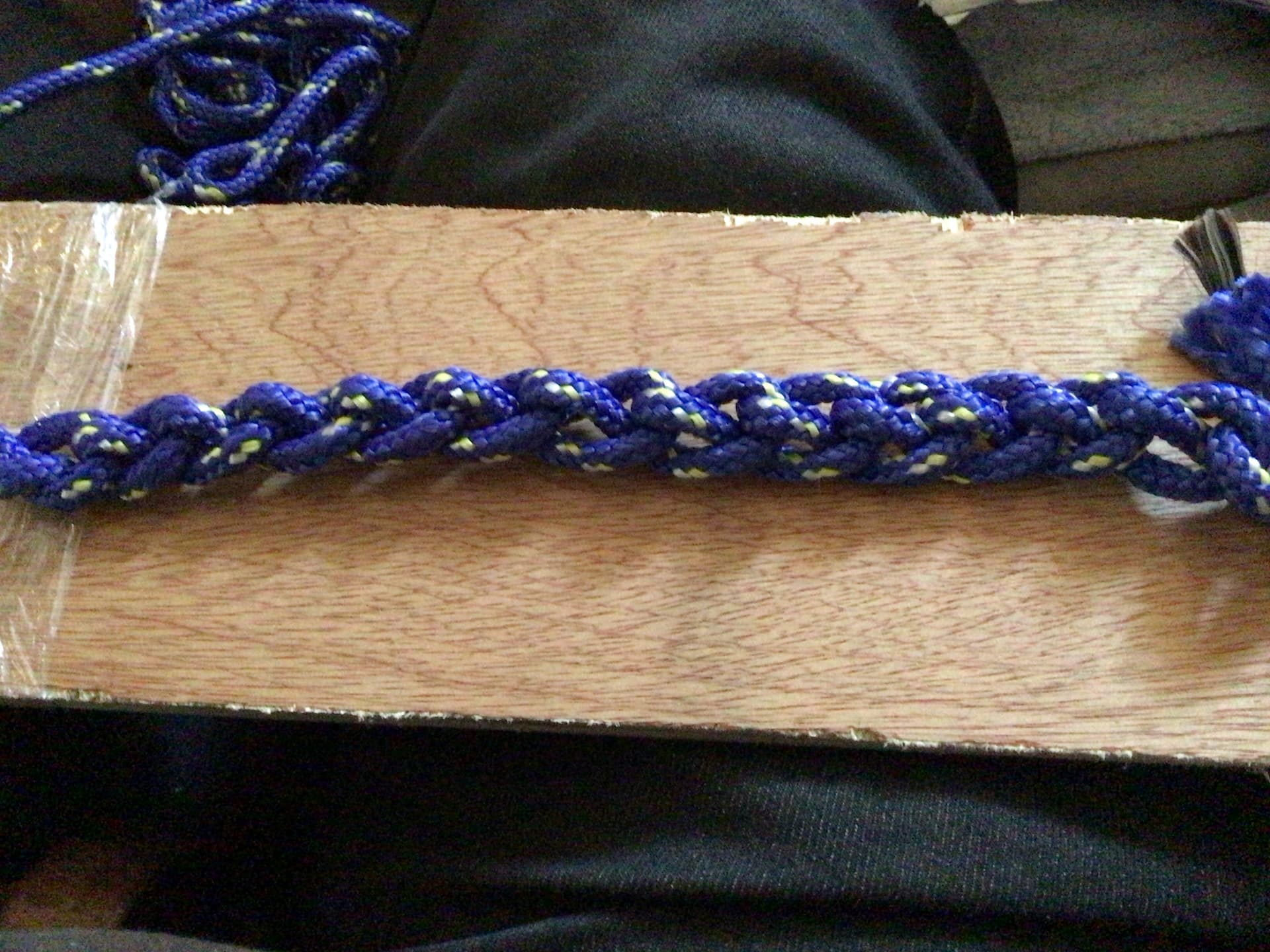
I was sat thinking about belt types? This is more commonly know as crochet? I’m demonstrating the small length so you get some idea of texture materials? There another technique encountered as a Viking. take ages and conventionally done by hand as I know no machine that can do it?

Nalbinding. Is very old and maybe the reason knitwear became used to things like crochet or kitting. Because it’s quicker and fastest? I can hand braid even know how to make scoobies.
You can get Viking knit chain bracelets? Though it rare to see large quantities or huge length? Due to how time consuming it is? I’ve made steel core knit chain in the past?

Don’t know if it would be useful here?
Just a few more loop ideas?
Version 2. Here I assume the kites hang below the loop and only allow them to go down the same side of the ground station as the channel. I also put an angle between the two red pieces, the channel and the protrusion, so that there is only a problem if the kite approaches in between the legs of the V-shape that they make with each other. I didn’t draw the funnel, or other solution for the point where the kite tether attachment enters the channel. Notice the protrusion extends in front of the channel so that the kite tether is guided toward the channel.
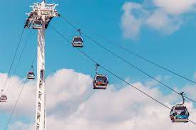
This concept, with the multiple smaller pulleys, I think is better than what you normally see where a big wheel is used, as you can make the distance between the two sides of the loop arbitrarily large, like you see with ski-lifts, and the wheel isn’t in the way. And small pulleys are simpler and cheaper than giant wheels. You would still like to use as big a pulley as you can get away with to try to reduce the number of them and with that their friction loss. Bigger pulleys should also be able to handle the possible kite tether pod better and need less clamping pressure.
Sort of what I’d imagine it to look like? Obviously main components not displayed just the c channel.
The oval shape help guild the loop around. There can be concealed pulleys in the top and bottom. But also in the mast structure itself? Like blades of grass swaying in the wind? Blades of the wind? Can be as tall a skyscraper or pocket side? About to affix to a vehicle of outdoor structures? Personally I wasn’t going to make it too complicated?
If anyone else wishes to chime in feel free?
@PierreB @dougselsam @Rodread @AweEnthusiast
It has also occurred to me that the streamer idea?
Looks awfully a lot like?

So potential for and advertising board? With something like rolling type?
I found a helpful drawing
Where we also find someone saying:
“According to an article in The Manchester Evening News:
Delft Technical University is actually going to build one!”
(OK, Well that was on Wed, 13 Apr 2005, so…)
(Sorry, tried posting links but they would not display properly in this format for some reason)
1 Like
Even the bbc covered it?
")
https://youtube.com/@Laddermill
https://twitter.com/kite_power
That’s the team at delft university.
@dougselsam funny you should post that link? I had seen it wondering if it was with the shout?
Mad respect!
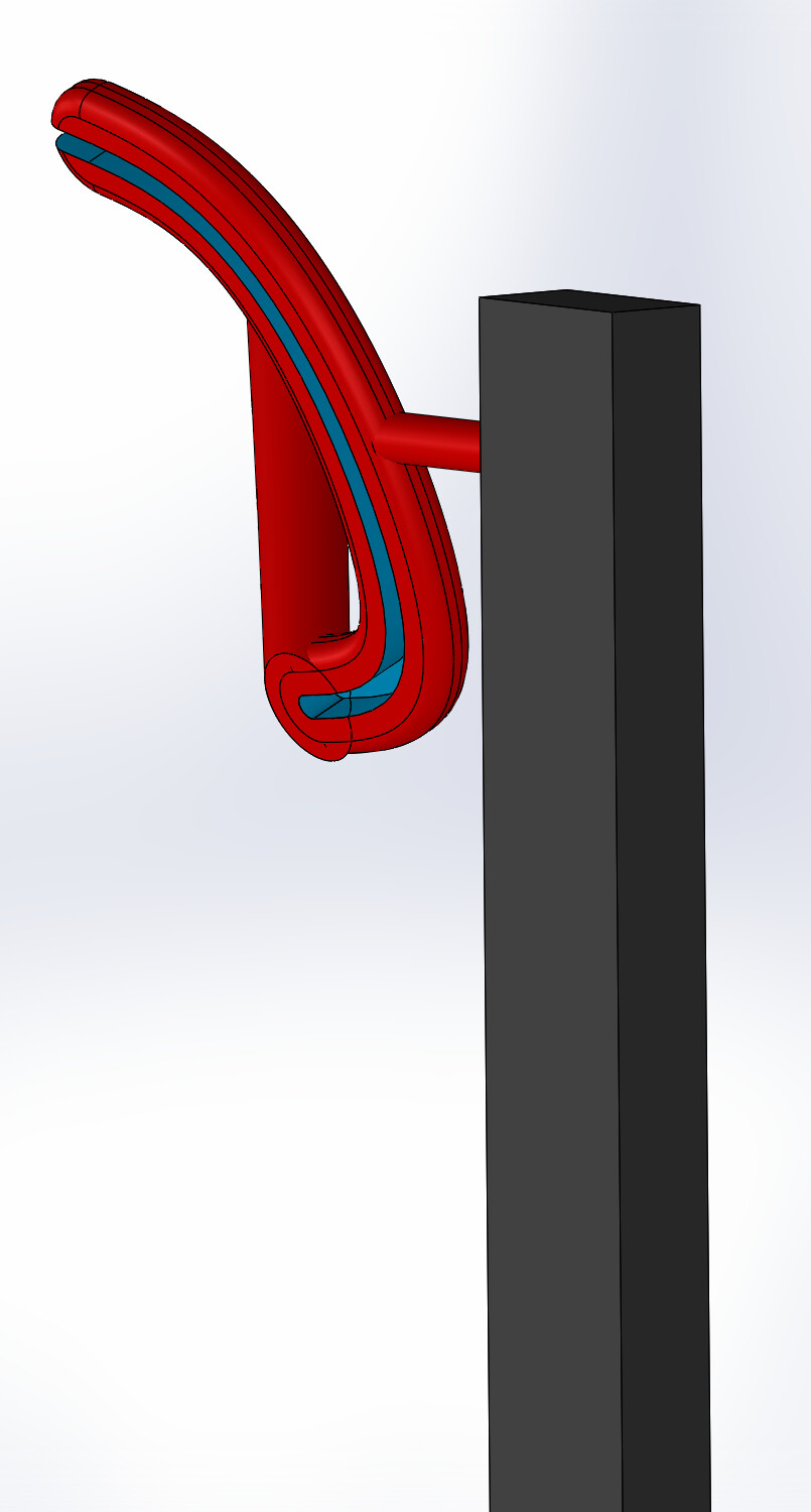
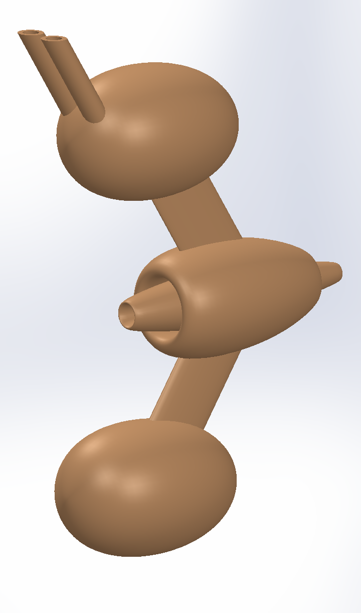
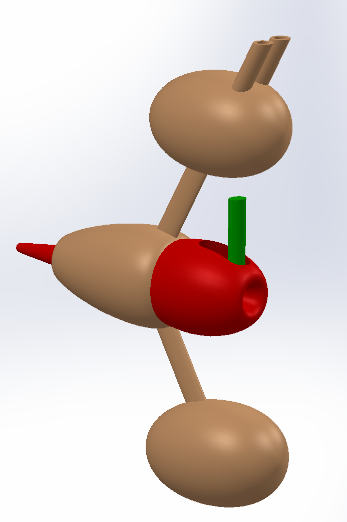
Inside the central ovoid here there are 2 rings that go around the tether that the pod rides on. Also there is some clamping mechanism that clamps the ovoid to the tether when the kite moves downwind and just before it reaches the ground station.
The rest of the assembly is connected to that central ovoid with a bearing that allows the assembly and with that the kite to rotate around the ovoid and the tether, or you leave out the bearing if you decide you don’t want that. The pod needs to be small to be able to go around the pulleys, so extra elements like batteries, electronics and motors go into the other ovoids. You want to preferentially put the weight in the pod instead of in the kite, so you could for example try to fly with two kite tethers like shown here instead of one.
1 Like
Liking the fuel pod and pylon approach. I’d hazard a guess the loop is passing through what look like a jet turbine? If that so? Does that mean its using the incoming airflow? compressing it to fire the loop to distance to max distance? Or is it passing through the tube structure in the top pod?
The first video starts out with the “journalist”(?) “explaining” how modern wind “turbines” are “40 times as efficient” as old fashioned windmills. This indicates that this person a) doesn’t know anything about wind energy, and b) does not understand the meaning of the term “efficiency”. And this is how things really work - people who have no idea what they are talking about get quoted by someone else, etc, until at some point you have legislation being enacted over some offhand comment by someone who is literally a “know-nothing”. He ends by claiming the only thing holding back development of harnessing the wind is the word “alternative”, whereas the actual wind industry is expanding about as fast as you could ever expect any industry to expand, The implication is the only thing holding back harnessing the jet stream is a vocabulary word, whereas the real thing holding back AWE is the inability of anyone to demonstrate a reliable and economical device, with nobody ever having bothered to build even the most rudimentary “laddermill”, for example. Seems like the implication is AWE is just one more “victim” of closed-mindedness, whereas in reality it is the lack of AWE coming through with their promises, to the point that today, wannabe AWE people sit around wondering if maybe human intelligence is incapable of even coming up with such a reliable and economical configuration, but maybe a computer could out-think us and be more creative and/or on-target. So it goes from “we have all the answers” to " we just don;t really have any answers at all."![]()
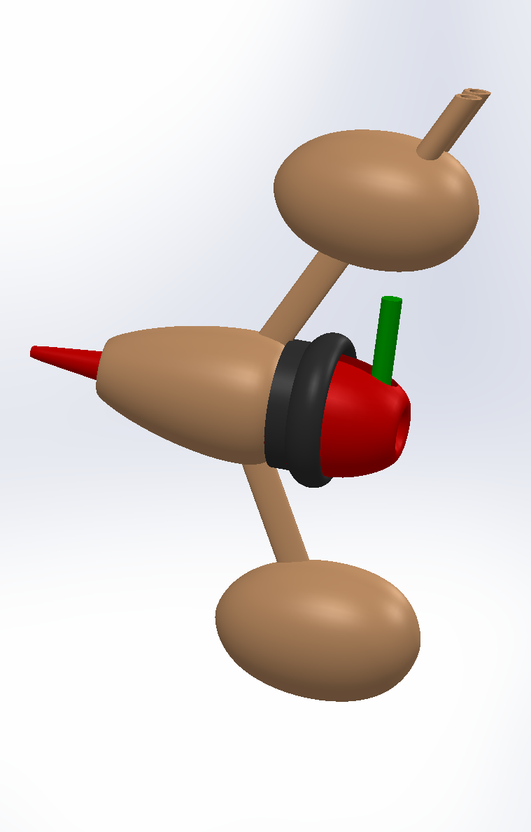
Version 2. Now the rotating assembly sits around and behind the inner part so that there is more space inside the inner part for a clamping mechanism. Also there is a lever that the ground station could engage that engages the clamp. Maybe the rotating assembly can engage it as well at the top of the loop.
Version 3. The default state is that strong springs clamp the red part onto the tether. To disengage the clamp, a motor moves the black cylinder forward to engage the lever.
Questions now could be, what does the clamp mechanism look like, and how does the motor move the cylinder.

If we’re dealing with cables? Then lift safety system could be employed?
This example uses wedges. To slowly clamp the tethers.
If It was completely magnetic? then an induction coils could be used to slow it down? This can be automated on motor overspeeding? use some snagging system to power by the loops momentum? To bring thing to a halt? This would be useful on other awes systems where long cables/tethers are involved?
It might be also noting the potential for ware on all components? Especially on the tethers with repeated Engagement of safety system. The pulleys will also be a point of high ware. The only issue I can see if if you have really long tether? stopping in flight the whiplash potential will be quite high? No point have half a tonne dropping on your head?
If I understand what your proposing? the red section is free to rotate? The black ring acts as the engagement mech?
Then something like zoom ball? Would work?

I had one as a kid I be damned if I know where that purple thing went? Our might have rotated? The one we have look an lot like the nerf ball? It usually joined in two parts? So can be assembled preflight?
Ingenious Bombul-Bruticus.stl (201.3 KB)
So I was sat thinking if you had a solid wind body with an opening would it work this is a rough working still a few kinks to figure out? But the idea is to have to loop doo something like a treadmill? If someone was feeling brave enough they could retrofit some on the largest aircraft we have for the task?
The loo would run through the mouth off the solid body? Running over as many rollers as possible? It currently quite a rough stl. But I can improve on that? Mainly a visual for now? The streamer would run through the mouth? Can be as long as required? Even stacked up in a kite train if required? Flying letter boxes?
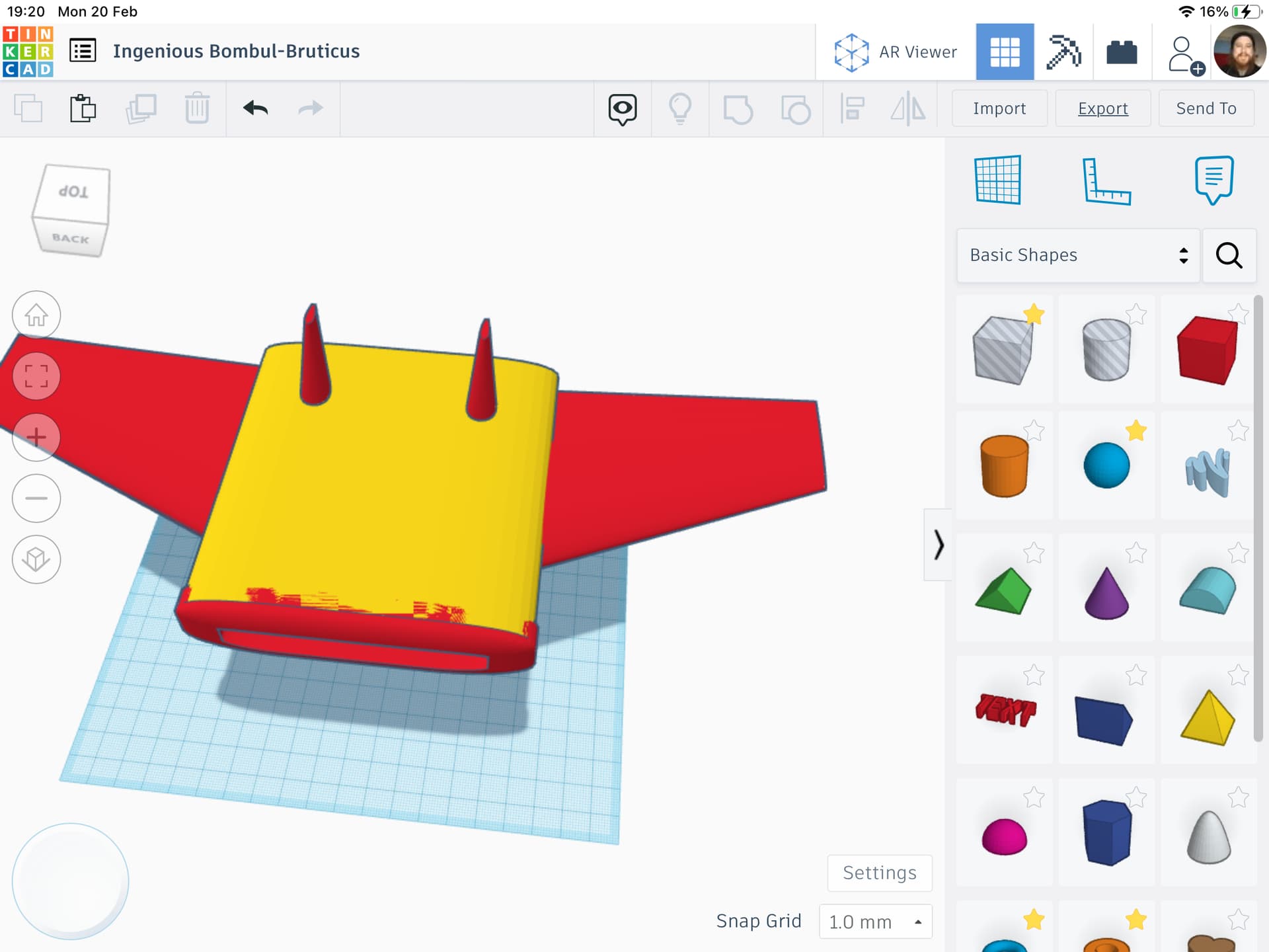
Not quite thunderbird 2 but Getting close?
@PierreB @Rodread @dougselsam @AweEnthusiast @tallakt @Windy_Skies
In theory the size is only limited by material capabilities?
Co flow jets can be employed in numbers of ways? Even as an means to draw a more air in? For instance

Co flow model like this With ion components? Might help?
Would need to be custom fit? But totally doable! With such a design there is ewicon possibilities? Though more weight and more cost!
Just a question of how large you would want one?