Claim: Kites in a MAWES need to be able to: CLAMP onto the tether and LATCH onto the previous kite + a discussion on how to do this + a first mention of stackable kites + a concept for automatic launch of a soft kite train

I haven’t seen this before, so:

(1) I claim that a foundational and prerequisite feature for Multiple-kite Airborne Wind Energy Systems (MAWES), that I haven’t seen mentioned before and I think is innovative, is that each individual kite, or other rigid element, except the topmost ones, need the ability to clamp onto the tether and latch onto the previous kite or the kite cradle on the ground station. This would allow for automatic launch and landing by reeling the tethers in and out.

A similar idea, but now for a concept of a laddermill with the kites flying crosswind, probably by the entire assembly rotating around its longitudinal axis, I claim would need a controllable clamp: More laddermill / spidermill ideas - #54 by Windy_Skies

(2) Another more obvious claim is that another prerequisite for MAWES is stackable kites. From that follows the deletion of vertical tails in favor of, for example, v-tails or no tail, and a new fuselage:wing thickness ratio, which should be as close as reasonable to 1 in order to limit the height of the stacked kites on the kite cradle.

(3) I also claim that there is no viable AWES that would not benefit from being turned into a MAWES. Kite control would be easier, not harder, as perturbations get averaged out, and it would allow you to use smaller, relatively lighter, relatively cheaper, relatively more robust, relatively easier to build, relatively easier to outsource, kites, for equal or greater power production. It also allows you to more easily scale kite area and with that power available per ground station, which I think is a good metric to use. This all gives you quicker research and development and return on investment.

  • If torque transfer is viable, using more and smaller kites would increase tether tension and angular velocity, allowing the shaft to become longer and reach greater heights.
  • Flygen uses rotors on the kites, which take up vertical space and with that make the kites not as easy to stack, so that would require some thought.
  • For soft kite (reeling) systems you could consider using two or more clamps/pod per kite with tether length being controlled by the ground station, or a single smart clamp/pod that controls bridle length.

I don’t remember seeing this before, but I think a potential classification would be single tether vs multiple tethers. Single tether systems seem at first glance to be easiest to control as you eliminate the risk of kites flying into each other, but: with at least 2 tethers you can more easily restrict the flight path radius of the kites, and Tallak chooses 3 tethers in his Pyramid to also be able to counteract gravity. I think the more tethers you use probably the easier it is, as the next kite in a rung sits more directly behind the current kite instead of at an angle behind it, and now perturbations within a rung also get averaged out. You’d choose a higher rotor solidity for traction I think than for electricity production.

I will focus mostly on (1) and how to make that in this topic and I hope you do too.


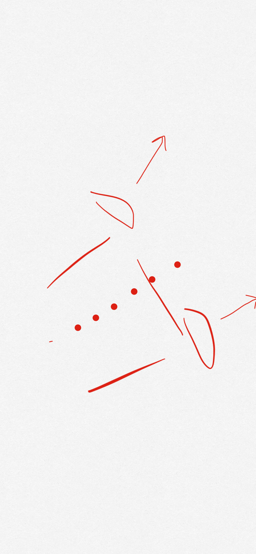
(4) A concept for automatic launch and landing of a soft kite train:

On the end of the stem of each flower (soft kite), there is a pod with (1) a clamp that can be tightened on or released from the lifting line, a (2) pulley to a depowering line, I think, and (3) a latch that can attach and detach the pod to the previous pod.

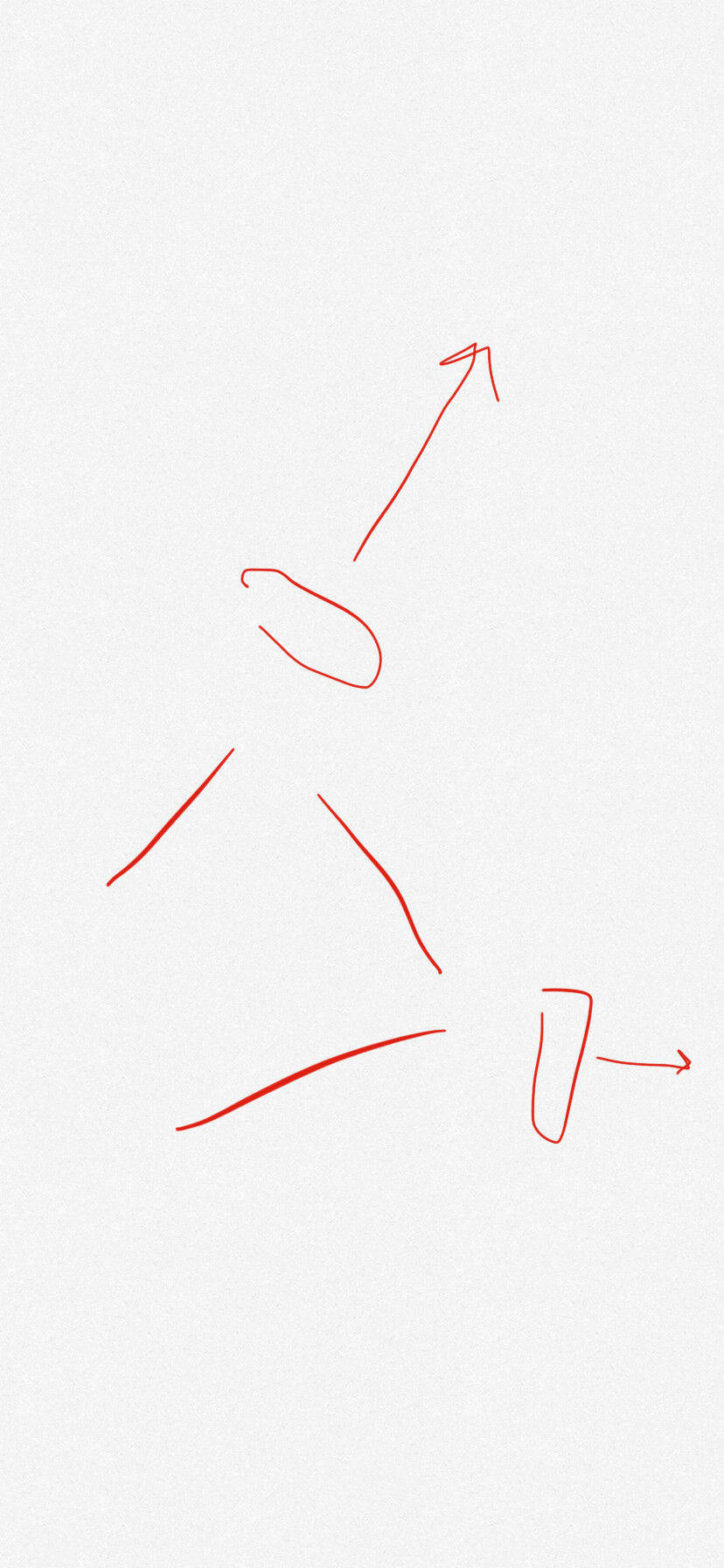
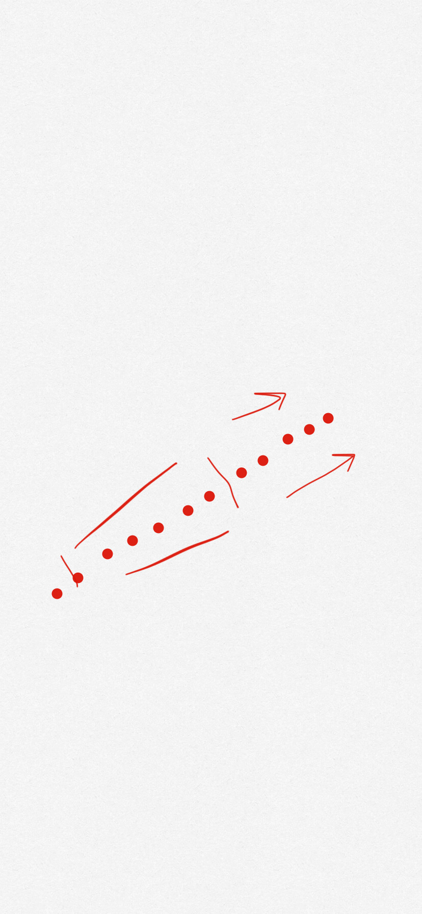
The lifting line is wrapped around a drum at the base of the vase.

To land, potentially depower some of the kites and reel in the lifting line. As the first pod hits the cradle, it releases its clamp on the tether and latches onto the cradle. The next pods latch onto the previous pods.

To launch, let the pilot kite pull on the lifting line and one by one clamp the other pods to the lifting line and release the latches to the previous pods, pulling the kites up.

(5) Last claims: Adding a (train of) lifter kite(s) to any concept except reeling systems, where it seems to be detrimental, would:

  • Allow for quicker and longer duration testing from day one;
  • Allow launching in lower wind speeds;
  • Raise the elevation angle and with that shorten the, expensive, tethers needed to reach the promised more consistent and higher wind speeds at altitude;
  • Raise the elevation angle and raise the kites further from the ground, giving you more elevation angle margin and height margin to react to perturbations;
  • Reduce visual impact;
  • Reduce the length of quickly moving tethers at a height most wildlife would be impacted by them;
  • Reduce the radius a landowner needs to be able to deploy the system;
  • Add a secondary safety mechanism and with that square the safety;
  • Increase the elevation angle and with that also reduce the distance needed between kites or kite rungs;
  • For torque transfer increase tension on the shaft and with that increase its capacity.
2 Likes

If you stack multiple kites on top of each other, without any external support, you’re inevitably going to end up with a wobbly rickety tower. So you need the external support, i.e. a kite cradle, and if you need that it’s then also better to have that kite cradle latch onto the kites instead of the kites latching to each other as you want the extra weight and complexity and potential added fragility and thickness in the element that is not airborne. This would also allow you to for example lock and release the latches for one kite at a time with for example a single motor connected to the say 4 arms of the kite cradle that the kites slide up and down in, if that should be needed.

The kite cradle should prevent any turning of the kites. That still leaves side to side movement. There’s a few different ways you could prevent that. One way could be to add some dihedral or anhedral to the kites, another would be to add registration slots, to either the kite to kite, fuselage to fuselage, or kite to kite cradle mating surfaces. Another way would be to use a wing planform other than rectangular.

1 Like

Sounds like the description of fairground centrifuge ride ground station Windswept and Interesting Ltd - #106 by Rodread

1 Like

I think this post has a lot of interesting ideas proposed. The reason that it is not seeing more discussion is maybe the size of what is proposed, there are many things and to digest it all is “a mouthfull”. But I will try to take a few bites at it…

Regarding (1) the ability to clamp does seem like the straightforward[est] way to deploy a train of kites. So I agree that this is a core feature for many designs, but still not a strict requirement. As a counter example, “The Pyramid” is a three kite MAWES but with all kites on their own tether. So I would rather state “clamping to the tether seems a useful method for MAWES where many kites share a single tether.” Another counterexample seems to be the W&I system which I believe is lifted from the ground. A third counterexample being someAWE which also has only one layer of kites, but clamps the tether spars instead (though I am a bit unsure about the details on this one)

Regarding (2) stackable kites, I think the previous paragraph should display some counterexamples to this claim. Again, stackable kites would be a subset of MAWES, unless the other designs I mentioned are proven to be non-useful. Also with stackable kites you do get a scaling boost, but on the other hand you also get handling issues, maybe cost issues, and maybe some other issues to. So its hard to say one or the other is the strictly best option.

Regarding (3) again I think the wording is too strict. A single kite AWE will inherently have some benefits compared to MAWES such as simplicity and handling wing failures. These must be weighted towards the other benefits that you mention, but I believe there is no rule, just benefits and drawbacks.

In the end, the problem seems to be first to carve out a design based on the principles mentioned above. Then the second problem seems to be implementing these designs.

1 Like

Fair.

I should restrict the claim: I claim a (M)AWES interesting to me needs these things. An AWES is interesting to me when it has the potential to outcompete regular wind. It would have these features:

  • A clear path to >>> 1 MW generation capability – the assumption here is that one 10MW system is going to be cheaper, all things considered, than one hundred 100kW systems.
  • A clear path to do this cost-competitively
  • Working surfaces at or above 300 meter height so you are not restricted to offshore and overly windy locations.

For the Daisy for example, at smaller scales hand launch makes sense, for bigger scales the back bot could make sense, but at the largest scales I claim clamps and latches make most sense.

For the Pyramid, without this, you are restricted to a single rung which would limit you.

I think they are both absolutely necessary research directions, and should be, like they are, researched before adding the extra complexity that this inevitably brings. They might be viable, cost effective solutions in some situations, but the scaling potential that adding clamps and latches brings, and could easily be added to either, should make that win out in the long run in the majority of markets.

An architecture like Daisy is instrumental to finding out things like optimal kite geometry, rung spacing, compression element spacing, optimal elevation angle, number of kites per rung, shaft twist, and so on. The Pyramid is instrumental to developing rotary launch, ground station design, and much more. SomeAWE adds a different perspective on rigid element design and kite control. They are all the simplest and with that the best options to research these things.


Also, what I don’t see mentioned a lot is that I don’t think torque transfer necessarily needs to be work for something like this to be viable, although it would be good if it did work. Instead of torque transfer you could use it for propulsion of a vehicle or a carriage, which would be simpler to do than torque transfer but perhaps less useful, or you could try to make a reeling system, which feels more difficult and prone to wear overall. And, like I say in the top comment, there are the more distant options of a crosswind laddermill or flygen.

2 Likes

Staged release is definitely something which will allow scaling rotary MAWES with less horizontal surface area being used for deployment,
Such as in

Which would also be the hoisted deployment method under a lift network like this

I think more significant for scaling will be the implication of designs for expansion of rotors and designs with concentric multiblade , which could also incorporate rotor expansion too

Concentric rotor example

4 Likes

Yes. I remain unconvinced. It always reminds me of this: https://web.archive.org/web/20190512210559/http://gothamist.com/2012/03/08/the_1960_plan_to_put_a_dome_over_mi.php It looks like a cumbersome solution to a problem that either doesn’t exist or will be solved by the time it could be needed. What problem is it solving?

Multiple concentric tethers for a single soft of rigid kite train, maybe. Multiple radial tethers for a single kite train, also maybe. I’m not seeing the appeal of multiple concentric kites. You’re increasing the radius of the fairground ride to accommodate the extra kites, limiting the torque transfer ability of the inner shafts, adding extra complexity to the ground station, adding turbulence and drag, increasing distance between rungs, adding kite SKUs, for what benefit? You could instead add more kite trains at the perimeter of your fairground ride or add extra rungs. The idea was that you only use the outer 20 per cent of the swept area to get 80 per cent of the power production.

Lengthening the tethers between kites in a rung, which seems easily doable.

Your points
(Which I’m still unconvinced of too, but I’m certain are worth exploring.) were

The dome over…
The reason for it being - Passive Stabilty (done some simulations and Testing on this)
It Reduces control overhead for airborne equipment by limiting the lift kite travel with respect to the set of kites on the net. This I’ll claim but would like to further prove - increases safety.
Also - not sure yet to what extents it will effect reliability.
It provides to avoid clashes but may be susceptible to a wide field collapse caused by a rogue single lifter … Still to be tested fully… The system also requires coordinated line winching across the whole field.

I definitely disagree with this…
t looks like a cumbersome solution to a problem that either doesn’t exist or will be solved by the time it could be needed.

I’ll link to a video of the stabilisation effect here when I’m back ashore.
Have not been able to watch on my current connection…
But I think this is the link

As for saying

The reason for it is to maintain power to weight ratio in scaling and keep increasing
Area swept vs blade characteristic length over ground area.
Still to prove though…
By having connected concentric rotors of short blades on a dished net… We enable a much larger rotor but keep it light. Can also improve the induction by having higher numbers of blades on outer layers

Not seeing why this in your opinion limits the torque transmission of the inner (original diameter rotor) kites… Other than in the drawing the torque lines are maintained at an outer (more drag) sweep and not coned inward to a skinny TRPT

I don’t like the thought of this launchings a soft kite arrangement. hmmm maybe inflated rigid.
Yep the Ground Station is more complex than for a single rotor (no concentric design)
It’s on the ground - we can handle complexity at ground level - ace.

What’s an SKU?

This is the video which shows the extraordinary difference in stability which the top net brings.

It starts out without a top net - - chaos - the kites are going everywhere
Then it re-runs with a topnet - - order - the kites are stable (this is the exact same range of random force vector acting as the lift kite resultant on the top end of the tether where the lift kites are)
and again without…

It shows a 5x deviation difference from original setpoint.

So even though you may loose control of your lift kite - With a top net It’s not going to drift into the path of neighbour kites

I should probably re record it in a higher fidelity and explaining the algorithm more

3 Likes

SKU: stock keeping unit

A partial response, only to lift networks.

I stand corrected, there does seem to be a problem of lifter kite stability. Your video seems to exaggerate the problem. The wind is not as chaotic at some altitude and during higher wind speeds, the kite turbines should add some stability and tether tension also - the higher the rotation speed the higher the stability against sudden wind changes - , the tethers should be under higher tension, the lifter kite trains should be more stable, and wind direction changes should effect most turbines mostly equally.

I’ll assume the problem exists and in this topic I’ll treat a lifter network as a potential solution. Other solutions at the scale and for the architectures I am interested in are probably better, like spacing the ground stations further apart, staggered launch of the turbines, active control of the kites in the turbines, replacing passive lifter kites with active lifter kites, a mostly 1D network, or kite train, of lifter kites for each turbine, and contra-rotating each turbine compared to the ones next to it.

Here a view from above of your kite network: Network of Kite Turbine networks - YouTube, which I’ll assume is typical for your thinking. The network is made up of hexagons, the turbines are arranged in a circle, and the winches are some further distance from the ground stations around the outside. I like none of those things. Let’s think about an arrangement that I think could be better, to make the best possible case for lifter networks.

You want the kite turbines to instead make the, now round, tiles on the surface of a Truncated icosahedron - Wikipedia or geodesic dome or the most efficient Tessellation - Wikipedia to cover the 2D ground. You do that by, instead of in the 3D case starting with an icosahedron and attaching your lifter kites to the vertices, attaching your lifter kites, and the turbines under them, to a tether network made from triangles. If needed you could add some extra ground stations, with or without turbines, around the outside to help expand the network.

What is optimal spacing for kite turbines to reduce wake interactions? Let’s assume 10 times diameter. Let’s also assume kite turbine diameter of 10 times 4 meter wingspan of 40 meters, so 400 meters between ground stations. For each lifter kite that adds 6 x 1/2 x 400 = 1200 meters of tether to lift for this network. Let’s assume lifter height of 500 meters, a distance of 400 meters between ground stations, an elevation angle of 40 degrees. Then each turbine and lifter kite, without the lifter network, has a cone of some 20 degrees it can move in before hitting the next turbine moving within its own cone, for 300 meters between ground stations the cone is some 13 degrees, and for 200 meters some 7 degrees. With the kite network we mostly need to look at the cones the lifter kites make above the network, which can be large for short lifter tether lengths. So a good argument for lifter networks would be the ability to place ground stations closer together, ignoring wake interactions.

You’ve drawn a 2D lifter network. A 1D network, a single tether, perhaps in a circle if you like to place your turbines in a circle like you’ve done in the video, would be easier. A 0D network easier still.

Since we’re in this topic, we’ll assume the lifter kite trains launch using something like the launching method I described in the first comment and the kite network never touches the ground.

Is that the benefit, the potential of placing ground stations closer together? What other benefits and drawbacks does it have?

1 Like

Flat open terrain or floating deployment will definitely suit basic geometry anchoring and ground station layouts.

Real world farm fields tend to be more limiting. They’re often rectangular at the edges. (often used a fencepost as a kite anchor)
If you want to play with changing boundary anchor shapes for inflated net systems
Here’s a good beginning tutorial How to: Interact with Mouse in Grasshopper, Rhino - YouTube
You can use that on my earlier definitions too.

The other real world limit is sloping ground.
It’s easy to plonk a standard wind turbine onto flat ground. There’s not a lot of that here.
We want our top net to be wide and tensioned for stability
Which implies either compound convex curvature of the top surface of a lifting kite network.
Or
Deployment via suspension across a valley

The goal is to have taut tethers. Let’s say you want to start with the simplest kite network, a single horizontal taut tether, the more tension it is under the better, some distance from the ground and suspended from a number of kite trains, probably only on either end, no turbines attached to it yet. What do you think that would look like? What elements would it have? How would it launch?

Or… What about using clamps and latches to also have multiple of these horizontal tethers above one another, making a kite network in the plane of the elevation angle instead of horizontal.

Kind of off topic here:

A copy of a fully tensile Daisy, or the Pyramid with multiple layers of kites, but now with only a triangular bridle between the topmost rung of kites and at the top of the shaft, so no lines connecting individual kites / blades in other rungs. With that I imagine the overall shape of it will become like a twisted, kite populated, ovoid or hot air balloon shaped profile above a twisted stem. The more tension it is under the narrower the ovoid would become.

You’re still restricting the radius of the flight path, but less so, so I imagine it still helps with decreasing the amplitude of the sine wave the speed of the kites make as they are making the circle. And now you’ve got somewhat simpler and lighter kites that don’t need an extra motor to extend and retract the triangular bridle and you have less lines that can become slack and add drag.

If you don’t use lifter kites, maybe also only the topmost (several) rung(s) of kites needs to be “smart” to be able to steer the system, with the rest perhaps not or only occasionally needing to adjust their control surfaces.

Maybe now the kites above and below the current kite help with gravity, if the tether is twisted, similar to the triangular bridle would? I can’t really visualize this yet. Would individual tethers look like bulgy helixes, or would they be bulgy, twisted, straight lines?

What do you think @Rodread, @tallakt?

Somewhat related: The Pyramid, marginally related: Swarm Robotics.

1 Like

Sound cool
The number of successive layers of rotors (Rungs in your description) without the inter blade tie connection should probably be limited dependant on the geometry ratios and aero stuff.
Otherwise you’ll likely get complications of slow down, and/or catch-up effects

1 Like

Here is not a claim, but an observation and an idea:

If all you are doing is flying in circles, and even more so if you are connected to the front and back of other kites, you don’t really I think perhaps need to vary the bank angle. Perhaps you can manage to change the direction of your tether / soft shaft just by using your rudder or ailerons.

If that is true, you can use a bridle. And if you can use a bridle, and you can clamp your kites to the tether, you can have one or two tethers going from the ground station to your bottom-most kite, where it splits into however many tethers you like, to act as a bridle. So there would be one or two tethers going from the ground station to the bottom-most kite, after which they split up and you have more tethers between the kites.

The point of this is that you then could have a long shaft with fewer tethers and with that less drag, but you also kind of solve the scaling issue with the help of the bridling. And perhaps control becomes easier.

An important variable here is how much distance you put between the rungs of your system, too much and you are increasing tether drag too much again, probably, and you could have added more kites along the tethers. Too little and you’re flying in the wake of the lower kites, probably.

Another important variable is the, now fixed, bank angle at the flying radius you choose. The higher the bank angle, the more control authority you would have I think from the ailerons, which I think is important, and the more shaft expansion, which I guess is important if you want to do torque transfer. Also since the kites now make parallelograms with the tethers, the bank angle of the bottom-most kite fixes the bank angle of the other kites (assuming no shaft twist, maybe), but not their flying radius, unless you get fancy.

I’m not certain of this, but I think if you set the knot for the bridle at some position under the kite, the element on the cradle or arm that the bridle emerges from has to match that, which limits your bridle height. You’d have to make your bottom-most kite stronger to account for that.

What do you think? What are drawbacks?

What do you think about the control? I’m thinking control should be much easier now that the kites seem to be fully constrained?

If you’re not flying in circles and want to fly figures-of-eight or you do want to vary the bank angle or you want to use two tethers to control the kite from the ground, I don’t know, instead of tying a knot at the bridle you could use pulleys maybe, or beads with openings for the bridle tethers. I think they’d probably have to be small though as they would need to be wrapped around the drum and go through other elements before they reach the kite cradle.

2 Likes

You are right, if you can use a bridle you get

  • support of the wing
  • much easier control
  • your ability to control outwards force for tight bridles is limited
  • handling the kite when reeling in the tether is somewhat more complicated
  • if you want a release mechanism or a tether tension sensor, that is more complicated

The reason I mentioned if, is that unless you have a lifter kite, you need variable roll angle throughout the loop [bank angle] if you want to produce a net lift force to control the shaft elevation angle. You could use a vertically aligned wind to provide such lift, but for me a single wing seems simpler to deal with probably also better aero efficiency.

Leading me to think variable roll [bank] angle is the way to go?

We would also have the option of just having the lower force be bigger than the upper force [around the loop] creating a elevate up moment on the force. But this has the problem of having to reduce the lift of the wing at the top of the loop, which in turn would lead to presumably less power output for the same device

2 Likes

@Windy_Skies ,

There might be some interesting things. Could you draw up some diagrams of the different options and architectures you are planning, with captions for items such as clamps, latches, bridles, tethers.

As a start what would be a sketch of an architecture allowing to

Thanks.

1 Like

You pointed this out before. Can you expand on this?

My thinking was, if you have a fixed roll angle of 20 degrees, you could use flaps or flaperons (not ailerons I guess like I incorrectly say above) to increase the lift portion perpendicular to the shaft while the kite was at the top of the loop. So if the kite produces a total lift of 100, 20 would act perpendicular to the shaft, and you could increase that to something like 22 to steer the shaft in the direction you want. But this kind of contradicts it seems with your last paragraph, where you say that would result in the shaft being steered down instead by the extra lift in line with the shaft?

Thinking about that, a wing portion (or airfoil that you rotate) that is (close to) parallel to the shaft like you say seems better maybe, as then only that part of the wing, or only that airfoil, produces extra drag while you are trying to steer the shaft.

I’m not sure I understand you correctly, but if we assume you set some fixed roll angle at a flying radius of r and a shaft length l, you can make sure that while the shaft is still extending, the triangle that the kite makes with the kite cradle and the shaft stays the same shape as the eventual triangle, so you keep a constant roll angle. You have lost the option to dynamically make the triangular bridle much smaller than what you designed for however, as then the roll angle becomes too small, if you chose a roll angle and not some vertical airfoil.

I hoped with the bridle idea, not all kites need control surfaces, only the ones that you use to steer the shaft? Or do you think you need to actively change the AoA of the kites in the Pyramid for example when you transition from rotary launch to letting the wind take over? Or when switching between any two flight modes?

Edit: perpendicular to parallel…

1 Like

Not now, maybe in due time, or maybe not. The basic idea is that you have a system like the Pyramid, but instead of only a single tether attachment point at the bottom of the glider, you have one at the front of the fuselage to connect to the kite in front, one at the back of the fuselage to connect to the kite in the back, and several bridle attachment points. That also looks very similar to Rod’s system if you replaced his blades with gliders.

Could you do it like that, would you need extra control surfaces, and what would controlling this look like?

1 Like

So disregarding gravity and the fact that wind is blowing along the ground vs elevation angle of the shaft, and aligning the wings with the plane of rotation, the lift vector would point along the shaft centerline.

To compensate for those things above, you need on average to point the lift force vectors somewhat towards the sky. This means some kind of cyclic change of attitude of the wings.

The easiest way to do this would be to roll the kites in a cyclic manner.

Im not sure if that explains what I am thinking about.

Cyclic change of roll

Fixed roll, cyclic change of force [angle of attack]

Wing at zero roll in P-Plane (plane of rotation). Cyclic force adjustment [AoA] but shaft elevation angle is controlled by overall moment application

2 Likes