Thanks. Okay, I understand that. But using a bridle and then say an airfoil orientated parallel to the shaft has some potential major benefits, so I potentially like that better. The question I would have is would it actually be that simple; just have a motor that cyclically rotates that one airfoil while it is going around the shaft for the controllable kites, and have no moving parts on the other kites, except for their clamps and maybe elevators or something. Is there some dumb mistake in my thinking or am I not understanding some major disadvantage?
The benefits would be: much lighter (but potentially more fragile) wings, if we assume you want larger wings for their higher Reynolds number; only have moving parts on the controllable kites, so less moving parts overall so less to go wrong; if things do go wrong, the kites are better constrained; and much easier control.
And then if you have lighter wings, you have to counteract gravity less, which would then hopefully give you less of an added drag penalty for the steering.
And thanks for the sketches. Previously or still my thinking was to perhaps do a variation of the second one, where you’d use either flaps on the wings or elevators on the tail to change the shape of the wing or the angle of attack. Which you would choose would depend on the tension in the triangular bridle and the moment arm about the center of gravity you chose for the triangular bridle attachment points, and then the drag losses vs complexity of either. More: The Pyramid - #60 by Windy_Skies
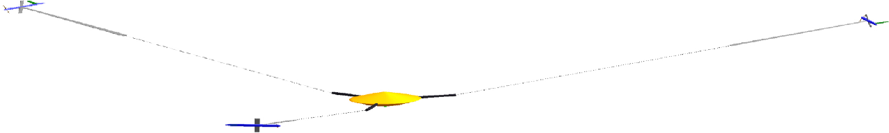
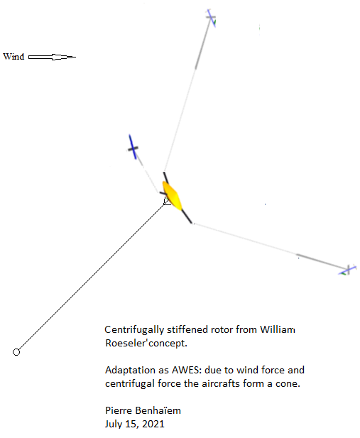
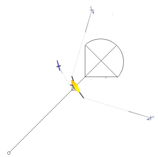
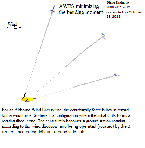
In the CSR, such as described on the following documents and the illustrations, the wing is in the extension of the tether. Here for this post, the “centrifugal force” aspect is not considered first.
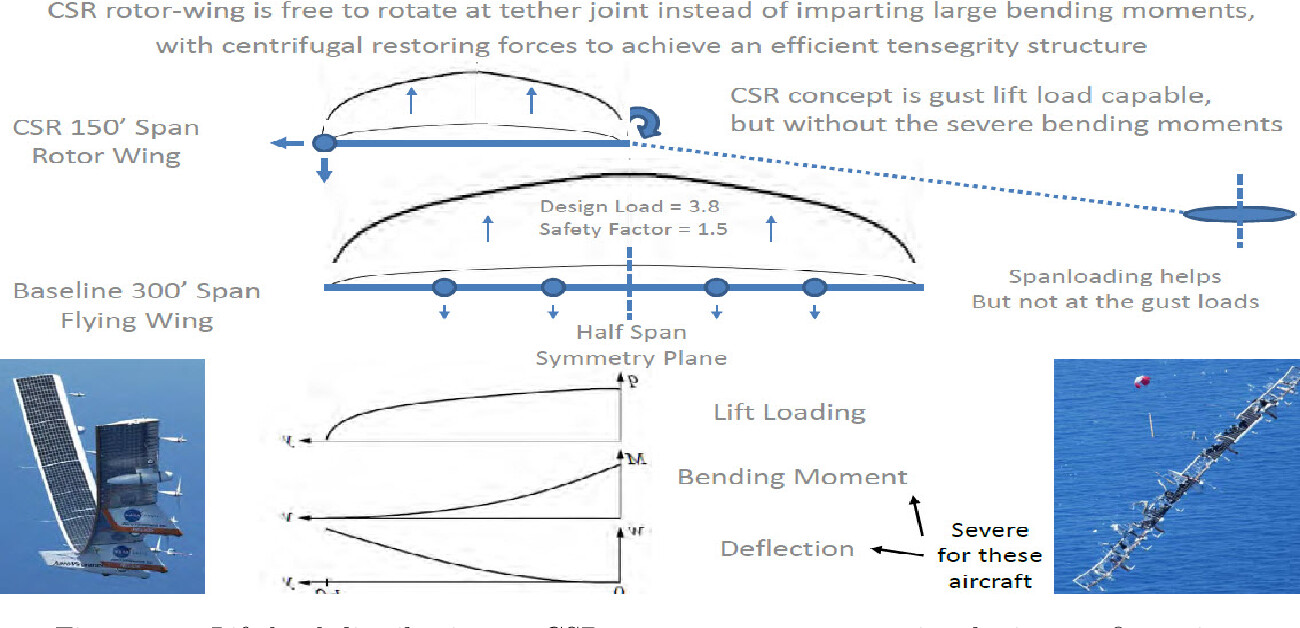
Page 19 (see also page 16):
1.7.1 Airborne Wind Energy […]
Because the tether connects the aircraft to the ground, the tether orientation to the aircraft is 90 degrees to each other so that the tether imparts a significant bending load on the wing. If the CSR concept were used in place of the conventional Makani aircraft concept, the ground tether would connect to the stationary CSR center hub and not experience a velocity or drag. The resulting drag of the system would be much less, and permit smaller land use as decreased tether angles to the horizon are accomplished. In addition, the CSR approach would maintain the ability to keep the rotating tether between the hub and rotor-wings along the span path to achieve a lighter weight solution.
On a very basic level the idea is simple, and yes it would fly.
I am reading the Elon Musk book at the moment and will try to make a comparison. Saying this AWE is simple is like saying sending a rocket to Mars is as simple as having a huge fuel tank and thrusters. If the energy adds up, you will arrive at Mars.
For sure having things adding up is a very good starting point. I think many fail even before that. But if you actually want to build something useful that of course is a whole other story.
For the rotating AWE I would argue that dealing with oscillations is a major problem. If we just stick the wing to the tether, it is going to deflect and bend, then cause oscillations. So the designer needs to figure out if that can be acceptable.
Having a single wing will always be the thing that has the least drag. So for me I try to stick to whats more efficient, if possible. Look at windmills in general; they seem aerodynamically very efficient. Why bet on a non-efficient AWE design?
As for any design with variable pull force, that structure will deform cyclically. This was very deliberate when I came up with «The Pyramid» to keep the flying speed and tension in each tether constant so that I would never have to deal with that. I am thinking start as simple as you can, because multi kite AWE is already way too complex.
And so it goes. We can only discuss quite basic things in this forum due to time and bandwidth constraints. Any effort to build a real system would require thousands of hours of work and careful thought put into so many facets of the design.
With «The Pyramid» I wanted to present a concept that would serve as a good starting point for something real. There is much more thought put into that design than meets the eye. So many options have already been discarded on the way. I think it would be unlikely for anyone else to arrive at the same design and have my exact preferences. If you could not yourself deduce the design from scratch you would most likely not be well situated to complete the design in a good way. The way it stands, I hope though it may serve as an inspiration.
Because the bending moment on the blades of a windmill, and the most energy is generated at the tips of the blades. Your idea, among others, solves that, hopefully. This expands on that, subdividing the bending moment even further, and adding additional rotors behind the first one. It is one more possible answer to how to make mostly tensile wind turbine blades.
Because it potentially allows you an incremental R&D progress with a gentler learning curve. You start out with something that looks a bit like Rod’s system, which we know seems to kind of work, and go from there. And if you get bored with that for a while or decide to pivot or decide to test things in parallel, which is bound to happen anyway, the ground station you designed should mostly still be relevant.
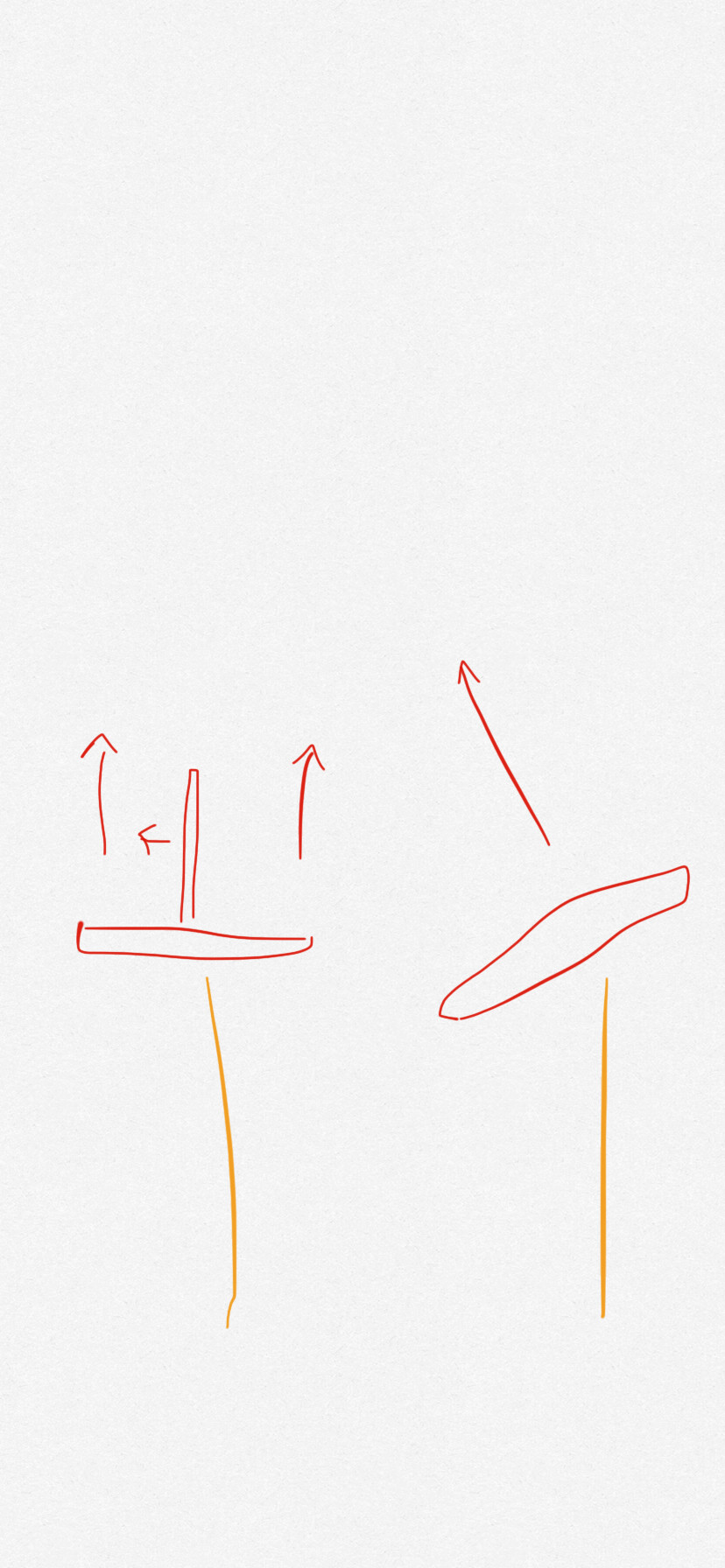
My thinking was that your wing on the right would have to be probably several times heavier than the one on the left, because the one on the left would have bridling, so the drag cost of counteracting gravity would also be several times higher. We also pointed out several other big costs of not using bridling.
The drawback of bridling is that now your roll rate is constant, so you either have to use a [1] second tower to tension the shaft, use [2] lifter kites, [3] vary the pitch cyclically with a horizontal tail, cyclically use [4] flaps, cyclically rotate a [5] vertical airfoil or vertical control surface on the wing, [6] have a vertical rudder, or [7] rotate the wing.
I don’t know which is best. Starting out using [1] or [2] is probably a given. I think [4] is probably bad aerodynamically, [3] would be good, but requires rotary launch and constant control, and still has the additional tail airfoil. As long as the triangular bridle is under tension, [5] seems simple, and for when it isn’t you can add [3] and [6]. I don’t know about [6], but that still requires horizontal and vertical tail surfaces.
All the options that vary the lift in line with the shaft, also do that extra work (most of the work if the roll angle is less than 45 degrees), so you’d have to add a modifier to your drag calculations. Instead of only your vertical surfaces adding drag cyclically, all of them are, with most of it seemingly wasted.
I would be careful to make assumptions. Fibers dont come in 90 degree bends. Its easier to make a single long wing than a 90 degree interconnection.
Bridling is always an option, though I have so far steered away from bridles. Bridles have issues in particular with handling. Also I believe bridles may have some very large implications on durability.
That being said a structure with anti-bridles [vertical beams to support bridles] and bridles is interesting to me.
I think also that probably the easiest way to do this would be to integrate beads into the tether that these clamps then clamp onto.
Given this, you could then also connect these beads to a conductive cable inside the tether. And then connect the conductive cable to a slip ring between drum and shaft, and you’d add another slip ring between shaft and nacelle. You’d only send (max) power through the cable once the tether was completely unwound from the drum to avoid the cable heating up too much.
One imagines it might be a good idea anyway to add this even if you don’t go for flygen to power things that need power on the kites.
If you do go for a flygen system, and since now you would have lots of generators in the air, you could connect them together in series and with that increase the voltage and with that make the cable much lighter, I think that’s how that works: Lightweight conductive tethers, fairings around tethers since the cable is airborne and not in danger of being touched, I think it also makes sense if the need for cable insulation decreases.
And since with flygen, or yoyo systems, if talking about a system like the Pyramid, you don’t need torque transfer after the launch, you could cinch together the tethers from the different kite trains to reduce tether drag, or fold the arms up, like a flower closing up.
I think none of these options rule out using a lifter kite train or things like that, at least for initial development so your kites won’t crash as much then.
I also think flygen would probably be easiest to develop, but torque transfer perhaps more viable, if it works.
Splicing or makibg knots on UHMWPE rope is very hard. What I see in kites is loops terminating tethers sewn with a surrounding webbing at least 20x the tether diameter.
I think its hard to see a system using a metal part inside the tether being as strong as the tether itself.
A soft shackle and diamond knot is a good place to start.
Because its all the same material a lot of the wear concerns I have would me mitigated.
The diamond knot could be put on an appendix from the main tether that an equipment could latch on to.
The more straightforward way would be to terminate the main tether in the middle with loops and then add a metal shackle to attach equipment to.
Anyways, I think at least this shows the details concerning tether is not trivial. Best if you can avoid anything other than the structure reel-tether-loop
I suspect the claim that a MAWES needs connectors isn’t right.
I can see the deployment and recovery advantages at scale (especially scaled numbers of kites) of being able to attach detach
but
I flew some simple Daisy efforts which were tied right through.
And simple works.
Also
You could run a network configuration with integrated winching e.g.
Use a top lift (or train) to initiate lifting of a network of kites which self furl in the following configuration…
A stack of concentric rings of kites in network domes, only unfurl the kites at 25deg downwind by pulling their tether. The kites have a rigid beam element at the concentric line which can furl the kite to minimise its profile to that of a thick line. The upwind (slack tether) kites are sprung or powered to wrap around the concentric ring lines to minimise their profiles and pull their neighbouring kites close in.
The upwind dome radial lines tension from the top lifters might be enough to hold the furled sets while the downwind net of lifters is worked for crosswind tension utility.
Sounds like a lot of faff to operate though
Likely to be too complex and tangle prone.
The complexity could be mitigated to some extent by manipulating the feet around the base station…
As was proposed donkeys years ago in the Mothra network type kites of yore
But this foot handling arrangement likely also requires a lot of material / hard work…
And again… this can be done without requiring attachable modular kite elements
My need in need to be able to is doing some work. Before I wrote this about that:
Interesting to me you could also read as able to replace or be cost-competitive to cheaper by an order of magnitude compared to conventional onshore wind, able to survive storms, have durable parts, and so on. It needs to be economical and practical, not just physically possible to construct and work that one time after years of development. Trains, not (human-powered) helicopters.
Can you place it somewhere in the Leeds or Vancouver region, as that is where the energy needs are, is it cheaper than other energy sources, and can you leave it unattended?
Both of your examples don’t seem to qualify, and with that I think aren’t good counterexamples for my narrower interest. The Daisy efforts would be a good counter example for the original claim, your network dome wouldn’t be as of now, as we don’t know if it can exist. For my narrower interest, your simple Daisy efforts would have a too low rotor height, be too small scale to be economical for grid energy, and so on. I don’t really understand your other description, if it looks kind of like a multi-rotor, soft kite, Daisy but now networked together, the soft kites would make it not efficient enough per land area to compete with conventional wind I think, among other problems.
…This is partly me thinking out loud about commercial viability and not really a reply anymore to your comment.
My philosophy is to use one large lifter kite, like a circus tent, which remains open at all times. No furling, folding or clamping. It is supported by a lifting frame, or alternately lifted by drones. The tether is extended at all times. No wind/unwind reels. This is the easiest system to operate with autonomous control.
This is kind of turning into a random ideas topic.
Here is another one: If you have a rotary AWES where you are using ground control by varying tether length, a good way to do this I think is by adding (multiple, concentric) cylindrical cams that can rotate (to be able to control the direction) and that can move in and out (to vary the amplitude of control line variations).
The cams would extend from the nacelle and go around the shaft. They would only come in contact with the control lines. They would look like concentric tubes, with the end that comes into contact with the control line being shaped.
Maybe you’d use a number of these cams, concentric around each other, to even out the wave of control line length you would be producing. If you imagine the graph the control line length would make if you only extended the cam out partway so that it didn’t impact the control line through part of the rotation, it would be a flat line during that part of the rotation instead of following the profile of the cam.
Another reason to add more cams might be to add more control inputs. One could maintain elevation angle and heading while others could do different things.
IIRC @someAWE_cb uses mostly the same basic principle, and I am sure the same basic principle is used in many other applications.
The benefit would be that you don’t have (strong) motors or other actuators constantly varying the tether length around the rotation, one for each tether. There are probably many drawbacks as well, one would be that you can probably only design a cam, and determine if it’s a viable solution, after you’ve tested your control inputs in some other way.
A different question might be if you can do ground control at all if you are doing torque transfer. I think a relevant question for that is the phase difference between the top and bottom rotor. The smaller the better I think so that your control input results in most of the kites in a train being pointed in mostly the same direction and your control input and added drag from that not being mostly wasted.
The control lines would be the followers in this case. The control lines come from the drum(s) and make a straight line through several pulleys or rings. The ends of the tubular cylindrical cams would push the control line up between these pulleys.
To reduce wear from the cams on the control line, between the rings, you could route the control line through beads that include a bearing and a grooved pulley to let these beads, instead of the control line itself, ride the tubular cam.
It is an attempt to simulate having several concentric swashplates, or the same kind of effect that they would have, that can act on control lines.
I don’t know how you would make it though. At first one or more linear actuators mounted on the shaft for each control line so you can program control line length at each point during the rotation, and during different flight stages and weather conditions, seems better. Maybe later add a single non-rotating tubular cam that only was for maintaining elevation angle. Maybe later add one or more additional cams, perhaps. Or perhaps only the elevation angle adjustment needs to be always on, so only that would really benefit from the cam, or perhaps actual swashplate.
Tallak pointed out some ways to control a rotary AWES further down in this comment:
My cam idea above adds another idea perhaps that doesn’t need a change in wing attitude. You can make it so that the cam reels in the tether slightly at the top of the loop, and lets it out slightly at the bottom of the loop. If then the wing has some roll angle, if the assumed slight differences in experienced wind speeds between the top and bottom of the loop then also result in the kite flying slightly faster at the top of the loop than at the bottom, enough to overcome the weight of the system and then some, the shaft should be steered up.
If you only have a single heavy wing, I don’t think this would work, as then the kite would be moving fastest at the bottom of the loop, I think it was, and this wouldn’t have enough of an effect. This could work I think if the kite originally had close to the same speed along the circle, so if it were lighter and connected to other kites to the front and back. You could perhaps stack several cams so that you could have a useful variance in tether length. And as you have several tethers, the cam could let out one tether while taking up another, lowering the power required.
What do you think?
Edit: Oh right, this shouldn’t work if the kites are connected, every kite in a rotor would move at the same speed. But would it have some benefit?