A bit of a different idea, with the clamp you can either just clamp the tether between some flat or curved surfaces, or you could use wheels that you could brake (which could perhaps be useful for other AWES where you might want to use a similar mechanism but instead use wheels where you brake the wheels if you want more control over its speed), but if you are going to use wheels you might as well keep the loop static and put a generator in the pod, and have the generator in it generate energy while going downwind, release the wheels while you glide upwind, and release the stored energy at the ground station. Or some different combination where you take advantage of the potential energy of the kite and pod.
Or can you? How is this going to interact with the loop attachment points on the ground station?
One thing I don’t understand is the strength of the rope for the loop that you then need. Is it going to be the same or not? Is it going to wear more or not?
Imagine what would happen if you made that and attached a string to the mouth. Would it make a good kite then? Where should you attach the string? You have to start from a good kite design. This topic is not really about kite design.
Multi point bridal can attach to the aerofoils? leaving room for the streamer to run through the mouth? It can with not too much modifications? run smoothly underneath the lower part of the wing body? Then back through the mouth in a continuous loop? I’m aware of ovoid wings and rings wings
They do exist? Makani was just one example of a solid body kite.
For example?
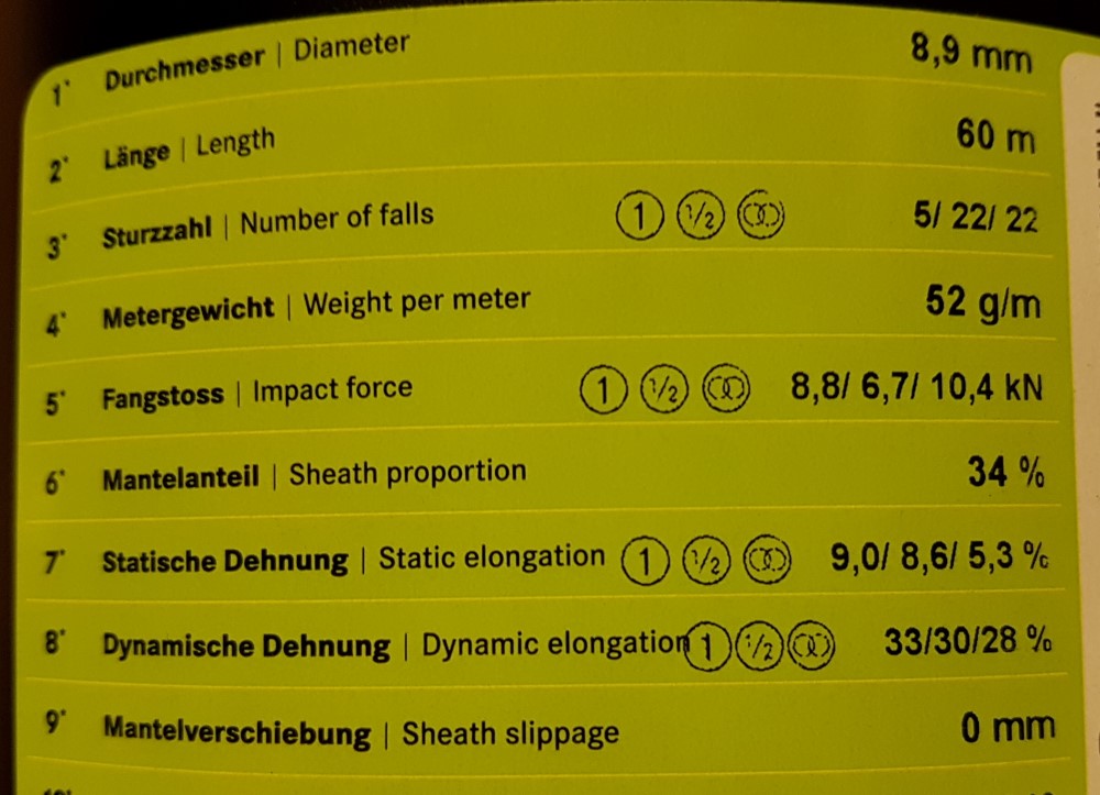
I might be able to give you some ideas on braking strength of various grades of paracord?
Usually the more strands it has the more strength? Climbing rope is usually rated in multiple of bodyweight? Because it got to get a man and his gear up hill?
I thought the topic was to see if there were things that could be done? to help ladder mill and spider mills along? That might even mean exploring design options?
In variants 2&3’s case?
2, can be a triangular bridal connecting it to the ground station?
3. Can have the cables running up to the multipoint bridal ?
Any oh? just trying to provide as many visual cues as possible to put the point across?
You don’t seem to understand how laddermills work or how wind energy works or what I am talking about. Instead of trying to learn more, despite me asking you repeatedly, you are here doing this. You have to understand a thing before you can improve on a thing.
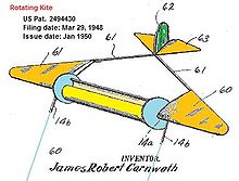
The picture you show here is essentially an airplane, with you attaching a string to the tip of the nose of that airplane. Now go try to fly that airplane as a kite without starting the motor. It will stay on the ground. Now put 10 of those in a row, nose to tail, and they will still stay on the ground.
If you want something heavy like an airplane to fly like a kite, it has to fly in circles or in a figure eight pattern. It has to fly very quickly to generate enough lift to lift itself off the ground and pull on the tether to turn the generator. The lift goes up at the square of the speed, so if the airplane goes 7 times as fast, it generates 49 times as much lift.
When you want to fly an airplane like a kite, you attach the tether to the center of lift of the airplane, I think, not the nose.
My pod above is an attempt to connect this quickly flying airplane or kite to the loop of the laddermill (spidermill now).
My thinking was if the aspect ratio was right you wouldn’t need to fly in circles? The bridle only need to be rigged in a forward direction much like you you see in surf kites for it work? Bridal attaches to the both wings. Therefore there no need for to attach to the nose. just a few point on the leading edges.
What else would you like me to say? I did say I was a roughing out of a idea I had?
I could see how you would attach. Why I mentioned .
Not trying to irritate you. I was being speculative on potential shapes.
The bridal can attach to the leading edge?
It may require a launch system? Depending on size and scale? It would need much pitch control 5% pitch would enough to generate lift. I’m thinking catapults?
The airbus a380 is a good example of lift ratios. That where my thinking was?
I’m not doing this to wind people up? Sorry if I got you goat? Wasn’t what I was aiming at? I was only suggesting on way to loop could warp around?
Hi everyone, just thought I’d inject a bit about the laddermill concept as it related to the SuperTurbine™ concept. They are really two versi0ons of the same concept. Laddermill could be said to approach a Darrieus version of a SuperTurbine™. Alternatively we could say laddermill started out as a “cross-axis” (broader category of “vertical-axis”) machine, but as it matured in my mind, way back in the 1970’s, it morphed itself into more of an aligned-axis (broader category containing what we normally call “horizontal-axis”) machine. In other words, the idea morphed toward what is known to work better, based on my growing exposure to more knowledge of wind energy as it really works. So what I’m saying is the two concepts: (Laddermill and SuperTurbine™) could be said to represent alternative aspects of the same basic configuration, which is a ground-gen-based, downwind-extending, upward-slanting, lift-based, continuous-operation, wind energy machine with airfoils completing a repeated closed-loop circuit, using as much lift, as opposed to drag, as possible . I would say these are the two simplest and most basic steady-state airborne wind energy concepts. To me, they invent themselves, I’m just the channel through which they arrived. And by the way I think there has been a very limited version of lederhosen - er um I mean “laddermill” presented at wind energy trade shows. If memory serves, I think they appeared in what I call “the comedy section” of the show where you typically see tabletop models of vertical-axis machines using, say, maglev bearings, powered by forced air from a household fan. In the case of laddermill, I think I remember seeing a version that fits inside a long, flat box, like a foosball table, but with an open back, oriented more upright, with rollers at the top and bottom, kind of like a solar panel, basically a belt of up-and-down rotating vertical blinds. I don’t know, maybe I’m just hallucinating, but I could swear I’ve seen something like that. And by the way, I can see severe problems with that exact version, as in, there were some strong performance-limiting issues with the exact model I’m referring to.
@dougselsam
A quick search online? This came up? Doubt it the one your talking about?
Any chance you have a pic of the foosball version?
Central roller in the Centre?
It would Seem for Comparison sake this would be nothing new?
My Chain of thought is in the 50s? only another 75 years to catch up on? Closing but a long way to go!
Nope! I don’t think you were hallucinating? May end up looking like a roller blind set? But a continuous belt?
At the moment I don’t see a credible way to launch the kites, if you’re not doing rotary launch, as the top of the loop seems to get in the way if you try to launch while circling around the tether. Maybe you could fly a figure of eight pattern instead, but let’s ignore that for now.
So let’s instead think about a rotary launch. Instead of this installation from my quote above that first launches the kites separately, now the kites (pods) sit on, or on the ends of, two arms.
Before the arms start rotating you release the clamps in all the pods, except the topmost one on each arm, so that the topmost kite on each arm can start pulling on the loop.
Now the pods have, beside the clamp, also a motor or spring in them that allows them to extend and retract a (single now) tether to the kite, and a brake that can stop this extending. This brake is engaged in all but the topmost pods. Result is that the topmost pair of kites can start pulling on the loop, and their tethers can start extending. The other pods stay on the arms as the loop just goes through them. There is also a stopper on each arm that keeps the other pods on the arms. When you want to launch a next pair of kites the stopper lets them through.
So, you see the arms start to rotate, the tethers of the topmost pair of kites extend, you release the brake of the drum and the topmost kites start pulling the loop into the air. Repeat for all kites and until the drum is empty and disengaged from the loop. Then you change operation mode where perhaps you could stop the rotation of the arms, or not, and you start the rope drive.
You could decide to keep the kites high in the air by periodically changing the direction of the rope drive, I think, if that doesn’t collapse the top of the loop. Then you could also just use a lifter kite (train), making everything easier.
Or have this lifter kite, but instead only have kites on one side of the loop. The other side of the loop is empty and goes down again, but now through the pods. You’d have a spidermill that from a distance looks like a single tether with kites circling around it, perhaps in opposite directions to limit twist. Maybe you could have the kites go up and down out of sync, like stop-and-go traffic, to limit the size of lifter needed.
Or same principle and just let the empty side be much slacker and longer than the other side so that it doesn’t interfere with the kites. That should be possible I think if you increase the number of wraps around the pulleys or clamp pulleys together to prevent slippage.
All very sensible.
I don’t know it widely used in AWEs
Launch system I had in mind were fairly simple.
Steam catapult is one thing? Magnetic launch the other?
I’m also reminded of the early rescue rocket? For saving people from ship wrecks.
Firstly steam catapult and magnetic launch?
Rocket launch?
The ability to launch the kite to a set altitude then allow the winds to take over? This could be a two stage system?
I agree that flying figures of 8s would be the best use for is as it has the ability to climb to altitude once airborne. If place in a thermal hotspot the task becomes significantly easier? As it could ride the thermal much like paraglide do?
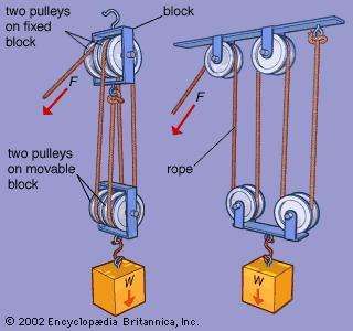
Depending on set up it should be possible to eliminate as much slack in the line? Just depends how far you wish to push pulley design? The pulley themselves can be a self contained generator? With multiple pulleys there should be multiple opportunities to generate Electricity? The pulley would be n a fixed position.
Mooring post are another example of this principal in action the more turn the better the grip? Been a feature of sailing for sometime? There also the possibility of rigging it in such a way that it could enter one side of the rig? Then leave the other? Either by travelling horizontally through the assembly? Or longitudinally?
Depending how many roller it passes? The loop could Zig zag Its way through a circuit? Plausible idea? Requires expert planning and execution.
Lifting regs would apply for for something like this? Though I would be certain exactly where? Safe loading would have to be taken into account? Rated component are a must! Aramid fibres are something to consider? Bullet proofing the design might help it in the long run?
I was thinking on the bigger version of pulling a trick out of the cargo drop book?
Then it might be possible for an auto deploy shoot?
Did notice makani over look a safety shoot? Which cost them dear? Watched the vid with the guy going oh fu………k. As makani made a splash down. It would be good it there was an auto safety shoot? I know certain RC planes have them? Which can the reduced damage and repair?
I don’t know of soils kites that have this? But might be worth a try?
Vertical launch by a first Makani rigid wing prototype, using a catapult:
Horizontal take-off (as for a plane) also by a catapult:
Perhaps the method shown on the first video could be suitable for several rigid kites forming the Laddermill, by launching the top kite. Not easy if even possible.
Assuming no rotary launch and assuming your first kite(s) are lifter kites, you’d use the same kind of pods and clamps with them I think, but maybe have larger low friction pulleys. While wrapping the loop around the drum, you’d leave more slack on the bottom side of the loop so that already after a short while you can launch your other kites and they can start circling around the tether. Your lifter kites pull the loop up, while their pods are clamped to the loop, and one by one the other kites go up and hang from their pods. The kites now would need to be light to be able to go into rotation from being suspended like that.
The lifter kites I think need to support the slack side of the loop, so everything above the top production kite, and also provide some tension for the topmost production kites so that the loop stays in a constrained zigzag shape. The production kites could support their own weight. But a bigger lifter kite make sense so that the production kites don’t need to do that as much, or at all, so you don’t have to program them as much. Counterpoint to that is that then you’d also pull the slack side more taut, unless you wrap the loop around the pulley, and brake it, which is not way you want.
If after a while you don’t like to hand-launch soft lifter kites, perhaps you can make the topmost kite(s) function mostly as lifter kites, perhaps adding propellers to them for launch and fly them in circles above the loop. The loop would perhaps sway with them though, so maybe put them in pairs, one pod below the other. Maybe do that with all kites.
The drawback of them going in opposite directions is that collisions are worse and are more likely to tangle the tethers.
The stop-and-go going up and down the loop in waves, I imagine that to go down the loop again, the kites make a large degree cone, putting them outside of the wind window, while being pulled down by the pod, while going up and pulling on the loop they make a smaller degree cone.
This could be a spidermill variant of the Pyramid. It would need a lifter kite though to keep the slack side of the loop away from the kites (which would rotate around the shaft, which isn’t going to work)*, or the slack side would need to be routed through the pods (now hubs). If you then don’t use a lifter kite and route the slack side through the pods, the topmost rung would act as a lifter kite. As it is more complex and more prone to wear I don’t think this is an improvement on the Pyramid.
* You could perhaps avoid this but I doubt the compromises would be worth it.
Another system to launch Solid kites. It seems even trebuchet might be able to launch it? Even a few old siege weapons might do the trick? There is an option of a ballista style launch? If going really primitive?
Yes… But then I think you’d not route the rope drive through the hub, but have a rope drive for each arm of the ground station, ideally. You need the tethers going from the arms to the kites for launch and landing, if you then don’t use them for anything else they are going to be slack during flight. And you would need a separate system for reeling them in and out. With 3 rope drives you also triple the potential capacity of the system.
I would agree that multiple belt drives would increase output. X number of rope drives? Overall length of rope drives circumference. = the Output potential? Once resistance is factored in? Both the electricity resistance and air resistance.
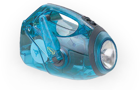
In theory it could just glide back to base? Probably the reeling could be clockwork mechanism? Much like the windup torches?
It should be possible to fully automate the wind in? If it store energy on the assent? Would need a massive crank handle? If you want it to be completely separate?
This kind of launch makes sense but then your next issue is how to bring the kite to takeoff position between flights, ensure no hindrances, and changing wind direction.
Well that where being a history buff helps me? Normally with many types of siege engines? The central launch portion is wide enough and cleared of potential hazards. So less chance of getting snagged up?
Also making sure the the launch ramp/track is complete covered? might help?
Adaptive flight controls might help here? Especially when it comes to changing wind direction? If you have sensor the that can adapt quickly enough? You can have it constantly facing the prevailing wind? That should do the trick? Cross wind landings is one example. I’ve seen many a sketchy take off and landing from my local airport. I remember one Ryanair flight coming in sideways? Praying don’t crash? Some of the most freakiest things I’ve ever seen? Thank you Bournemouth airport for that!
I’m glad you mentioned scaling.
As this would limit the upper limit of size. A sensible size would be easy handle? Also if toying with clockwork the bigger the bird in the sky? The beefier it will need to be? It might be possible to design a gear box and mechanism that does the winding? That can work in forward and reverse? Scrap heap challenge of kite? But doable? Take a tourbillon for example?
So Chime in guys if you think there something I’ve missed? Or you can add to this?
Yes, I think having the mating surfaces be shaped like that is good so that they don’t slip off each other as easily. Another option is to make them like a triangular wedge cone to stop any rotation between them.
For AWE, optimal reel out speed is 1/3 of wind speed, so that means belt velocity, and with that the power transmitted is quite low.
You could try to increase the difference in tension between the slack and tight side by wrapping the rope around the pulley on the ground station a few more times or clamping two rollers together like in the string shooter. The above equation then, I think, if you assume tension in the slack side goes to 0, becomes:
Power = tension \ tight \ side \cdot rope \ drive \ velocity
Let’s assume wind speed is 9 m/s, giving you a rope drive velocity of 1/3 that of 3 m/s, and the kite pulls with a force of 1000 Newtons (100 kg). That gives you a power of 3000 watts.