Physics and selection of a TRPT soft or supported shaft

Hi. I would like to toss out a few things I have been looking at lately, trying to answer; what is an optimum structure of a TRPT [tensile rotary power transfer] shaft.

We have seen some examples of this already

  • Windswept and Interesting’s Daisy [and other] design
  • someAWE
  • Sketches featuring a single shaft segment and a ground rotary track or cartwheel

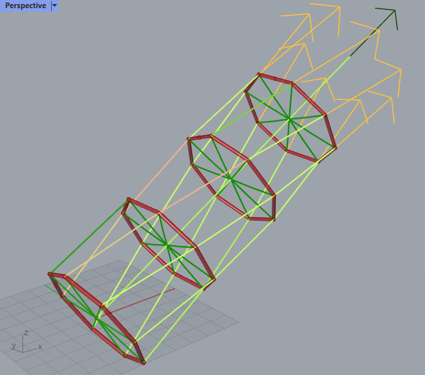
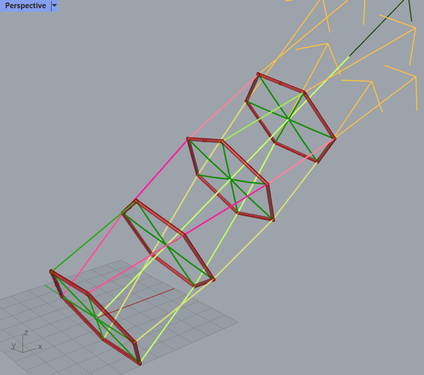
First just some physics. We assume that the shaft is made out a stack of n segments. Each segment is supported at each connection layer by rigid expansion force elements or ultimately the kite lift and centrifugal force. The shaft is dependent on a shaft tension we’ll call T_N in the direction of the shaft. Each segment will twist due to the moment the shaft carries, we’ll call the twist angle in a segment for \theta.

I will not provide all calculations here, but hope you can “buy” these conclusions here or maybe provide some disagreement reasons. So this is basically just a listing of results I have come up with.

First, the maximum shaft tension happens when a segment has a twist angle of \theta \approx 90^\circ. Though the shaft may not collapse before \theta = 180^\circ.

The kite looping radius is r. Maybe if there are many layers and different looping radii, this must act as an average approximation for now. The radius at either end of a segment is r_0 and r_1 for segment 0. We will define the MTR value [moment per tension per radius] as

K_{MTR,0} = \frac{\tau}{T_N r_1}

… for segment 0 and so on

To achieve a certain MTR value for the whole shaft, each segment must satisfy

K_{MTR,0} = K_{MTR} \frac{r}{r_1}

… for segment 0 and so on.

For a glide number of the tether and kite together at 5, the MTR value must be greater than 0.1. In general an approximated MTR value requirement is given by

K_{MTR} > \frac{1}{2 \frac{C_L}{C_D}}

The higher the glide ratio of the system, the lower the MTR value may be.

The MTR value itself may be approximated by

K_{MTR} \approx \frac{r_0}{l_0}

… where l_0 is the tether length of shaft section 0, if the section is long and slender.

Having laid this foundation, I would like to state some observations regarding the three options listed at the beginning, as a base hopefully for some feedback and discussion

Daisy

The daisy features a few segments with rings and thus is a middle ground between the two alternatives. So I will not mention it further
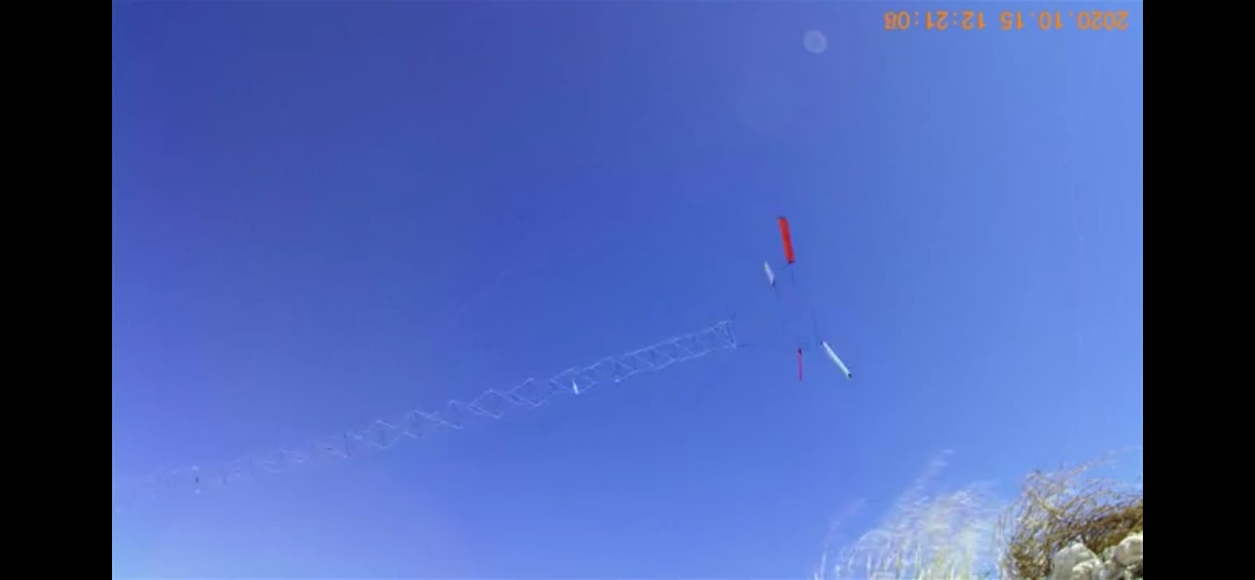
someAWE

By having a top section of limited tether length and then reducing the shaft to quite numerous small radius sections, the tether drag is very limited. The MTR value must be quite high due to the high value of \frac{r}{r_n}. Also, if a gust hits, each segment must find its new \theta_n to match the new desired torque \tau of the shaft. These \theta_n add up, causing the phase difference of the cartwheel at the ground and the kite rotation to become very large. This maybe leads to a very hard to control system, moment-wise. I have a feeling that from what we are seeing on released videos, maybe the radius of the shaft may well be increased slightly to reduce this phase difference. On the positive note, the shaft extends “forever” without essentially any added tether drag. Only the mass of the shaft may become an issue, causing waves in radial direction and in \theta. My guess is such a design is very dependent on accurate readings of the kite phase angle to be available at the ground. The shaft essentially is uncontrollable, so any waves must be dampened on either the airborne or ground side.

Single segment TRPT

These don’t have the issues as seen with the numerous elements of someAWE with waves in the shaft. The shaft does not have much weight other than the tethers themselves. On the other hand, such shafts have the inherent quality that they can’t be very long due to the way K_{MTR} depends on \frac{r_0}{l_0}. So to get around this, a huge cartwheel at the ground in addition to a tower is necessary for this to be practically feasible. Also, as the shaft does not have a convex outline, tether drag is significant, making it hard to get the TSR above 10.

1 Like

I would lile to add another concern.

When gust and lulls hit, the change in \theta also means a change in shaft length. This has a positive feedback effect that may be especially damning during lulls.

Reducing the T_N actively at the kites will maybe reduce the change in twist. This control problem is not well understood by me yet.

Choosing short stubby sections with high \theta will increase this effect. It seems the someAWE design is succeptible to this effect in particular. But also designs with passive kites that may not have the option of actively controlling the shaft tension.

Lots of food for research here…

1 Like

Did you mean concave?

Shafts thinner in the mid section compared to a straight cone have less tether drag. They are concave?

You are absolutely right.

A tilted tower? Please can you produce a sketch?

About TRPT my concern is the low potential of scaling of flying rigid torque transfer elements (weight, momentum effect…), excepted in the very difficult configuration of multi stacked rotors.

The only one fully soft TRPT, without any rigid flying torque transfer elements between the flying and the ground rotors, is Rotating Reel System. But it does not work very well.

I see a possibility to scale a lot by removing any rigid flying torque transfer element. Certainly the proportional height (tether length / rotor diameter) is low, but it is not a problem with a huge rotor. There remains the problem of the torque transfer ring, perhaps to be transformed into an additional wind turbine.

1 Like

As for lulls. I suspect that higher L/D will always help as the faster tip speed ratio will be less affected by a particular lull going through.
But yes there is as Pierre points out the momentum of shaft weight if there are extra element sections … I don’t think this is too problematic as the energy maintained in the shaft keeps the rotor spinning through a lull… Kite rotors can be back driven (powered up from the shaft)

It depends how we are controlling the (Power Take Off) PTO at the bottom of the TRPT.
Our plan for the next tests is to control the PTO rotation based on rotor lag angle data and precise rotor location (Shaft Length) data coming from the rotor.

The lesser drag of thinner lower section of shaft definitely helps build altitude of the rotor. The mass per length of TRPT will have to scale with a proportion of torque increase… to what extent…?

1 Like

My concern is the elongating shaft effectively subtracting wind from the already reduced wind.

To maintain flying speed one must increase glide ratio at the kite once a lull is detected. That means increasing lift in practice due to the high tether drag. End conclusion is that the plant cant run max efficiency as one needs a efficiency reserve for lulls.

Of course, with low twist in the shaft and low mass of the shaft, the time constants involved are very much reduced. Thus less need for a reserve.

Also higher mass of the kites may help keep the speed evened out.

When I come to think of it, running at different wind speeds should have the same amount of twist, as T_N will be reduced to match the twist. So with ideal control, one only needs to account for a change in rotary speed

Maybe

This is a very complicated problem, requiring many compromises to be made in order to succeed in real life situations

1 Like

Some quick data of the someAWE rig, source MAR3 — someAWE.org

image

I believe the wingspan may be 0.6 m each, then r is 0.9 m, r_0 is 0.20 m as are all other radii ecxept the last. So max MTR value is approx \frac{0.2}{1.5} = 0.133 judging by tether length 1.5 m for the last section. Each segment is tether length 0.28 m, allowing for max MTR \frac{0.28}{0.2} \frac{0.2}{0.9} = 0.311. There are maybe 30 segments to the shaft.

As a «twist» the smaller segments are pretensioned to a large \theta= 90^\circ so any change in T_N has less impact on tether length.

Still we see gusts causing waves travelling back and forth on the shaft. The kite end of the shaft looks like it acts as a mirror.

The MTR value calculated for the shorter segments may not be that good as the segments are not long and slender.

The wings are this foil that has 2D L/D of maybe 60. But a square outline and AR 4 should reduce that to maybe 5-7 for the wing alone (? guessing a bit here). Tether drag will reduce that a bit more.

Thanks to someAWE for sharing the design details.

What would you reckon is more efficient when stacking rotors onto TRPT?
A
Having a consistent shaft of small diameter go all the way up through the stack of lower rotors with each rotor well spaced and bridled onto the TRPT shaft.
Or B
Only having a small diameter shaft TRPT up to the first rotor, then stacking rotors with each rotor bridled to the last and the bridles being at near full diameter but being short.

Or other
It’s all going to be dependent on scales too of course

1 Like

Let me first just say that this is pure speculation coming from a person who never built a TRPT longer than 30 cm. And in the audience people who built really large and working shafts/plants. Take it for what it is.

I would be talking about shafts with compressive supports here, meaning rigid elements that could guarantee any radius [carbon fiber rods or inflatable structures most probably].

My starting point would maybe be looking at the “pressures” in the design

  • A: the shaft must be as long as possible
  • B: the shaft must be smaller at the ground side to allow a low elevation angle without a tower
  • C: the shaft should be lightweight
  • D: the shaft must resist buckling
  • E: the tether drag must not be too large
  • F: Elongation and twist must be controlled in gusts and lulls
  • G: Tether must be strong enough for all twist values in question
  • H: The shaft and the rest of the plant must be deployable
  • F: Practical matters, such as how much tether bending is acceptable and mechanical termination of rigid elements

I’m sure there are more concerns that are important. You cant just put an algorithm to figure out the right answer to this one. You have to discover solutions and build on them incrementally.

In general, it’s important to order these concerns by risk, high to low. First get the high risk items out of the way, then deal with lower risk later. That way you invest least before failing.

Most important/difficult: H

For this item, I don’t have much to add. Also, there has been little talk about this one. So maybe we should start talking more about it, in my opinion.

Medium important/difficult: B, C, E, F

Less important/easy: A, D, F, G

I put A here in the less important bag, though most would maybe say it’s the most important. I think the shaft length is just “you get what you get”. No point in trying to extend the shaft more than what the other concerns dictate. I think it is clear now that the minimum shaft length that is achievable by physics is no showstopper to using TRPT for AWE.

For B, the radius at the ground side: I believe some size of cartwheel is possible. The ratio \frac{r_{\mathrm{kites}}}{r_{\mathrm{ground}}} is very important for the mtr value of each individual shaft. The bigger the ratio, the stubbier the shaft segments.

For this one I would tend to think that a high number of segments is more costly to the design than a larger cartwheel and a small tower at the ground. So maybe make that ratio less than 10, maybe less than 5.

The shaft may taper to a nominal bigger radius as soon as elevation angle allows.

For E, the tether drag must not be too large: The tether drag is very dependent on the radius of the shaft. Due to the way tether drag works, reducing the radius by a factor x reduces the drag by x^2. For this reason I don’t see any good reasons to reduce most of the shaft radius to less than \frac{r_{\mathrm{kites}}}{3}. This should happen close to the kites, depending on the resulting effect of drag from the tethers and the need for larger compressive members at the kite rotation plane. Ideally centrifugal and aero forces should be enough to keep the kite looping radius apart during production, but there may be additional requirements from handling.

For C, the tether should be lightweight: This depends a lot on the mass scaling of the rods supporting the segments. That question may [maybe] be answered by answering; would you rather have one or two segments for a given shaft length.

The mtr value of the two segments with lesser radius matches the single segment when (K_1 being the mtr value of a single section and K_2 being the double section. r_1 and r_2 being their respective radii, l is the length of the section)

K_1 = K_2 \frac{r_2}{r_1}

Using the coarse approximation [assuming long slender sections] gives us

\frac{r_1}{l} = \frac{r_2}{\frac{1}{2} l} \frac{r_2}{r_1}

r_1 = \sqrt 2 r_2

Now look to the scaling of the shaft. I will assume we just use a massive rod and scale it by a factor \sqrt 2 in all three dimensions.

Source: Euler's Column Formula

F = \frac{n \pi^2 E I}{L^2}

We have for a rod

I = \frac{1}{12} m L^2

Giving

F = \frac{n \pi^2 E \frac{1}{12} m L^2}{L^2}

F = n \pi^2 E \frac{1}{12} m

The mass of the scaled two smaller segment rods are m_0 \frac{1}{2}^\frac{3}{2}, and the sum of two masses is m_0 \cdot 2 \cdot \frac{1}{2}^\frac{3}{2} = m_0 \cdot \frac{1}{\sqrt 2}

I don’t expect any reader to follow all these calculations, but I can conclude that the two smaller segments have less mass for the same moment carrying capability.

This leads to the conclusion that many shorter sections is better for mass. As shaft length and radius scale differently this will eventually result in a minimum segment length that is short and stubby. I expect using the exact equations would give an optimum shape to minimize mass while retaining the required mtr value.

Also keep in mind that the shorter stubby sections require fittings that have mass and that a spiralling tether must be thicker and longer, and thus also incurs a mass cost. These concerns must be weighed up against mass savings for the compressive supports.

My conclusion so far would be; if shaft mass is an issue, and for scaling it is probably one of the main issues, many shorter stubby sections should have the lowest mass. As these shorter sections also have low radius the tether drag is not expected to become an issue, nor is shaft length [besides its mass].

Though if you focus only on short segments and mass, concern F, elongation and twist, may become severe and put new pressures on that concern.

It seems to me someAWE is pretty much aligned to this analysis.

2 Likes

Great analysis! I agree with your conclusion (coming from a person who built plenty of TRPTs) :slight_smile: /cb

2 Likes


One of the lines has been removed from the mid section of this TRPT before a form finding simulation.
You can see the strain on the lines from green low to red high.
The lines to the side of the broken / removed line take the strain of the missing element.

1 Like

It’s a more pronounced support comes from the surrounding lines on a 6 line TRPT

Here’s a stripped back 5 line TRPT without the centre lines or central lift line
Still holds but looking a lot more volunerable

6 line clean

Now just to be 100% clear
The moral of this story is
Use TRPT kids because
You can break lines without endangering lives

1 Like

I remember Roland’s observation that when one line breaks, other possible lines follow and break too.

I think it is true that if you have two or three lines, for sure a tether rupture requires a «Plan B». Having >six tethers, you may overdimension the tethers slightly to allow for a single tether failure. I think its a good idea and a good thing to consider. Definitely a plus.

That being said, the response of the shaft on rupture may be complex, and even spread of load may not be guaranteed after such. And not all geometries are as suited for having redundant tethers, though they may still be viable by having good control of tether condition.

1 Like

Roland will have said other lines will be more prone to break.
And I’d agree.
Not other lines WILL break.
That I’d have to disagree with having seen it happen otherwise. e.g single line elements can break.

Best to over-dimension them all as Tallak points out