The place to find expert discussion of turning rate advantage is on Kite Forums and Blogs, not AWE papers. Sample-
Our top classic kite scientists are the best, in any case; Hargrave, Chanute, Wittgenstein, Rogallo, Barrish, Payne, McCutcheon, Loyd, Roeseler, Lang, Culp, Ockels, and so on. No one should expect as much from “PhD puppy-mill” kite science. This is well known on the Old Forum-
From: dave santos
To: Yahoogroups
Oct 5, 2017 at 6:04 PM
A few years ago kite surfers identified kite high turn rate as a critical competitive edge, particularly in gnarly dynamic freestyle conditions. For decades, performance soaring has understood tight turning in thermals as desirable. As kitesurfing and soaring are energy-driven, we study every such anecdotal heuristic in AWE, sooner or later. This is a belated start at analysis of Power-Kite High Turn Rate in our AWES context.
Power-kite tight turn capability seeks to maintain high velocity out of the turn. Better-kite can thus zip back and forth across the power-zone of the kite-window, at highest extraction capacity, while not-so-good-kite burbles the turns. Two familiar factors are especially key to high kite turn rate; low inertial mass, and high lift coefficient…
Expect a high turn rate kite wing to have modest aspect ratio (birds like swifts fold wings dynamically to low AR). A long wing is better suited where the Wing Span to Kite Window Width ratio is low, as a design law to guide us in matching wing to window."
Lots of AWES airspace and land-footprint density references over the years, well before 2017 turn-rate analysis. This quote from 2011, TACO1.0-
"Dense Arrays- Super Density Operations (SDO)
A major class of TA is cross-linked wings in arrays. Such arrays are calculated
to utilize airspace up to a hundred times more efficiently than single-line AWES.
The “tether-scope” requirement of single-line systems means they operate too
sparsely to scale greatly.
Multiline Arrays also have key safety advantages over single line systems.
Redundancy of tethers makes flyaway safely improbable. Land and airspace is
conserved, minimizing obstruction issues. Conspicuity is greatly
enhanced."
Finally, a recent Old Forum kPower post, referencing your interest (2019 Jun 6 at 8:08 PM)-
"[AWES] kPower Testing showing SS Power Kites Turning Tightest under Power
A few weeks ago, at Pierre’s suggestion, the subject of kite turn-rate recurred in the evolving context of maximizing airspace. kPower started working through its encyclopedic power kite quiver to compare turn rates, to validate heuristic prediction in favor of slower, lower-mass wings.
Using parafoils for session comparison, as the hotter higher-mass baseline, SS kites of the three major types (NPW, OL, and PLSS) were observed turning tighter and faster by equivalent wing area and wind velocity. The hotter parafoil somewhat overshot the heart of the Power Zone, where the SS more closely ruled, especially when both fly short-lined. With Rigid Wing kites based on super-hot gliders, the wide-turn effect is even more pronounced, as any glider pilot can predict. Hot wings can be made to roll and pitch a tight turn, but its an extreme maneuver that depowers and slows the hot aircraft, which then has to re-accelerate up to speed.
This anecdotal kPower result will be easy to directly confirm by third parties. It suffices to watch power kite and glider videos for non-dimensional pattern-flying laws. Its not just the higher inertial mass that makes turns large, but also common lack of vertical keel and/or wingtip/winglet area, so drastic roll-pitch input is needed instead."
In summary, power kite pros naturally evolved high turn rates and high airspace density twenty years ago. This is still advanced AWE knowledge, hardly yet published academically. kPower is the closest AWE venture to expert kite culture in all its variety, as well as closely following academic AWE R&D. Its really all one fantastic AWE world.
I will nuance strongly my answer in that kPower “land footprint” is different as kPower envisaged secondary uses and the presence of inhabitants below AWES (I remember some sketchs and texts of AWES above towns) unlike me. Even you criticized my poster in AWECBerlin2013 about land and space use.
I precise it again. There is no scientific paper about the power to space use ratio. Beside it the turn rate was studied by classic kite players, but not for the purpose of a better power/space ratio for an AWES to generate electricity at utility-scale. I see the turn rate as an element among others to improve this ratio.
It was true several years ago. It is true now. I am the only one to regularly say that a high efficiency by crosswind flight per wing area is nothing when several km² are used, preventing secondary use.
When a second player will understand it, a step will be reached.
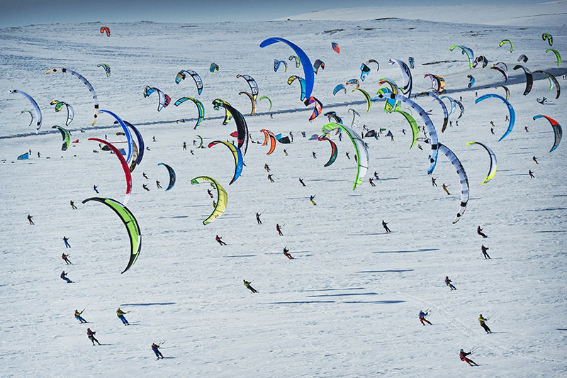
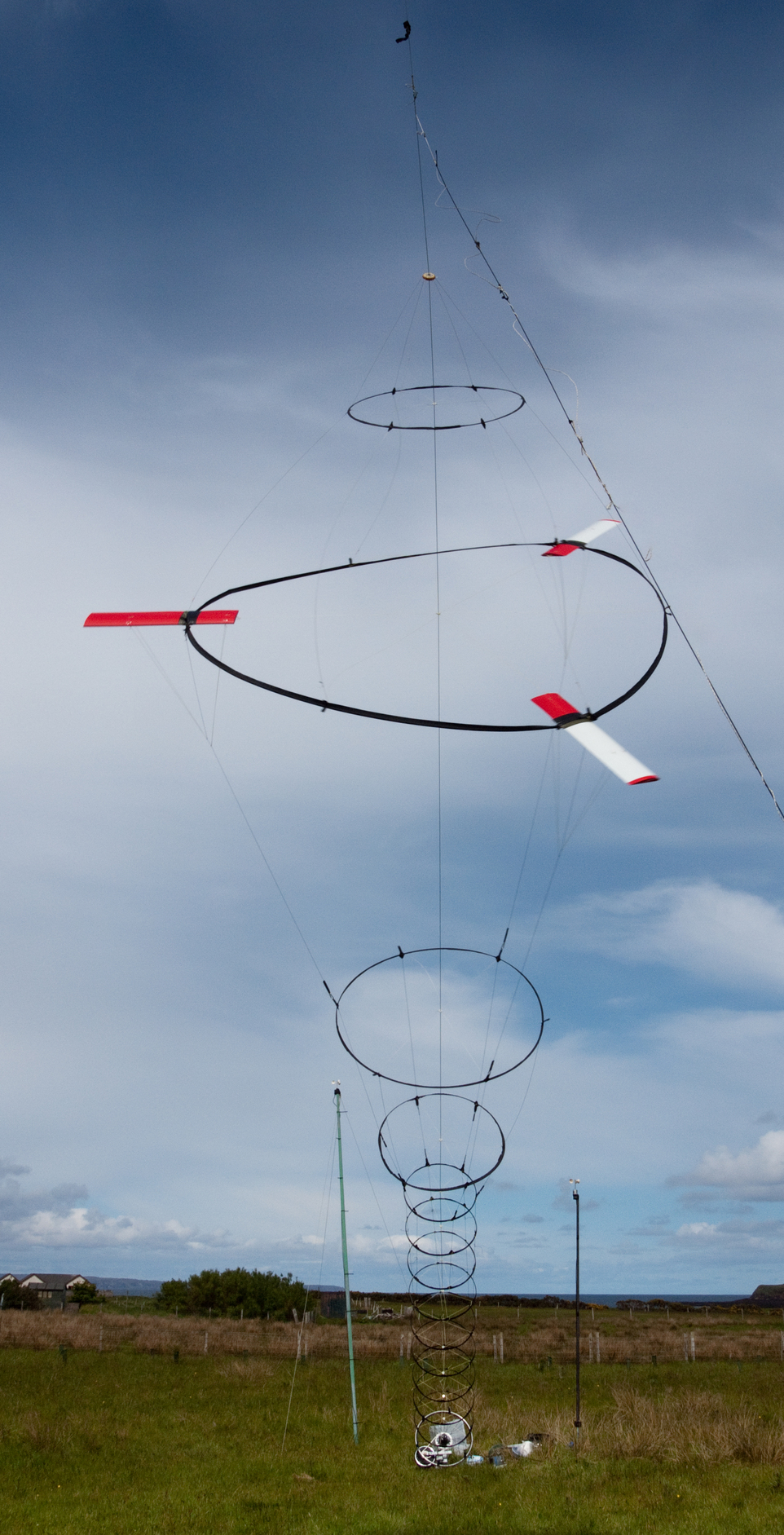
Indeed the photo shows a multiplicity of power kites with short tethers (10-20 m) and driving the users. It is very different when the tethers are 1 km length and with stationary rigs. If the proportions remain constant as I advocate, the wings would be gigantic, which may be necessary for a good power/space ratio under acceptable control conditions. Such a configuration can be studied as a mean to improve the power to space use ratio.
Multiline Arrays could perhaps be a mean to maximize the space, but in this case a forest of long tethers would hardly be manageable. And in the same time you indicate the power-to-weight ratio as the first one. I consider things in another way: the first ratio is the power/space ratio, then multiline Arrays is a (not the best imho) mean to reach this ratio. Other means can be multiline-single kite, and even single line (in several parts)-single kite.
I agree. There are relevant observations and analysis. Thanks.
I precise that I wrongly or rightly interpret a “rigid autogiro turbine” as a not yet tethered device like an autogiro or something like a wind turbine, thinking it uses only its own space with its swept area.
But as the autogiro is tethered, even when it is stationary, the tether could move the autogiro far away according to wind conditions. So the tether fully modifies the topology within the environment of the complete device.
DaveL and GrantC’s SkyMill is our best tethered Autogyro AWES model. I helped them test prototypes on the US NW Coast. Not much airspace was needed.
AWES kitefarms require a forest of tethers as much as kite sport events. However, instead of complex individual control, network interconnection aloft (topological stability) is simpler, and enables passive dynamic stability, including lattice waves. Many such stable topologies work without fuss, like drop-stitch construction as a model. Its the common many-single-line topology that requires the greatest spacing and most concerns.
You are finding that absence of AWE scientific papers is not always absence of AWE science. Initial AWE spatial density and turn-rate science exists in the texts cited. Do not wait for AWE academia to catch up, just keep moving ahead.
Land footprint is not just one set of crude assumptions. The same footprint unworkable today by crude art becomes workable tomorrow by superior art. That is how to analyze footprint maximization, based on all critical factors. Yes, AWES will someday fly over populations, just like most aviation. Kite Networks have desirable advantages for populated places. One can walk around the 2000 kites set on arches much more confidently than if they were each single line.
Thanks if you find earlier references to AWES space maximization issues than those I provide.
Thanks for the references. I will pursue in the present topic which seems to be more appropriate, Makani’s wing being a special case of crosswind flygen rigid wing, multiplying the risks. It can be a reason why both Fig.4* and 2.2.1 Zoning concept in [2] and Fig. 16.6 and 16.4.1 Spacing of Units in [3] concern “flexible wing systems” ([3] mentioning also rigid wings in the introduction, but not elsewhere) as you indicated. By this one can deduce the acceptable risk for flexible wings would not be as acceptable for rigid wing. It is a secondary point which should be more studied.
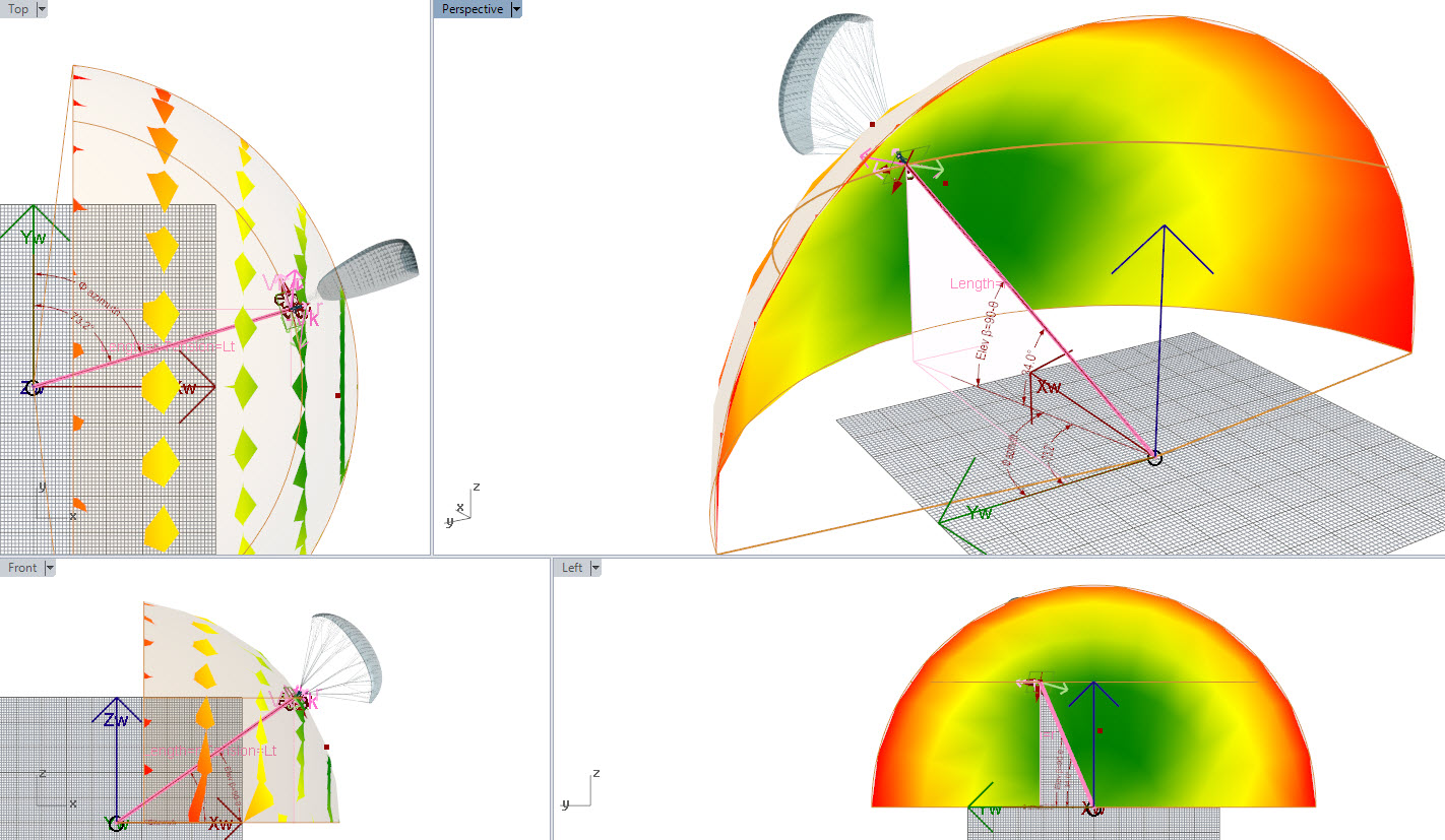
Now let us come to the main points. Fig.4 and 2.2.1 Zoning concept in [2], and Fig. 16.6 and 16.4.1 Spacing of Units in [3] are similar and both describe a sort of tilted and reversed cone delimiting the danger zone, allowing some uses under the kite flying. IMHO it is quite unrealistic:
Wind direction is assumed to be the same for the whole kite-farm. But various winds in direction and intensity can occur in each place of the kite-farm, leading to a likely collapse. The probabilities of such variations could be studied, combining stochastic and real wind data for example, or lead to more spacing, or even to the implementation of a single larger unity.
The safety issues are mainly computerized. The scheme of a farm of crosswind kites lack passive safety. The computerized management failing would likely lead to a full collapse.
Knowing that the tethers move fast under several tons of tension, that at a low elevation angle of an average of 30-40°, people under such tethers would likely not be accepted. I remember safety instructions from Enerkite during AWECBerlin2013 for the few kW-range wing: “nobody under the kite!”.
Currently the industry is only about preliminary testing and theoretical studies, excepted @Kitewinder.
I am afraid that my estimate is well below the security imperatives that will not fail to occur, at least for a while. Indeed a fall zone should be added.
A tether of 1 km is a little like a tower of 1 km, but in addition the rope is moving and is under high tension. So more compact designs should be studied. But it is only my opinion.
Figure 4* [2] from V. Salma, F. Friedl, R. Schmehl: “Improving Reliability and Safety of Airborne Wind Energy Systems”. Wind Energy, in production, 2019. doi:10.1002/we.2433 . Preprint accessible as pdf :
Yeah, I must be rubbish at getting this message out… I’ve been trying to communicate this for quite a long time…
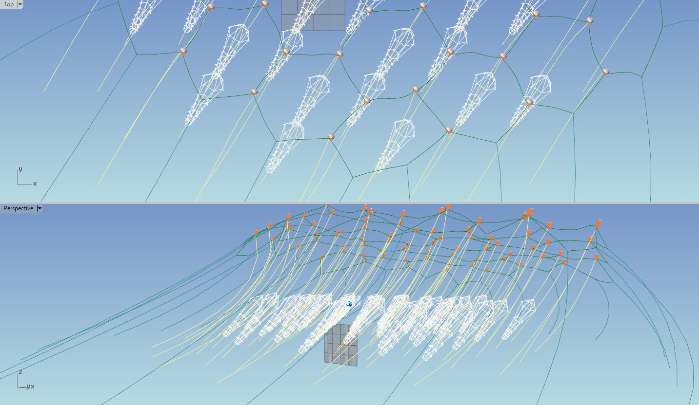
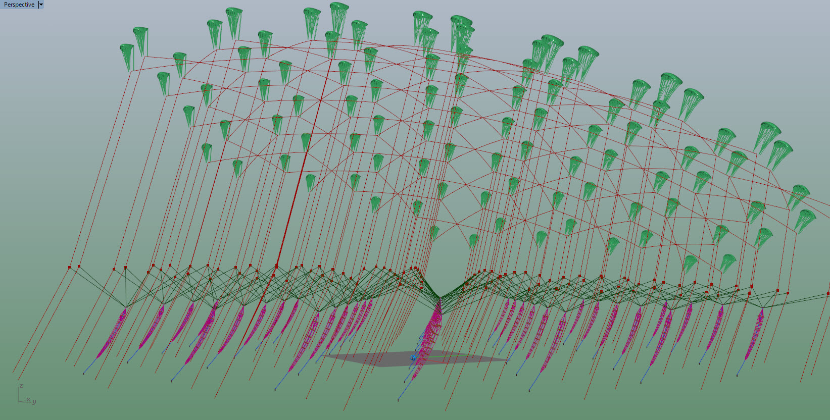
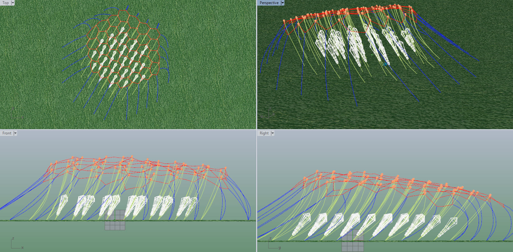
Refresh of old drawings a little more polished to show how networks improve land and air space usage.
The elevation on these stacks is shown too high
Rod correctly identifies networked kites as the highest theoretic power-to-airspace AWES basis.
Networked kites with many-connected topological-stability also solve unit-kite runaway risk, single-line unit-kite scope-interference, and promise best overall plant economy-of-scale. Networked unit-kites can also have the highest turn-rates, densest spacing, and may in large numbers spontaneously develop coherent lattice waves, for powerful pumping outputs.
Wubbo’s SpiderMill is a 2011 networked kite concept offering these inherent virtues. kPower proposes cross-linking SpiderMills into metamaterial networks. Pierre’s Ortho-Kite-Bunch is another early AWES network concept. Rod’s kite network concepts cover a further range of ideas. Its time for serious research into high power-to-space AWES kite networks.
Another commonly overlooked advantage of this awes is the constant output without lines which wear out by running over capstans, pulleys, fairleads and drums.
In terms of power to space… The modularity also lends itself to changing land use cases… the ground footprint could be rearranged depending on… season, late payments … other
The best thing about kite turbine architecture efficiency is the match of deployment of material, to its potential to work the wind power window.
A system with 1 kite here sucks VS A system with a network of kites working right in the power zone.
That’s level 1 efficiency advantage to networks
Then level 2 is the farm stability
I spent last week snow-kiting, we should all be doing it and flying more kites more often.
Power, tension, turn rate, control authority all ramp up in that green zone… Get in there.
Kitesurfing (see the video below), kite buggy, and other similar AWE sports lead to a high power to space use ratio resulting from a higher density. And yet they are crosswind systems. The main difference with usually intended kite farm is the absence of figure-eight or loop, the wings going crosswind in the same direction. As a result these AWE systems can be stacked at a high density, like static kites, unlike figure-eight AWE systems which require more distance between unities.
Trying to work out the space used / power generated for a Daisy (Kite Turbine) is tricky
The same 3x5 network configuration can be configured very differently.
Lets say a lifter kite operation takes a given radial area and volume around a ground station…
in these examples I’m using ~2.6 hectare
The same lift is assumed to be servicing these three Daisy configurations.
Which one of these configurations is the most reasonable?
I had a question about these pictures above and I should clarify here…
I’ve been trying to look into the farm MW/km2 potential of Daisy
What I showed in the pics might not be very useful as it would depend on arraying the cylinders shown and the wake intensity generated by the 3 configurations offered.
Wakes from Daisy are potentially less extreme (even with the extra inner tip) as the system is more efficient in low TSR ~3.5 and the hollow axis will allow better wake recovery.
In the pics the cylinder is the volume containing the lifter at operating height around the ground station
The same lifter height and cylinder volume for each configuration.
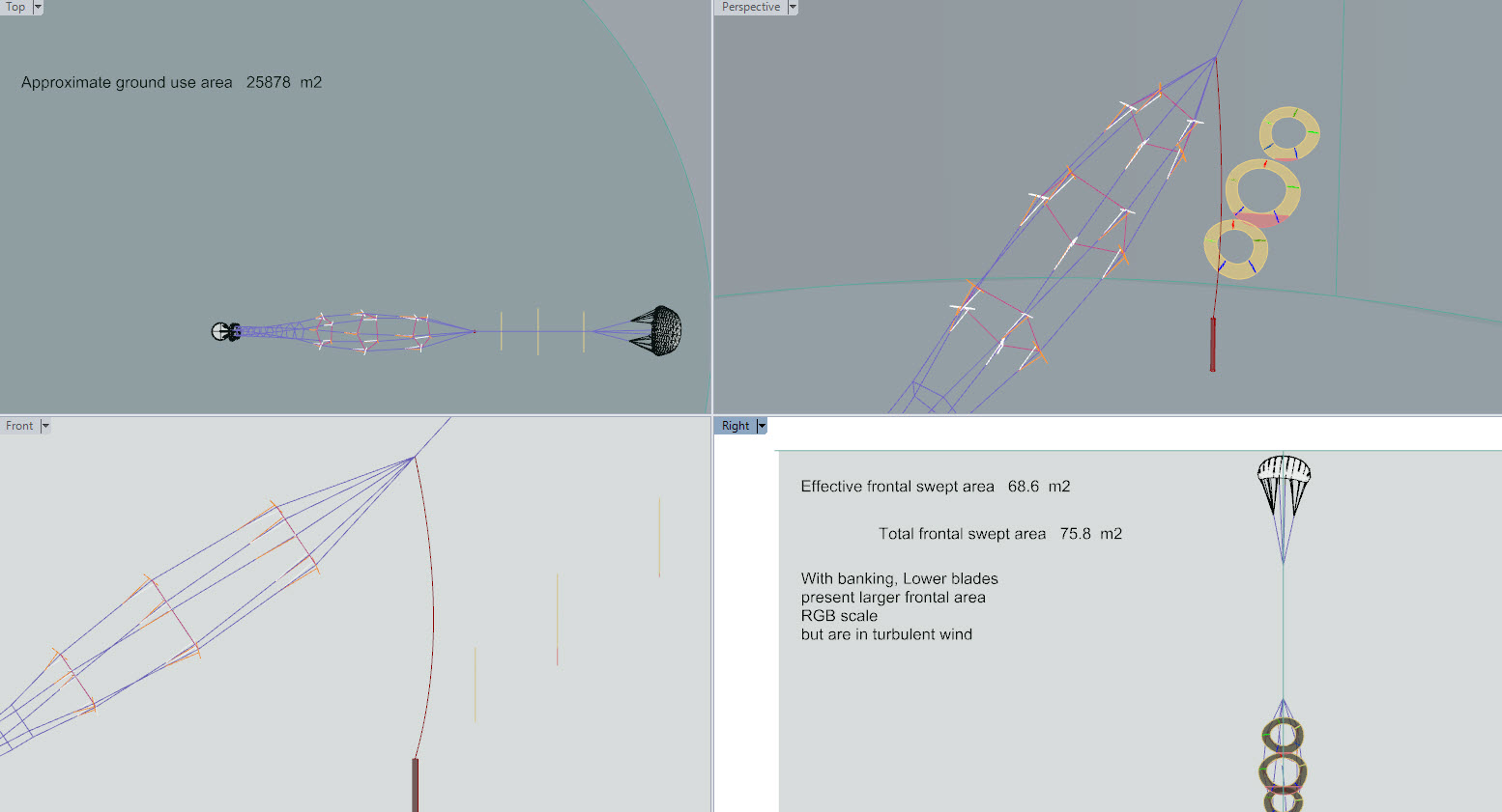
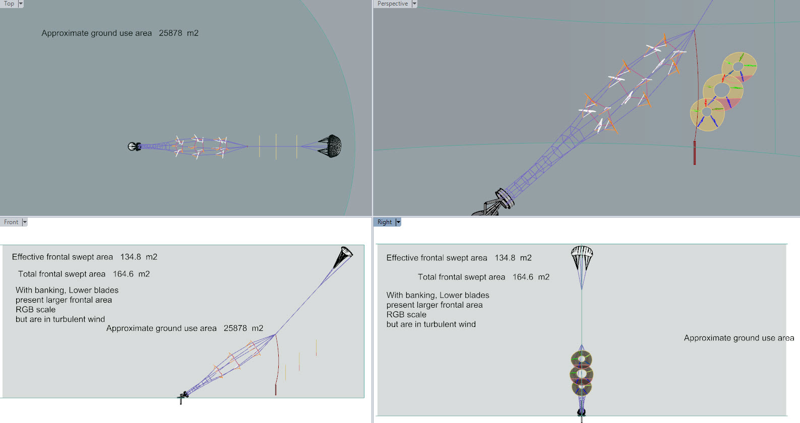
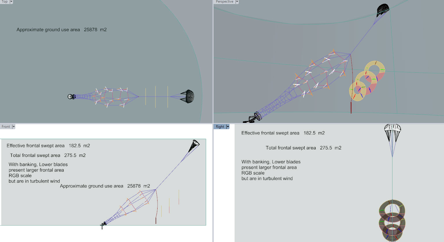
The are 3 configurations of Daisy. Yes, Each Daisy is 3 rings stacked with 5 kites on each ring.
The 2 upper blade anulus flight paths are shaded where they will fly through the wake of the lower rings.
Because the blades are banked, outer tip down, from the plane of rotation the flight path is less apparent to the wind at the top than the bottom of the otherwise ring shaped flight path.
The lower the kite blades are in their path the more flat they are to the plane of the oncoming wind…
The Red Green Blue spectrum colouring of the blades shows how much relative area of the wing is flat to the oncoming wind.
In terms of the whole system these lower down blades would tend to pull the system back and potentially down. The good thing is they are in a depleted wind resource relative to the top blades which are pulling up.
The calculation shows the difference of the relative areas of path in the plane of the oncoming wind.
So the various configurations, run in the same volume (same field area) would have a varied effect on wake intensity / energy depletion and the potential for farmed MW/km2
but which would be most efficient?
I’d like to add a data point I read today in the Norwegian magazine tu.no.
It seems the HAWT windmills use an area proportional to the output power.
I 2019 beregnet de den typiske arealbruken per MW til 100.000 kvadratmeter (m²) eller 0,1 km². I Norge er det imidlertid vanlig å installere turbiner på 3 MW, som da vil legge beslag på 0,3 km². Med utgangspunkt i Miljødirektoratets tall, kan vi dermed fastslå at det er plass til tre vindturbiner per kvadratkilometer, ikke bare en, slik Miljøvernforbundet hevder.
In 2019, they calculated the typical land use per MW at 100,000 square meters (m²) or 0.1 km². In Norway, however, it is common to install turbines of 3 MW, which will then occupy 0.3 km². Based on the Norwegian Environment Agency’s figures, we can thus determine that there is room for three wind turbines per square kilometer, not just one, as the Norwegian Environmental Protection Agency claims.
I guess AWE anyways fares worse, though it is interesting that the energy density of HAWT reduces with scale at the same time that economy of scale is very important.
The article also mentions that the area use of windmills is considered by some to be a big issue:
Motstandere av vindkraft hevder vindkraftverkene krever enorme areal. I en mye delt video på nettet hevder Miljøvernforbundet at verden årlig må bygge ned et areal på størrelse med halve Norge dersom vindkraft alene skal brukes for å stabilisere verdens CO₂-utslipp.
Opponents of wind power claim the wind turbines require huge acreage. In a much-shared video online, the Norwegian Environmental Protection Agency claims that the world must annually reduce an area the size of half of Norway if wind power alone is to be used to stabilize the world’s CO emissions.
Though I’d like to emphazise that these numbers are debunked.