Just wanted to share a reeling power transmission for hovering [snickers] AWE designs.
The new thing is instead of an endless loop, you have two reels on the ground. You will need to alternate now and then, but the benefit is that the length of the reeled out tether can be adjusted on the fly, for easier launch and landing.
With some gearing, the generator can surely be shared between the two drums.
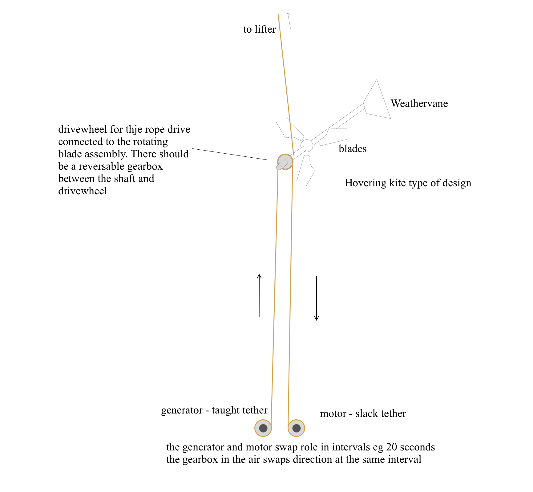
Edit: I realize this was not very clear. The aim is to collect energy in the airborne pulley eg by a gearbox connecting the rotating blade assembly to the pulley wheel. Then reel the tether back and forth, collecting the energy at the ground. Compared to a reel with a looping tether, the operation is the same, except the loop runs forever while the dual winc must alternate the direction. Also, new and improved drawing
it is interesting indeed because it allow to change altitude easily. but how does it works in generating phases? has drawed, it looks like a yo yo kite system, far different from having a wind turbine up there
The thought was it would run for x seconds then reverse. Of course the airborne side of things would also have to be reversible… i think maybe a ratchet kind of mechanism could do that
The airborne assembly should stay hovering at a fixed place.
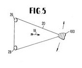
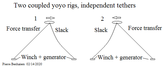
This design is the same as Payne’s patent fig. 5 apart the pulley at the kite level, the two drums with generators replacing the generator + anchor and the pulley + anchor, and the confusing “hovering” term replacing the appropriate and well established “crosswind” term.
Payne’s figure relates to a pulling energy transmission from kite to alternating winches. Its basically just two yoyo winches strapped to a common kite.
My figure describes a system where one drum reels out and one in at the exact same speed. But the reel out speed is not related to the blade flying speed, as this is a reeling system. At the airborne side, you are not seeing merely a pulley, but also a wheel where power is transferred from kite to ground. Power transfer from blades to that wheel probably using a gearbox.
That construction enables easy deployment as total tether length can be easily changed. But that is not useful once the system is running.
Edit:
I do admit that on closer thought, Paynes no 5; is it reeling or pulling energy transmission? is an interesting and not straightforward discussion. I still stand at pulling like initially. Related question, is it hovering or bounding? depends on flight path. I think it can do both
Sounded like you had leading edge blades driving a 3 way capstan loop developing there Tallak
Like a mechanical Makani driving lines.
Sounds very tricky but cool. Please build one
The “reversing laddermill” comment was a mere flash conjecture on my part, as I looked at a drawing showing only a tether rope, but no blades or working surfaces. I was adding an assumed detail of blades somehow driving the rope, but on second glance I have to say I do not see any fully workable drawing or description here, since it contains no details of how any working surfaces would power it. What am I missing?