What is possible with Payne's patent US3987987 figure 5?

Hi Tallak, thanks for asking.
It’s an endorsement of actually trying things, rather than endless online speculation through typing on a keyboard.
What, with over billion dollars wasted so far, nobody bothers building even the most rudimentary version of the most straightforward “crosswind kite” configuration imaginable? People just talk about it for 12 years and ever build one? WTF? What’s the matter, not enough idle interns yet? Not enough volunteers in Texas? Seems that the population is being dumbed down by computers. No more machine shop skills. Forget that troublesome, challenging 3-D world. Build something? The main skill I see now is website development, meaningless renderings, and how many people you can fit into your group-selfies.

1 Like

Better than no video at all, possibly suitable for an elementary school science-fair effort, cub-scout project, etc. It would be nice to see a serious effort.

1 Like

Oftentimes people figure out that something will probably not work great on paper before they actually spend months to get it working. This is why something ready built and working is worth a lot more than a nice idea.

For the Fig5 design, i am still unsure if it could work. The design is interesting for sure, but I am guessing there might be some showstoppers in there that are not apparent from looking at the patent. So the reason it is not yet built could be that building such is not a great idea in the first place.

1 Like

Dave Santos built and tested the device on the figure 5. The video is on the present topic in two comments and on another topic (Figure 5, Figure 5 compared to pulling force, kPower LLC filing - #58 by kitefreak). He built also a version of the tri-tether.

1 Like

I think what confuses a lot of folk, and also is the biggest potential for tangle, and efficiency loss, and control overhead in this idea …
Is that there is different tension on the 2 sides of the loop…
Lets say we have only 1 generator (Left Hand Side) and one perfect pulley (RHS).
We have 1 loop of line with 2 (or more) tension levels because the pulled side of the loop (LHS) goes over a drum or a capstan (LHS) which has to restrict the movement of the rope to extract energy…
You can’t push rope. So the end going toward the pulley (RHS) … well it’s not doing it very effectively with push, it’s being pulled. Which uses more energy. Along the rope there are different tensions where it’s movement is being restricted.

The kite will be moving… but mostly with respect to the (LHS) capstan. Now with 2 capstans… You won’t have as much tension control authority from the (RHS)

Getting it to go crosswind… Like actual cross-wind not science-crosswind which is real world cross-off or a broad reach… #AWESScienceSucks. Getting it to go crosswind … That would take a lot of cable tension and length management equipment between the 2 sides.

Of course there’ll be friction on both sides. Smaller wheels will mean lots of line wear.
So the end of the loop pushing in toward the (RHS) That’s going to bundle up and snag horribly if you take too much power out on the (LHS)…

It’ll work when you don’t take full power out… But what about gust and lull handling?

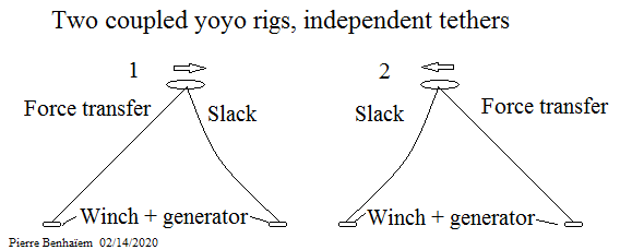
Disconnecting the tethers avoids simultaneous traction on the two elements on the ground, in a similar way as for Tri-tether plant with independent stations. However, the device shown below does not adapt more to changes in wind direction than the device shown in FIG. 5

Coupled yoyo rigs with independent tethers

If you want this, I would say whats the point unless both lines are somewhat taught. If you so that you can have crosswind linear motion. Otherwise is it not just a complex yoyo design?

If you use two motors, there are conversion losses. Even just creating a static force (zero energy at zero or near zero tether speed) may incur large losses. This is why pulleys are better.

But balancing two or more tethers like this with pulleys is a bad thing because all that force+counterforce must be generated at the kite then transferred to the ground. So if you regard tether drag as a large effect, this already sounds bad.

The topic is “What is possible with Payne’s patent US3987987 figure 5”, just as the neighboring topic is “Tri-Anchor Tri-Tether AWES Unit-Cell”. So my propositions have to be considered in regard to the devices discussed on these topics, not in regard to the full AWE field.

As I indicated, these devices with several anchorages are complex and likely not viable whatever the variant implemented. As I am not the type to give a mixed opinion (as much not to give an opinion at all), the more I analyze these bi or tri anchored devices, the less I see them a positive future.

The yoyo installations as they are generally studied seem to me both simpler (only one station / kite /tether) and more efficient in terms of force transfer and management. Which is not to say that I think they are viable.

That said it is quite possible to obtain a slack tether with no transfer force when the stretched tether is longer during its reel-out phase. The expense of energy in alternate reel-in phase is equivalent as for current yoyo rigs, knowing that a continuous power is aimed. Is it good for all that? No, but I think it is the only way to actually transfer the kite pull, unlike pulleys because they are connected by a part of the tether network, the assembly preventing a correct transfer of the kite force.

The main benefit I see from using the pulleys as shown is the minimization of the tether drag issue as the kite will not go very fast in this tether yoke.

How about a rope drive stretched along the ground with the tether of your kite attached to the rope from the rope drive? That’s what figure 1b reminds me of a bit. To avoid the tether deforming the rope too much you can add bridling.

I’m just talking about two pulleys separated some distance across the wind, a long rope loop, a generator. Try two pulleys before worrying about three pulleys.
You could build it and run it faster than doing a single rendering.
Budget? Probably in your pocket right now if you already have a kite. If not you’d have to spend a couple hundred. Entire project could cost less than $1000 using decent components.
Again, most configurations could be built and tried with less effort and money than even just applying for funding. Nobody bothers.
What’s so hard about it, finding pulleys? A rope? Suddenly no generators exist?
Or is it that you can’t do it from your i-phone?

1 Like

Dave already built a working prototype (video below again) of the US3987987 figure 5 AWES as I repeat. Please @dougselsam could you read the other posts before comment?

1 Like

Not endorsing this idea. But first testing some aspects of it could be very easy. You don’t even need a remote controlled kite, like you would think. Just pull the tether yourself, by hand or with a car or something. Then see what breaks or doesn’t work.

I am not sure to understand. Please @Windy_Skies can you provide a sketch with the rope drive, the pulleys (?), the rope from the rope drive, and the kite? Thanks.

I forget what it’s called but I think you talked about this often and there were or are even some companies pursuing something like this:

You can build a miniature version of it and pull it around with your fingers to see how it behaves and how you should pull on the string to minimize rope wear and maximize efficiency. Maybe put chalk on the tether and see how you can reduce the fouling of the pulleys with the chalk.

You can of course also make a miniature version of any system you are interested in. I think it’s one of the best ways to learn.

1 Like

In my opinion it would work back and forth like a linear track (NTS video below), or rather two linear tracks side by side with a kite for each, but being cheaper, and not requiring a moving generator as one pulley would rotate the generator, as for a ski lift which comprises a motor instead of a generator. The kite tether attach moves perpendicular to the wind on the pulley-rope-drive, as for the wagon on a linear track. The kite force transfer would be correct (unlike figure 5 for what I think) what I verified manually.

A carousel with a rope driving pulleys (or a cableway-like) would be perhaps also possible and has be evoked by Dave Santos in the old forum if I remember correctly.
Carousel with a circular rope driving pulleys

Yes that is the kind of configuration I’m referring to. One long horizontal loop, pull it back and forth across the wind with a crosswind kite to get crosswind kite power, if crosswind kite power is what you want to pursue.

Pierre: I believe a more carefully-constructed demo would need to be built to show potential. No substitute parts, such as a skateboard, but a real model of the actual configuration under consideration. I’d suggest a fixed position for the generator (like the drawings) that could be driven by the rope-drive concept we’ve read about so much for the past 12 years of internet-typing and flying kites for fun. Instrumentation could be applied to measure output if any version looks like it is working well enough to bother measuring.

Maybe these guys could help:


Check the video starting at around 10:00
2 Likes

At 11:00 precisely. This system describes a conversion from a rotational motion towards a linear motion via connecting rods. It is the reverse of the conversion of a steam locomotive.

If we add a second pulley and a rope drive between the two pulleys, then the kite tether driving the rope drive, we obtain something like the rope drive sketched by @Windy_Skies, excepted that the pistons and the connecting rods are replaced with a generator driven by the first pulley.

In any case, the rope drive on the ground seems much closer to the NTS linear track than of US 3987987 figure 5, especially with regard to the transfer of kite force to a single mobile point (here the kite tether on the rope-drive).

Thanks, I hadn’t heard of NTS before. Looking at that it occurs to me you could perhaps make it so that the tether(s) don’t actually have to go around the pulleys. You could also make the pulley without the generator attached to it mobile, to be able to better orient the system to the wind.

As a sidenote, if I understand things right, one problem with that setup is that every pulley is less than a 100 percent efficient. Assuming a pulley is 97 % efficient you’d get at least an 1-0.97 ^{10} \approx 26 \% efficiency loss from using 10 pulleys.