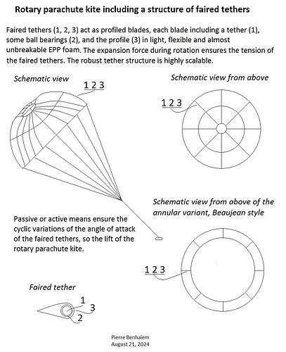
The canopy of the rotary parachute kite includes faired tethers which constitute its structure.
Its solidity is low, and the profiled faired tethers are expected to provide a high tip speed ratio.
If the faired tethers are fixed, no positive lift is expected, although axial thrust and torque are provided with rotation. In this case, a large lifter kite would be required.
But if active (mini jacks at the ends, controlled by servomotors) or passive means (using gravity and/or air pressure by apparent wind) allow to cyclically change the angle of attack during the rotation (not easy, even difficult), lift could be expected, and the rotary parachute becomes a rotary kite, usable perhaps for reeling or torque transfer TRPT or flygen (turbines in the circular basis of the canopy) AWES, maybe in all sizes because the used material (above all tethers, and perhaps also EPP foam) is both light and robust.
In a way this rotor could evoke Dr. Beaujean rotor with its thin blades.
Faired tethers have been well studied, in particular with the content of one of Makani’s patents:
[0025] A wing shape only minimizes drag if it is aligned appropriately with the wind.
We could add that if the “wing shape” is not aligned from time to time (during rotation), lift could result. And we are talking about distances of several hundred meters for Makani tether.
We can then imagine the degree of scalability when these faired tethers form the skeleton and the single structure (excepted the transversal ropes to adjust spacing between faired tethers) of the canopy of the rotating parachute kite.
Until now generally we were thinking long tether and relatively small and fast wing. Afterwards shortening the tether. And now the wing and the tethers would become one, if not for the additional tether(s) going towards the station.
Now only tests could allow us to know if this is really feasible, and to what extent.
A preprint is also available: Rotary parachute kite including a structure of faired tethers, DOI:
10.13140/RG.2.2.32706.80325


