The easiest way to ditch rotation is de-power, just as you imply the leading edge points down the line to the ground station at all points on the rotor. This is most easily actuated by maintaining tight leading bridling and releasing trailing bridles. Whether in wing or from a bridle point pod, powered or force limit driven… I also really like flex power smoothing like a windsurf wing.
The kites at the top of the loop will normally experience faster real wind and be travelling slightly into wind for faster (more forward) apparent wind
Heading down and slightly downwind shifts AoA back slightly. This is a substantial shift of AoA at lower speeds. I reckon it’s a funny tade off between max speed wings and foil shape. rounded leading edges normally tend to cope better with larger AoA shifts but speed really helps too… We can always speed the rotor up from below with a torque connection if needs be… As demoed on our rigid tests.
You’re kinda talking yourself into the solution here… Say we launch 10 (or 50) fast blades on each ring, then yeah increasing the diameter helps reduce rotor solidity thus making the rotor more efficient for the area it sweeps (which is now huge)
Excepted for depower by reversing, the kite being held only with the centre line. But that applies for Rotating Reel with only one (perhaps two) layer(s).
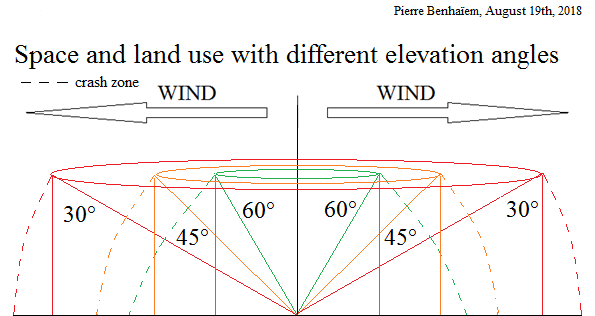
The tether defines the crash zone if it doesn’t break.
The rotor could be made adding several (flexible) wings end-to-end. A large rotor can allow a better maximisation of the space use, in a similar way as a rotor for a windmill.
This statement concerns the material, but not the space/land use. One can have a very cheap AWES but as the tether defines a huge area the space/land used can be very expensive as no secondary use (fishing, passage of ships, farming) is possbile excepted in some limited cases of strict schedule of both uses.
To be clear using a (even) 40 m span wing with a 1 km tether doesn’t sound for me.
1 Like
Where you have a lifting network, the motion and position of each kite is dependent on the normal rules, and also strongly influenced by any top net tension resulting from the position of neighbouring lift kite nodes.
This has an aggregate smoothing effect.
The average azimuth line angle of the network will result from the recent wind direction across the whole network field. This effectively reduces the swing you would normally get from turbulence.
Too much torque is deadly for a soft shaft.
Yes, centripetal forces are very small compared to tether forces. Much more likely that bank angle is used to keep the structure “inflated” to stop crushing especially in lower layers being driven from rotor rings higher up a stack… stacking rotor rings has proven already to be a great way to increase efficiency and scale the power from 1 network turbine… and Power doesn’t depend on radius, but can be increased by the most efficient sweeping of a larger radius. e.g. keeping the wing at 2/3 it’s glide ratio. Adding banked wing sections to maintain outward tension of the ring will help…
And nobody wants a rotor that’s all torque and no action (excuse the pun and simplistic chat)
Yes, we’re working with a soft rotor stack and there are definite circumstances which will kill it… Too much torque destroyed my 2 of the smaller diameter rings (old fibreglass ones) at the top of my torque tube stack when the generator demand ramped up too suddenly the other day.
The transmissible torque depends on, geometry from ring to ring (radius, radius and separation), L/D of the kite set (line angle), line tension, how well rings tolerate compression
Coning the rotor “shaft” (soft shaft?) down to smaller diameters in the lower sections helps to reduce flying weight and can still handle a hefty amount of torque using only thin rods. The smaller diameter rings do have to be closer together to maintain transmission. The advantage here is a much smaller ground generator and you don’t need active reeling of continuously changing line lengths … Lines are set length and don’t wear by running over spools, capstans, fairleads etc
… and you wouldn’t want the old carousel concept tipped on its side pointing at your kite.
Kites can be incredibly fast, especially as I witnessed the other day in that damaging trial and as seen and hinted toward in that dynamic soaring video… Think how much use of the swept area your average single blade AWES makes… You can easily add a bunch of blades to a daisy ring making it way too dense (high solidity) at launch… but you don’t want to make the ground works or flying mass too heavy… so it seems reasonable to want to actively expand their radius in flight to really boost efficiency.
I’m very jealous that …
There is one aspect of a rotating rig that I had not thought about.
Puts you well ahead of the rest of us.
1 Like
Thanks @tallakt
I’ll have to check with Ollie, but I think that helps to explain some the performance of the small soft kites I used for earlier testing.
They weren’t high G.
Very rough wind field didn’t help. Nor the v low solidity. nor the test gear…
Really would appreciate some independent testing.
The simple method to see the change bank angle can make to torque tube force transmission is just to consider the kite as a point mass with force vectors in an FEA simulation of a tensile torque network.
Banking the kite changes the overall force vector more outward from the axis of rotation.
I put a bunch of videos like these on youtube a while back
https://youtu.be/4_rbz4X1Mcw
https://youtu.be/O-jwz2kqLn8
https://youtu.be/uG9OZ3yANc4
let me know if you want me to find the files for you… otherwise they’re shared online somehwere
The problem of using banking for spilling power, is the effect is different top and bottom.
…
Because the rotor is tilted, The same action has different effects throughout the loop, Banking (Tips to ground) will initially de-power and add lift at the top while the rotor at the bottom will be more flat to the wind thus more powered up and giving more drag.
So you state that large torsional momentum is bad for rotating AWE with a mesh shaft. I would expect so. The larger power output will be the largest possible rotational speed, as close as possible to the speed stated in my Wolfram sheet (updated version attached to this message). This will also give you the highest possible tether tension which will in turn allow you to transfer more energy to the ground. The tethers might be your weakest link, how much can they hold before their drag has too much of an impact on your performance?
The way to alleviate tether drag is to shape the kite mesh such that the outline as seen from the side is concave or straight near the ground, then convex all the way to the top. Adding further layers with smaller radius at the top will only put more tension on the convex portion of your mesh shaft. So I dont think that is something you would want to do.
As wind power is w^3, you’ll soon realize that your biggest problem is handling being overpowered. If you reach nominal power with high G wings at 10 m/s, you might be overpowered already at 14 m/s. I still dont think changing the radius will help much.
This is a sketch of how I think a “low drag mesh” could look. This could probably reduce the tether drag by a factor of 2.
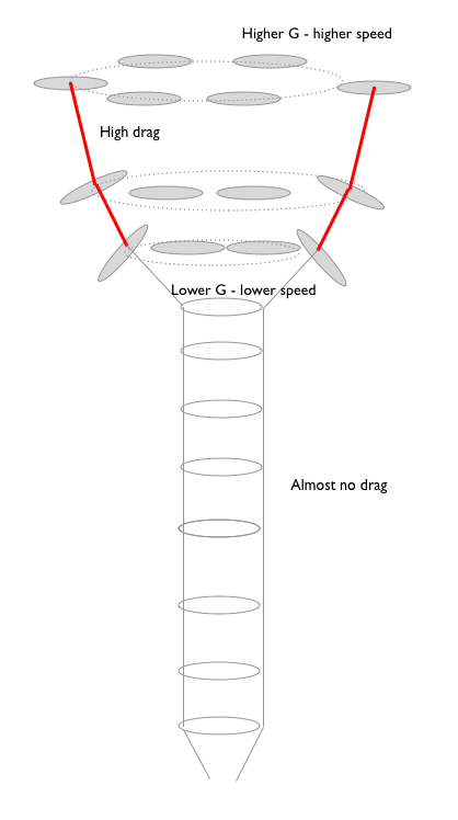
The lower layers would contribute mostly to keeping the mesh with a bigger and bigger radius. The top layers provide the energy.
https://www.wolframcloud.com/objects/tallak-kitemill4/Published/radial_awe_power_v3.nb
Btw: I also think this will be “interesting” to launch in 14 m/s wind, and even more interesting to take down in 25 m/s. Handling one kite is already a mouthful. But I guess this will be a nice challenge for you guys to solve, no doubt you’ll find a way,
1 Like
@PierreB The expansion of a Daisy ring is going to be limited by
1 by torque transfer geometry … if you increase radius you likely also want to increase spacing to the next ring down. you don’t want to crash into the ground, go into the wrong airspace
2 any expansion needs some equipment to release tethers toward to connection points on the network … I suspect this is more problematic on smaller devices as even though you need to hold more line for a larger expansion… line is cheap and strong and the expansion force is programmable enough to be easily matched with controlled release machinery.
3 torque @tallakt nailed it … we don’t want too much for our transmissible capacitance.
4 efficiency why stretch beyond where we are working at our best? Maybe there is a survivability reason I don’t know.
probably other sensible reasons too.
1 Like
Oh the simple elegance of a winch system.^^
I’ve read the thread but have seen only one advantage of torsion transfer to the ground or another ring:
Going crosswind without controlled kites/blades.
This advantage would be negated by your latest design, @Rodread.
Anything I’m not seeing?
Thanks, got it.
As someone who always tries to build castles in the sky, and has learned through experience, this just seems like a distraction. Build something, test something, learn from it, repeat. That’s how I would do it. This is not a problem you can solve just by thinking about it, you need the experience from testing.
If I try to isolate the most important element in your idea, I think it’s the kites? So I would just focus on them for now. Make a few and try to get them to fly in the way that you like, and get them to fail gracefully. Later make them go along a loop between two points, and so on.
I’d like to see a test like this from you some day:

You can measure power in at one end and power out at the other to get an idea of how much power is lost per meter. You can imagine loads of ways to do it. An easy way perhaps is to have one side fixed, the shaft in between, the other end on wheels, and attached to that on the other end a line with a weight hanging from it over a horizontal rod to simulate the tension from the lifter kite.
A very important unknown in your design I think is how much power is lost through the shaft, so testing that is important. More generally, the novel idea in your design is the shaft, so testing that is good.
How long would you like to make the shaft? 50 meters? 100 meters? Testing will allow you to know if that is viable or if the power losses would be too great, or if it would have other problems.
I disagree. The only marketed AWES is KiweeOne. No crosswind kite is close to be marketed, the reason can be the excess of land and space use in regard to the tiny useful swept area for a single unity. It is not possible to prevent secondary uses and aviation in 4 km3 for even 5 MW. It would be a little better within a kite-farm, but not enough. Some solutions are studied like “dancing kites” or rotating devices in order to better fill the space. I built some small POC but prefer going bigger after a deeper analysis of what can work, using also the return of experience. For example some elements from Daisy can be useful for my rotating system, but I do not still know which.
A lot of working prototypes has be made without any commercial success. In my opinion developers are too focused on the machine, losing sight of its environment comprising also the public acceptance.
And some problems are underrated. For example a crosswind kite generates an irregular power due to the place of the kite within the window of flight. Please see for example the FlygenKite I built and shown on Dieppe festival 2012 (https://www.youtube.com/watch?v=RE3GEEDd0AI): both sound and light show an irregular power, involving in a low quality of the produced electricity. Even windmills are now disputed due to their intermittency and the required use of some backup like fossils. So deeper analyses are useful.
[quote=“Windy_Skies, post:56, topic:71”]
If I try to isolate the most important element in your idea, I think it’s the kites?
[/quote] It is the power/land and space use ratio.
1 Like
I discuss again about the bank angle as it provides radial (expansion) forces as mentioned in your chapter 21, allowing to keep the rotor shape.
Supposing that there is only a single ring, please what could be its maximum diameter in the same configuration, by keeping a good behavior without deformations during the flight, using giant flexible wings if possible?
Thanks. You have some good points I think.
I should have said “technical challenge.” But as long as you are formulating hypotheses and finding ways to test them them you’re on the right track I guess. I like to focus more on the enabling technology, here that being the kites and how to control them I think.
1 Like
It can be some passive and active technical features in order to improve drastically the power/land and space use ratio. And these technical features can concern the kite as well as the ground (or aloft) conversion system and the connection of both.
For now the main hypothesis is the viability of AWES, and that is not purely a technical concern.
3 Likes
Nobody under the cable is a bit daft… at AWEC 2013 most everyone stood behind the van… right where the lashback was going to strike if the cable on the drum on top of the van snapped. doh