Networked kites have real and important advantages in efficiency and safety.
Networks are characterised by short sections of line which connect to more than 1 section of line at each end.
Think of a spiders web. Those wee critters don’t want to waste time squirting bodily fluids in an embarrassing manner . Nature learns not to do that. If one thread on a web breaks… force is routed around the hole.
In much the same way. Lines have been observed to break on a working daisy rotor and on the torque tube too …with little to no consequence.
So that’s safer.
Networks break well if they break. (kinda frangible)
Next is efficiency. Short sections of line is key here. Daisy networks (and the OM kite soft rotor network I put on Youtube) use rins of kites stacked in layers. The distance between kites and layers is short. So again we have short sections of line connected to multiple lines at each end… But the advantage here is effieciency in terms of line drag. The torque transfer lines are short for each layer thus little drag per kite area. The lower end lines are on smaller diameter rings thus less motion and less drag per line. On larger systems the lower lines will be stronger thus more efficinet material use where it is needed and only thin lines going through fastest. The lines connecting a kite to the next kite on the same layer have some skin surface drag which isn’t generally as bad.
Launch and land is an essential part of any AWES @Tom
Having lift and generation as 2 separate problems make life easy.
An advantage of using a lift kite is better control over launch and land of your complete AWES.
If line tension is dropping, you can drop a net down a lift line and know it lands in the right spot.
I’ve seen some wild launch and land yo-yo systems but they are definitely improving. Twingtec looks really smooth now. Would be interested to use one of these well-controlled kites designed for yo-yo as a constant force constant length top lifter.
@tallakt thanks again for your working and questioning.
Yes a disproportionately large torsion (twisting) of the network stack will destroy it.
However, this can always be avoided. The torsion is controlled by how much torque is applied to the tube. Zero regen braking current in the generator = zero braking torque applied to the tube. At this point, the only drag on the system is line drag. Since this system has such high line tension and relatively low line drag (characteristic of stacked kite turbines) there is very little torsion on the torque tube line set. The safe amount of torque to be extracted at any given moment can be controlled by monitoring the torsion.
e.g. too much line twist = back off on the regen. Lines too straight up the stack = OK for more regen
As before also the amount of line twist is also determined by the geometry (spacing between radiuses) of each step in the torque “ladder” tube. Also If the rings can handle more compression, we can set for higher acceptable running torsion levels.
Having said that, our initial prototypes have driven safely (until last test) just from looking at generator speed as a proxy for available power.
Thank you very much for posting those Wolfram sheets. I am going to need time to pick through them more carefully to make sure I comprehend and agree. I’d be very grateful for a nomenclature sheet, more commenting, labeling and references to the related formulae if you have time to provide them.
My soft ring kites were low solidity even at that small size, so I fully understand your reluctance to increase diameter.
I agree about the problem of compressing rings near the top of the stack if you have smaller driven rings above them. I currently use a small, solid, not driven ring above the topmost driven ring. just to help lifting at launch and to help maintain alignment with the lift kite line.
As for the system becoming overpowered, … the design is mostly tensile … general rule alert … tensile = incredibly strong / mass so it should be fine… however yes I’m now moving to rigid blades which exploit compressive components. So strict analysis of possible forces is needed in the design stage to ensure no breakaway. Crashing my first flown rigid wing at full speed into the ground (~10m/s wind) demonstrated that the 3d printed (low density) fuselage parts were too fragile. The wings survived fine.
In earlier tests the wings and spars were being centrifuged out of their sockets. Tensile tape and line solutions fixed this.
I have launched in some horrendous winds. There was one test where I saw an anchor fly over my head. That is not allowed to happen anymore.
By the way good work on the drawing. I’m always delighted to see other designs on this method. And there are so few of them.
Oh @Tom
You’re right the most simplistic daisy design may be the best … by employing no control on the wings they are as light & strong & therefore efficient as possible… fabulous … maybe the only control we want is some sort of remote operated outer tether exploding bolt release for any untoward circumstance.
otherwise advantages include but are not limited to…
continuous output = cheaper better
network scalability = cheaper better
safety = cheaper better
simplicity = cheaper better
no line wear = cheaper better
less land use = cheaper better
separated lift and drive = longer operation windows with easier operation = cheaper better
modular design = adaptability = more applicability = cheaper better
efficiency = cheaper better
overall I’d claim (well of course I would) they’re going to be cheaper and better
Want to do a test like this for my own tensegrity torsion transfer.
Not power in-out but just measuring static tension and torsion.
I does not have a center-line.
Thanks @Windy_Skies this is one of the main components of an ongoing PhD by Oliver Tulloch in University of Strathclyde. He published a poster showing results from preliminary research including the test you describe at AWEC2017. We’re working on getting further testing, model development and simulation done.
Please feel free to try too.
Let’s not forget Skysails!
Here is Peter Lynn’s analysis about “Kite Power for Commercial Shipping”: http://www.peterlynnhimself.com/Kite_Power_For_Commercial_Shipping.php.
I just wanted to state that a crosswind system is on market.
I disagree with that analysis on many points. But that’s for another thread and another time.
Hi @PierreB
OK, interesting question, you want to find maximum radius with a single ring…why not?
Well it’s going to depend on where the ring flys from.
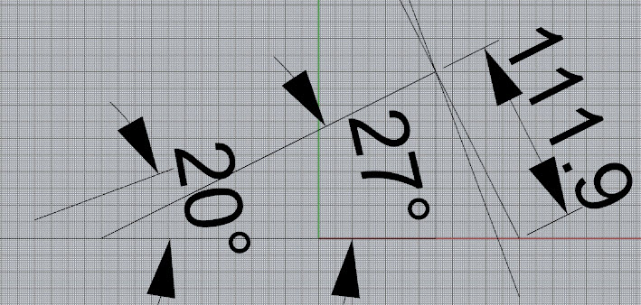
If the ring is flow from the top of a torque tube shaft say 100m above the ground at top and set 27 deg elevation the perpendicular rotor will hit the ground at 111m radius.
Otherwise as you have suggested with rotating reel system you could fly from a large ground ring set on the ground plane and actively keep adjusting the tether lengths as the whole flown ring rotates
As @tallakt was pointing out earlier for a given wing set maximising the flight radius isn’t a route to optimal performace
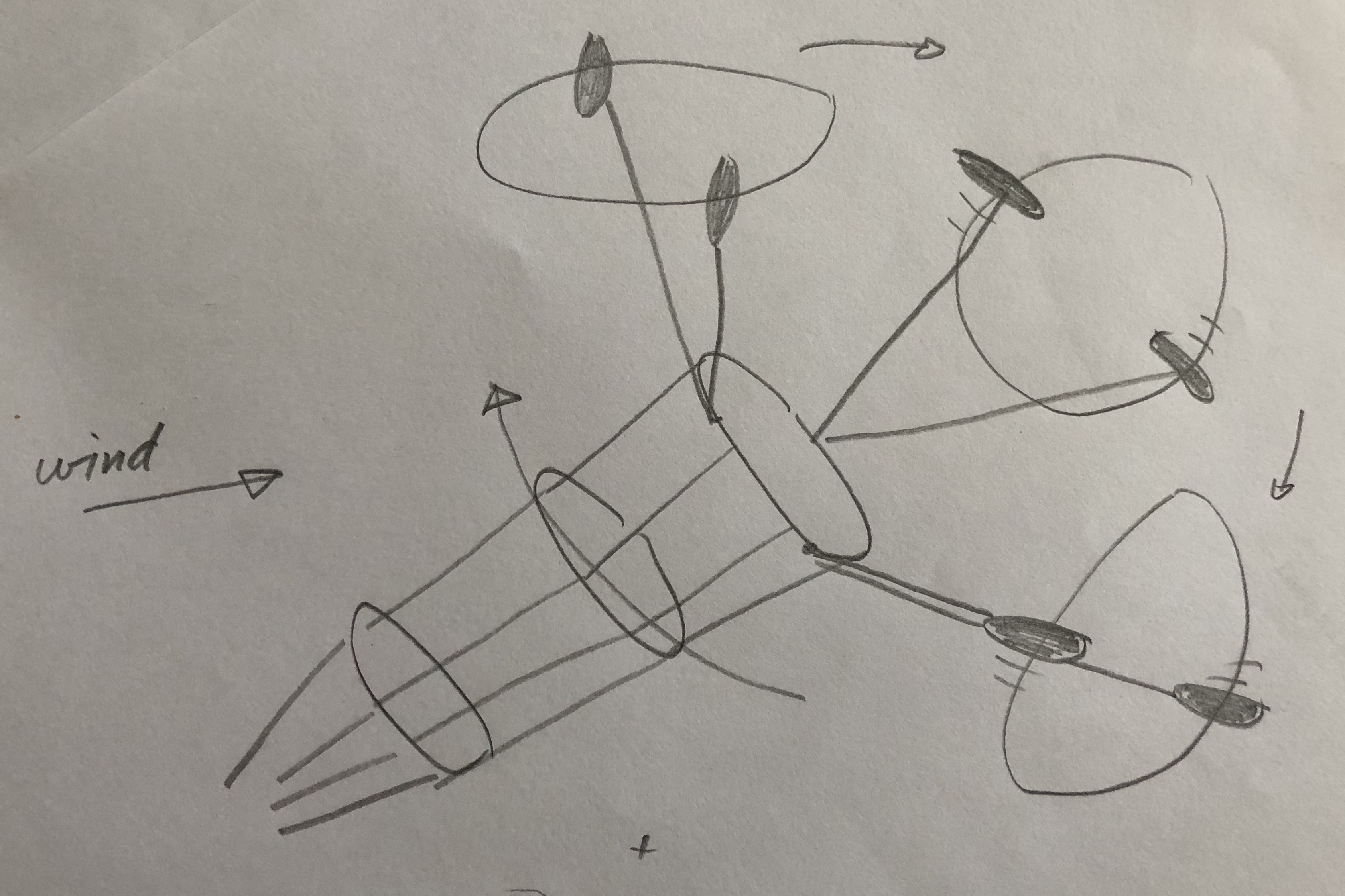
Ok, @rodread. I’ll let go of all practical concerns this once, to make a point.
You want to make kites travel fast to get max power output, and you also want to exploit all your airspace for wind energy harvesting. This could be good it you were approaching the Betz limit.
To harvest power near the shaft line is difficult, this is why this drawing uses three pairs of kites which are again rotating to cover all airspace quite optimally. Only one layer is used because flying in the wake is not good IMHO for many reasons.
This concept works better for Jojo than for Rotational AWE I guess
The wings area would increase while the flight radius increases, keeping the same solidity.
I try to know if by using the bank angle of the kites for the rotor radial expansion, it would be possible to keep a stabilized rotor shape even as the diameter is high, if possible more than 111 m. After all perhaps using the bank angle is already envisaged for “dancing kites” in order to keep a stabilized shape, avoiding collisions between the kites.
If such an arrangement is possible in large scale for one ring, it could be suitable for Rotating Reel, but also for the pumping mode (yo-yo) or with generators aloft, adding also some active control for an automated management of landing and recovery, and a better optimization of the kites making the rotor.
I believe the dancing kites could be flat in the rotating plane for maximum lift along the main tether, if the line length are chosen correctly. I also dont think wind speed necessarily will change this geometry (I havent done the maths though)
Continuous and regular output: a key for the production of high quality electricity.
I agree 1000 times.
Oh that’s a cracking good fun drawing thanks @tallakt ha ha …
but I only ever turn it clockwise
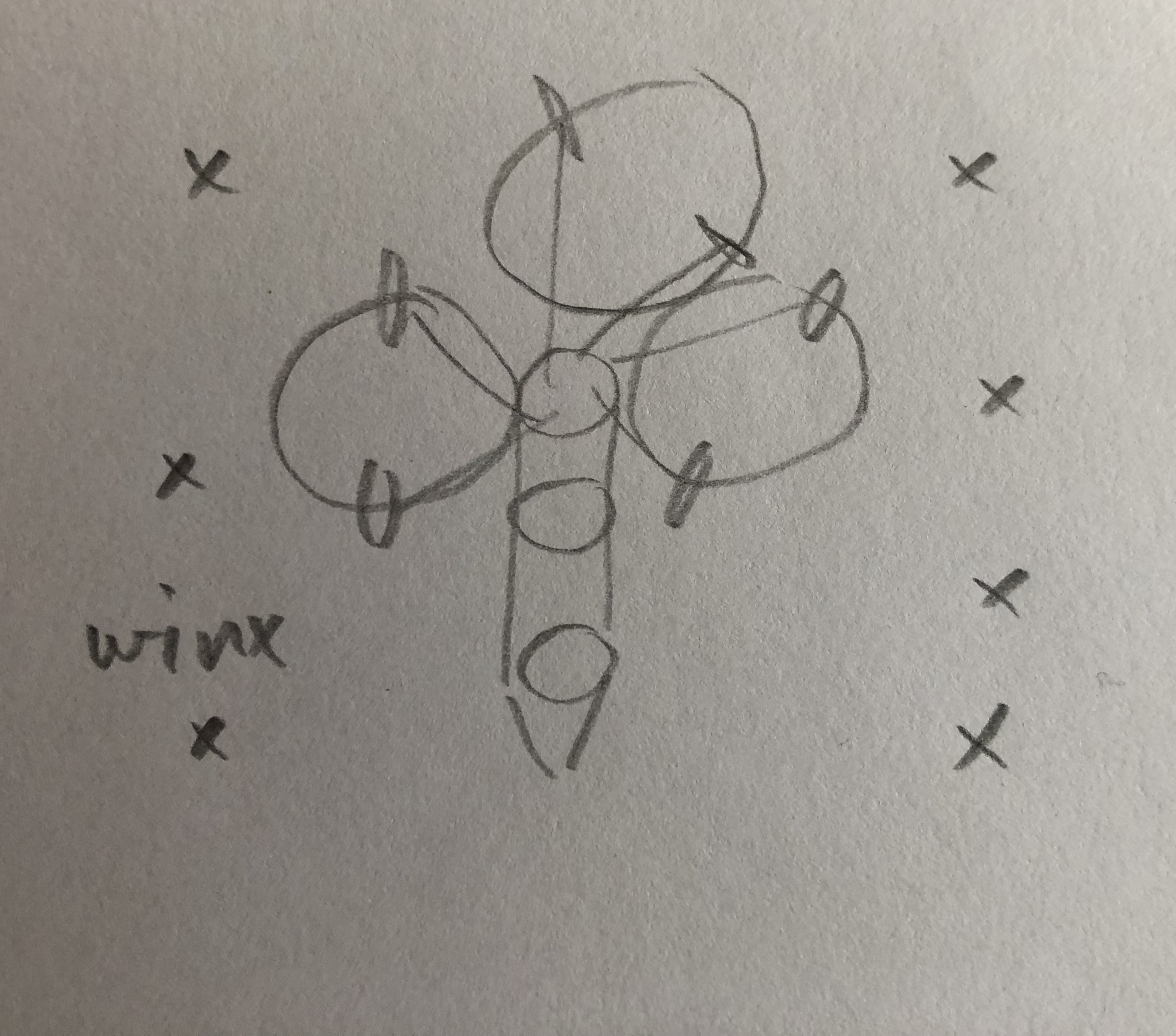
As for how to stick more kite in the sky on a rotor stack… I conceived something I called an OM kite…
it’s basically a Daisy but with more kites side by side or elsewhere between rings.
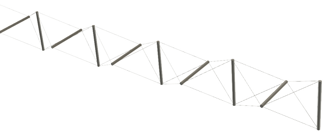
This is an overly simplistic FEA simulation of how it might behave
That’s it modeled as a pure soft form kite network with 168 kites in a 24 per layer (6 positions 4 kites wide) x 7 layers. I suspect This kinda kite would likely benefit from being flown from a nice wide base PTO ring same diameter as the shaft as shown
Increasing wing area is something I had considered by
maybe using a kinda tape measure unwinding tech
or inflating more cells
or unfurling
but it always sounds soooo tricky to implement. I’m sticking to basic cheap and dirty for now till I can be convinced otherwise.
I kinda do fancy a wing made like

As for bank angle. The effect it has on expanding the daisy can be seen as the almost Reuleaux triangle shape taken by the daisy ring in the test videos
Also @Tom, I considered different ways of making a rotating shaft some time ago. I became convinced a rope drive would be better for an airborne HAWT, so I am developing that instead. Superior to that I think are the different ideas that came out of Wubbo Ockels’ first concept, but I don’t feel confident I can make a contribution there.
If I did want to research rotating shafts, I’d try to do something with the “tensairity” concept.
It’s just for fun. Mainly inspired by /cb’s experiments. If I had to develop a useful system I would go for direct traction or jojo/winch.
Btw.: Does anyone know if he’s still actively developing his system?
I redid the Wolfram workbook so its perhaps understandable. I’m sorry the first version was just a sketch, and also wrong. The results are similar though.
https://www.wolframcloud.com/objects/tallak-kitemill4/Published/radial_awe_power_v3_rev3.nb
As tether drag is a non-ignorable factor in AWE, I tend to think that tethers should be as thin as possible. I do not think being overpowered may be taken easily. Even if you let go of all the torque your generator will be fine, but your tether tension will quickly become massive. If you have a low G (L/D) wing, you wont notice much, but once the G values are in the 10+ range, things happen extremely fast and punishes you hard.
Also controlling the AoA is a good way to lose power, as with lower Cl, the speed drops quite quickly as well, giving a lot more depower ability than you might expect.
- Continuous output
Probably not very relevant. Variance due to wind variance exists anyways. Yoyo cycle is not very long. A simple flywheel / transistor / battery could handle that. KPS use two kites to have more continuous power gen. - Network scalability
Yoyo kites can be scaled, adapted, added and subtracted as well. - Safety
Probably correct. However not very relevant. Would use uninhabitet area anyway. - Simplicity.
Only if there is little control. I see rotary as a good way to keep crosswind kites/plites/blades on course without complex controls. Yoyo is were straightforward if it were not for flight control, including launch/land. - No line wear
Not sure if that’s a big factor. Winch is usually only one layer. If designed well there should be little wear. (You will also need bearings for the center line.- Related because of parts moving against each other, transmitting force) - Less land use
Don’t see why. If swept area is the same the land use should be about the same. - separated lift and drive
Don’t see how that’s an advantage. - modular design
Yoyos can be modular as well. Just plant a few smaller ones, use different kites, different generators. - efficiency
[citation needed]
I’m not arguing against rotary for the sake of it. You’re just talking like there are some obvious benefits and I just don’t see them. I want to know the truth whatever it is.