Thinner teather might be heavier (weight, inertia, centrifugal force).
There will be an optimal balance for each system.
Later maybe low drag lines will be developed. Using more of an airfoil shape for non-reeled lines or use the golf ball dimple effect.
Rope loop driving with a kite involves continuous loop flying and if we take advantage of small loops at speed, eventually, small loop output becomes rotary like a shaft.
Small loop advantages include easy deployment of smaller equipment.
Small loop flying may also allow you to exploit inefficiencies in wake effect flight, to reduce overpower.
Small loops can be enlarged later for more swept area and power as needed.
Concentrated shaft power is how we normally extract power. Concentrating kite power to match this, means fewer steps to process, for efficiency sake, in energy conversion.
Small loops can be driven by long shafts of kite rotors for HEAPS of power.
I make no excuse for the potential of this needing loads of control systems but this is a HUGE power design.
1 Like
Can you clarify what you mean please?
Naturally one does not make lines thicker than needed. To make them thinner one would choose another material. Materials are more or less distinct.
For example one could have very thin lines if one used steel wire with smooth strands. This results in a weight penalty.
A simplistic energy conversion viewpoint, may say, focusing wind field pressure, to the tip of the generator shaft, is key to 1 step efficiency.
It seems Spectra/Dyneema/UHWMPE rope is the only option for AWE at this point, being approximately as strong as steel for the same diameter and a lot more lightweight.
The next hope might be carbon nanotubes as tether, but that wont happen overnight. Or maybe something will show up in the meantime between these.
1 Like
Well, FWIW, I disagree with this.
I’ll recommend reading Storm Dunker again
I know.^^ It seems very important to you that rotary doesn’t get left out of the conversation. Now is the chance to elaborate on its advantages. They seem to be non-obvious. No larger commercial project uses rotary. That is evidence against it. So if you think they are wrong you will need to argue your point to get more recognition for rotary - also by investors.
1 Like
@Tom I avoid chasing investors.
I prefer organic growth.
My big total $1pcm current investment plan (Apart from my wife of course. Thanks KB) will hopefully grow.
I prefer meaningful work.
If anyone wants to offer help (let’s call it investment) I’m here
obviously
BTW rotary is not a fancy word it ain’t special.
“larger” commercial projects use “rotary” for AWES, rotary flight for tension in yo-yo, rotary flight for drag e.g. Makani type, rotary track for carousel. Everything converts to rotary for electric gen. Who doesn’t use “rotary”? more to the point.
Thanks, but I don’t think I need argument training. Dave S offers that.
Is rotary motion acceptable in this Crosswind kites topic?
Rotary wasn’t a good word. Will make a thread in the forum feedback category some time so that we can vote on terminology. This is also useful when searching for stuff.
Of course. I don’t think there is any pure drag or lift kite awes being developed or talked about.
(Original laddermill maybe but that’s not current)
I didn’t think a lot about rotary (torque transmission) AWE before just recently. It seems the two systems (torque vs tensile tether drag) are more or less equivalent. Where the tensile rig uses 1/3 of the wind speed for reel-out, the rotary rig uses 2/3 of the maximum wing speed to generate a torque.
There seems to be one benefit of the rotary systrm that has not been discussed here yet. For a Kitemill/Makani single wing AWE rig, or even a Y bridle variant like kiteswarm, there must be a turning radius R that, due to the wingspan and mass of the kite, needs to be quite large. For a rotational rig with a tensile mesh structure, this R will be a lot smaller for practical reasons.
The radius R along with the line length L forms an angle (alpha). As tether drag is present, the angle is in practice far from zero. You need a large R for turning, but would rather not have a large L due to drag. For a mesh rig it is easier to have the kites do tighter turns, thus the angle is smaller.
Now, if the AWE rig is to be used on land, the rig will be pointing downwinds and it is apparent that there will be some small cosine loss due to alpha.
But consider the kite being placed on a moving vehicle/vessel to be used for propulsion. You want the force to be pointing forwards or at the very least perpendicular to the path of travel. Most of the time you will want to point the kite high towards zenith (on either side, if zenith is the correct term for this). In this scenario, alpha represents a direct loss of upwind ability.
This is not a small benefit IMHO
Having a look through, your work, I like the concept of simplifying the whole down to 1 kite for analysis.
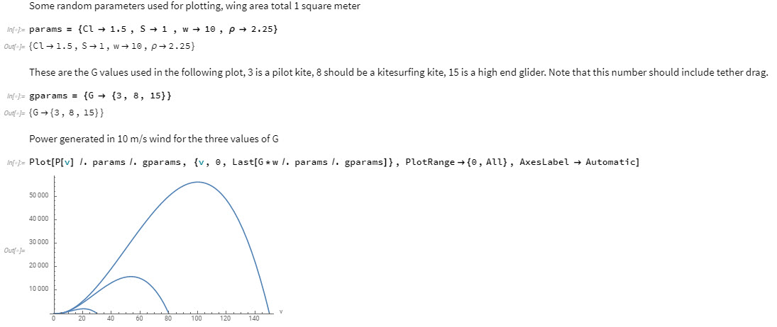
I think the worksheet implies for a given wing where power is extracted from constant length line movement (translation), where the system has a set L/D, in a given wind speed, there is an optimal speed for each kite system to work at. Seems logical and reasonable.
I struggle with not having practiced Wolfram operations, but I’m happy to accept the following as a good model.
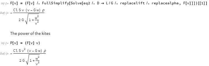
Higher L/D wings perform better.
Perfectly reasonable.
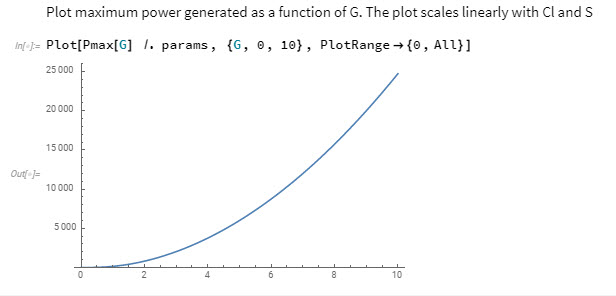
Max Power available goes up exponentially with Glide Ratio again seems reasonable.
Sound like a fair summation?
There will be plenty more to factor in, in terms of wing loading, mass & structural implications…
(Also The air density is @ 2.25 so it may not be representative. Isn’t it usually 1.25?)
Thanks @tallakt
Yep. Air is quite dense here in winter in Norway. The wolfram sheet was a bit quick and dirty. I am doing some stuff on Julia now that simulates the kite for a few loops. It gets more difficult the more you want to optimize it. I dont think I will be able to share the Julia code though as Kitemill probably has ownership
I think adding som elevation and azimuth angle would be some logical refinements, as well as a variable torque output. I also guess adding N wings in a circular mesh could be nice, as speeds even out then. My one kite will go quite slowly upwards if you add mass…
Looks like a rotating awe rig with small diameter tether does seem like a nice setup. I am very curious to see where your project goes
1 Like
For ever finer detail in the models… There’s Uwe’s free-kite-sim work or
IMHO studying both rotating, Y yoyo, Y flygen systems is a purpose of this topic.
1 Like
Initially @tallakt proposed a large version of a TRPT, using spacers like “spars of david”. I think also @Rodread rather envisages a long stack of relatively narrower rotors.
But this topic being about rotating AWE systems in general, other methods like flygen or yoyo or other can also be investigated. As some advantages like an easier control and a lesser space use can be expected we could try to study how such a large rotor could be built then work. Some possible questions are: could a thin ring work at this scale (is the expansion of kites still working)? Or are rigid connections required between the kites? Is there other possibilities?
As long as the inside of the turbine is under pressure then the blades should be able to expand outwardly under pressure
1 Like
Just back from windsurfing on lumpy wind & choppy water in Lerwick harbour - with a lesson.
I got thrown (catapult) quite a few times. Mast too stiff, fin too long, deck plate too far back, wobbly rider, … Who knows really, it could have been a multitude of other factors.
Here’s today’s lessons for rotary AWES from windsurfing.
Rigid wings are faster (Windsurfer is faster than kite for same size sail in same wind) no doubt.
Rigid will spin helluva fast when it’s held at the inside pivot. Catapult is too out of control for a useful system though. Well controlled loops can be thrown by better sailors than me.
I took time rigging & re-rigging to get the best combination of my kit for the day.
I changed down and rigged flat. (Rigidised downhaul tensioned sails can be adapted for wind range… More tension = flatter sail which spills wind… I would love to add a downhaul tensioner mid spar on a kite to pull both ends flatter and spill more wind… not patented)
However, a flying wing can be usefully matched to a broader range of wind, especially top end.
Having windsurfed for ~30 years my understanding of control methods is good and fast but not always fast enough. Who’s to say, for a given situation, if my control actions will be strong enough or fast enough to match the gust, chop, skeg snag, whatever hits…
There’s a “common thread” (pun) here with yachting. A Bermuda rig doesn’t catapult so easily. The mast can’t piviot backward on the deck as the forestay is tied to the prow. Nor forward as the leach tension from the main sheet holds the mast to the stern. That’s a physical restraint which removes a degree of uncertainty, & providing a controllable yacht.
There was no common thread with Makani. This is my gripe with single line kite rotation. Where the flip is the force going to come from to get you inside & back around that loop. Nothing is in the sky wants you to go that way. All those wiggly wee air parts want you the hell outta the way of the power zone.
you’ve got nothing to fight back against that.
The common threads around a multi kite rotor restrain the multiple kite motions to a shared loop. They do it at an actuation speed of up to mach 30 (speed of sound in Dyneema at breaking point)
I doubt even the brains of my hero windsurfers have time to compute a flight trajectory in a loop that tight. Let alone massive twitching strength to control it at a valuable power. Flexing wings and rigid lines do though.
I kept going & the conditions improved… Short , but a good session all in all.