Its unclear whether Pierre means “too much power consumption” simply for the realistic friction load of the prototype’s recoil mechanisms, or power loss inherent to the architecture. The only considerable inherent power loss I see is typical VAWT phase loss of direct upwind and direct downwind rotation phases.
Unlike my pulley system the leashes allow a good transmission whatever the angle of their respective ropes, but the higher tension of the unwound ropes distort the appreciation.
I would need a multi directional pulley system managed by computer and following the angle of the tethers, or controlled electrical winches assuring an equal and constant tension.
The figure 22.18 provides a value of the transferable torque of 1 when the two rotors are close each other, so a maximal value that is equivalent to a value of parallel and aligned rotors. But I am not sure if the motion of the ropes under traction leads to a significant power consumption, or if my material is not adapted enough.
I was likely wrong by thinking some additional significant power would be needed to assure the move of the ropes under tension when the two rotors are close each other. The chapter 22 does not confirm it (https://www.researchgate.net/publication/324135034_Airborne_Wind_Energy_Conversion_Using_a_Rotating_Reel_System):
Pages 564 and 565: “The solution is approximative because the residual transverse forces are causing compensating motions which are not taken into account in the analysis. However, the following results indicate that the effect of the compensating motions is minor and can be neglected.”
Page 566: “This essentially means that the transmission efficiency for the ideal system in steady-state operation is, as expected, 100%.”
Some last tests are correcting my bad feeling, using better fixations for the pulleys.
A physical model conform to basic principles of the rotating reel system would be using multi directional pulleys, or winches with generators in order to assure a constant and equal tension of the ropes that is not possible with leashes.
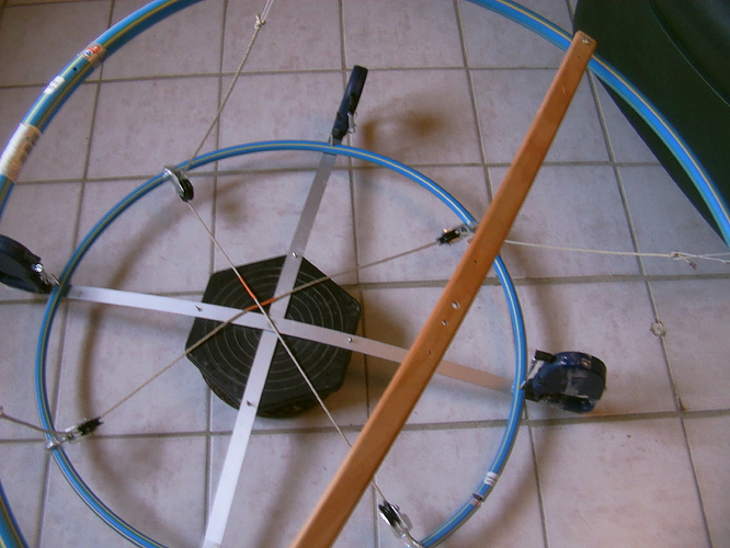
A photo of the pulley system:
A video of the pulley system (see the move of the orange marks):
And also a video of the system with leashes to try to show that a same moment is required to rotate the ground ring when the superior rotor is tilted or when it is parallel and also horizontal, that when the rotors are close enough each other. As in all cases the tension of the ropes opposes a resistance to the rotation, I tried to hold the rotor at the same height (the whole parallel rotor then the top of the tilted rotor) in its two positions in order to make a fair enough comparison.
Now by assuming a good material is used, the forces and moments are unbalanced in such a way that a stable mode of operation would be difficult if not impossible to find. Unbalancing is the big issue of the rotating reel system. I do not know if some aerodynamic or mechanic means could correct this.
Just a dumb question: why cant the generator be mounted on the rotated ring, so that the horizontal ring is not necessary?
By rotated ring… are you meaning the airborne autogyro part?
If so, and it is tethered from only 1 point, (sort of like a spin bol kite) so that the system needs the means to interface a generator to the expanding tethers or to the tensile ring which the kites are mounted on … (There could be many tensile kite rings on a cone form)
In this case, any method is going to drag at the soft line (network or not) so deformation of the turbine and lines is going to happen.
Well maybe you could run a beaded or toothed band (like those beaded curtain reeling control lines) over the top of the tethering and pulled to go round a generator place on the ground, with the band running somewhere between perpendicular to the axis and perpendicular to the effective top of the cone of tethers.
That would be taking power from the top side, Somehow I’d kinda think the best way to avoid compression is to have the generator spread it’s interfacing on the bottom to up-going quarter , from around 6 to 9 o’clock.
So maybe the gen could be a toothed wheel hit round by successive lines
Or the gen is a rail guide holding wheels clamped against an expanded outer ring of soft line… probably best with an outer gen driving band sewn to an inner kite driven band. Sounds kinda hard to do but possible.
