Failsafe, ease of use, simplicity is what we generally want.
How can the PTO help to guarantee we never unload our wings in their fully powered AOA in high winds to avoid overspeed.
If an airborne turbine set is connected directly to spin a waterborne ring.
Can the ring inherently lift water, with channels cut into the ring such that, as it is spun by the kite set, it lifts water… then if the water is used to power a generating hydro turbine… it won’t matter if we have a brake and generator and pitch or other wing breaking controls failure at the same time…
Otherwise … maybe we don’t need to be turning any heavy machinery and dragging it through water, shifting some tight rope rings around on tight frame ring rails will do. That sorta became the intent with the floating cone … The PTO driven ring was on the inside of the floating ring so it didn’t have to run through water.
If we can avoid an unnecessary conversion… efficiency.
I should probably put this in a thread of it’s own about seaborne daisy with anchored tilting cone PTO
Is this AWES work by traction instead of rotation?
Apologies Pierre, I was on about rotating inside the tilted plane face of a floating cone structure.
I should be in another thread probably
The idea with hydrofoils is perhaps good, but the simpler step has already been worked at: https://www.youtube.com/watch?v=9D0JIB6hYc4
Rails should provide similar benefits as a hydrofoil vessel offshore…
With a hydro-turbines-ring (with or without foils) all the parts are rotating.
With a rail-ring like @Massimo’s or NTS’ carousels, a support for the stationary rail-ring is required, involving a rotating part (chariot or train) and a stationary part, and a support to place them above water, leading to a probably more expensive solution.
Concerning onshore installation, see at 1’22’’ the poles sustaining the track allowing passing: it is a huge installation as the rails undergo large tractions of which parasitic forces without the ground protection.
So for offshore installations, IMHO, a hydro-turbines-ring implementation look to be simpler.
And for onshore installations, why not a circular rope (possibly on poles) instead of a rail?
the water viscosity will waste most of the energy harnessed.
It could be the same for https://minesto.com/, however this system seems to work in spite of the relatively high speed (until about 15 m/s) of the hydro-turbine.
Beside it I wonder if a vortex can be generated by the rotating ring, even if only the hydro turbines are in the water thanks to the foils raising the annular structure. If yes I wonder if such a vortex can generate too much drag.
For the water viscosity issue «it depends». For sure someone should do some calculations to determine the probable outcome. But I can say this:
- Kitesurf hydrofoils have very little drag, perceived relative to other vessels
- The foils need not necessarily run at the same diameter as the kites. As drag scales with v^2 a diameter ratio air:subsea of 3:1 for instance would have a dramatic effect
- I dont think in terms of viscosity much, rather lift-to-drag, and I gather wings work mostly the same in air or in water
The sooner fast kite motion becomes fast coils through magnetic fields the better.
Don’t waste material, effort and energy getting this to happen.
Make kite motion and generator motion fit together.
What’s the most efficient transport? A train on rock solid rail, hard wheels and great bearings. Run it in a hoop for constant motion/output.
A spinning train ring moving magnets past coils… That’s a motor / generator.
Bearings. . Rails. . Same-ish thing. Just align with kite motion. 1st bit of job done.
I can agree.
It is an huge installation comprising a support for the stator (far above water for an offshore plant), a stator then the rotor, so a fixed part and a moving part. With hydro-turbines one can eliminate the fixed part.
How will anchoring impact hydrofoil performance?
Low in my opinion, due to a swivel on the single central anchor.
I’m not a good example for hiding opinions … but I’ll wait for the calculation.
The word Single on such a large system scares me.
The swivel friction should be neglected.
Me too. As (single) advantage a single big anchor installation makes less damage in deep sea.
If the single anchor is broken, the hydro-turbines-ring is still floating (for rotating reel, not for Daisy as a part is in the water). They are too heavy to go in the air by kite lift, but the whole plant could be dragged up the coast.
AWES are expected to be far more dangerous as current wind turbines.
I think forget about the svivel at the bottom of the sea. How will all that torque be transmitted to the bottom of the sea without adding too much drag?
My approach would be to use the hydrofoils to generate necessary forces in 3D to run in a ring, then add a «propeller» (generator?) subsea to generate electricity at the foil. Finally concentrate all energy at the center, above sea level.
The anchor still needs to be there. The swivel is above sea level nominally (may submerge if loaded) and a single wire is fastened to the anchor.
After some thinking I would prefer a “classical” carousel as its use can be easier. It can be anchored in several places. @Massimo provides the dimensions and the weight of the stator and the rotor, page 14, on http://www.kitegen.com/pdf/dossierkitegenen.pdf . The dimensions of the carousel are important but in the same time it is used for take-off and landing. The weight looks to be low in regard to the power.
After studying different AWES I return to the Rotating Reel Parotor as, at least for me, this system accumulates positive features for a successful implementation at high scale:
-
It is a stationary device with continuous power.
-
There is no insuperable limit for scaling. The large ring helps the flying rotors to scale by holding it by distant anchored points.
-
The dimensions between the diameter of the ground and the flying rotors and the length of the peripheral ropes are comparable for a good torque transfer, producing harmonious proportions, and allow to achieve a high power/space use ratio. In other carousels the smaller and numerous kites fly at the same altitude compared to the diameter of the ground ring. A single flying rotor is both simpler and more powerful by sweeping the full area.
-
As an example a ground ring (ground generator) of 1000 m diameter can be rotated by a flying rotor of 1400 m outer diameter, 800 m inner diameter, so 1 036 200 m² of swept area, leading to a power about 80 MW with 10 m/s wind speed, a Cp of 0.2 (leading to the possible use of soft wings) and a cosine cubed of 0.65 with an angle of elevation of 30°. Such a rig would use about 4 km² of land by taking account of wind changes, instead of 50 km² for currently envisaged kite-farms of single unities flying in an erratic way, with a risk of entanglement.
-
The horizontal rotor allows scaling in all dimensions.
-
The secondary mode, now analysed as not productive is simplified and allow variations of the length of the peripheral ropes while the tilted flying rotor rotates the horizontal ground rotor.
-
Safe control by multi ropes and complete depower by the central rope.
-
The ground ring is used to spread the kite, then takeoff by rotation by the generator as motor, then landing, all being automatable.
-
There is no rigid parts between the ground and the flying rotors, as there are only ropes. That facilitates both scaling and safety.
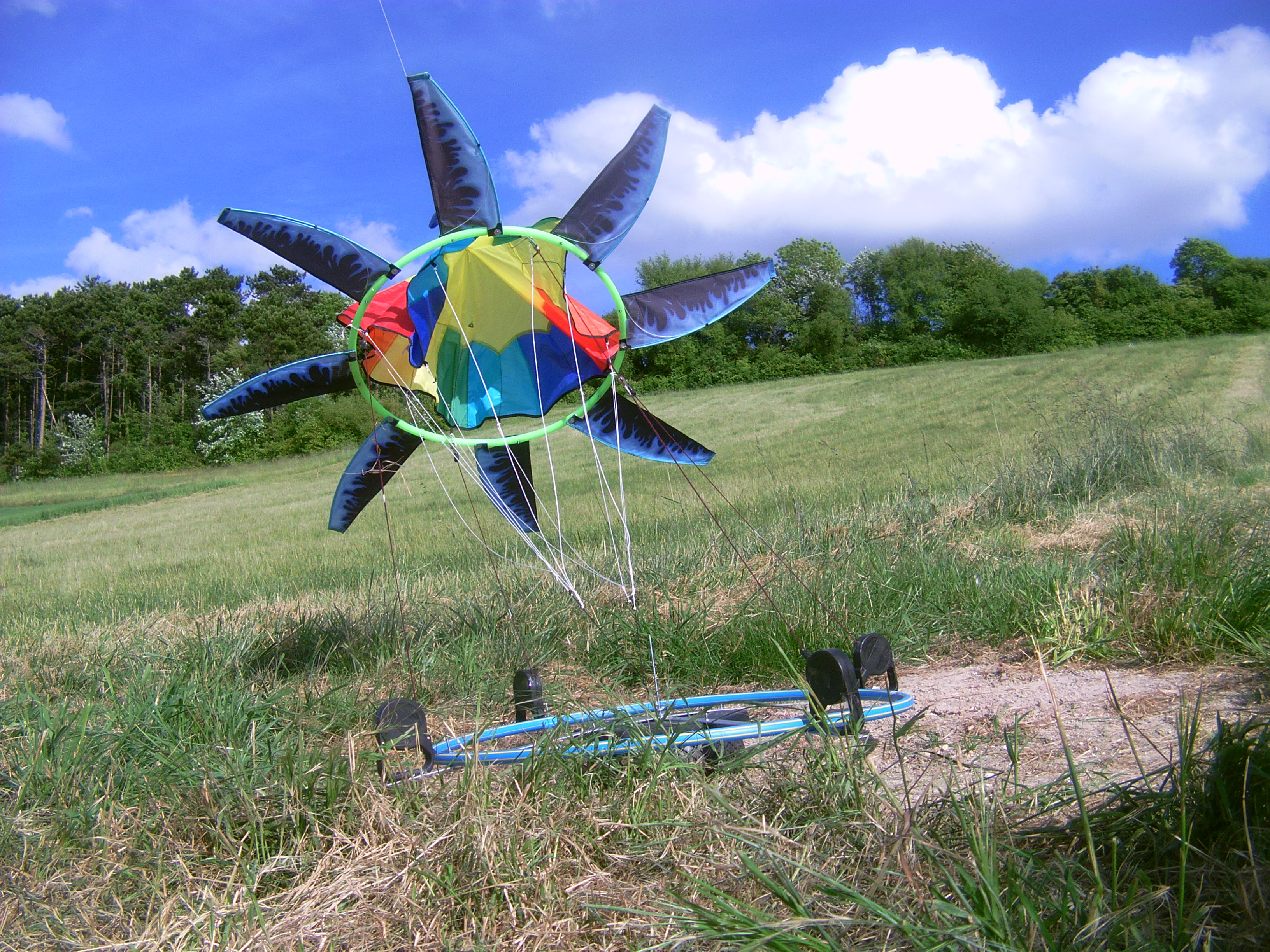
Just to show the principle.
See also the quote on Medium scales for torque transfer systems onshore and offshore - #95 by PierreB.
By using leashes I also noticed the difficulty of the rotation, but I thought it was due to the resistance of the spring when the rope was unwinding. I think a main cause could be the power consumption of the moving tethers under tension. This power is removed from the overall power of the complete system.
https://www.researchgate.net/publication/324135034_Airborne_Wind_Energy_Conversion_Using_a_Rotating_Reel_System : the tension is assumed to be constant and equal for each of the four tethers. When using the direct mode of generation (22.3.2), the main generation is assured by the horizontal ring. Then “The modules are electrically interconnected such that the generated and consumed energy is balanced”, but the generated energy is removed from the overall power of the main generation.
As a result I will study more some other AWE systems.
I would like to thank everyone who participated in this topic. My latest tests and further analysis have shown that there is too much power consumption of the rotating reel system.
But the chapter 22 mentions in the page 566: “This essentially means that the transmission efficiency for the ideal system in steady-state operation is, as expected, 100%.” and in the pages 564 and 565: “The solution is approximative because the residual transverse forces are causing compensating motions which are not taken into account in the analysis. However, the following results indicate that the effect of the compensating motions is minor and can be neglected.”
The “too much power consumption” can be wrong as a 100% transmission efficiency is theoretically possible, and as the physical model is not respected by using leashes (different forces during winding and unwinding) or by using pulleys (forces theoretically equal and constant if the pulleys are well oriented during the operation, but it is not the case). There are also frictions.
The idea was to implement a horizontal conversion system to facilitate scaling and take-off and landing operations.
Nevertheless for the first time a (small) horizontal carousel was rotated by a kite.
How big of you to share even your disappointments. The video is very nice. For a test, I would redo it with the pulleys being more flexible. Perhaps a chain of the links between the ground and pulley. This would make the geometry better when the elevation angle is reduced and the pulleys need to rotate.
I still think the center line is not a good idea, because it it the tension of the outer lines which is the carrier of power.
Seems a few modifications could yield significant improvement
