Remember that it’s using a kite to fly the generator. You have the rotating mass of the stator ring in combination with the falling mass of the ball bearings/ magnetic fluid. It is using wind to turn but also using gravitational potential/ Kinetic energy. Hence its hybrid nature.
1 Like
The Bacteria That Make Perfect, Tiny Magnets - YouTube Should give you some idea what the magnetic fluid could be made of. Tiny magnetite particles.
Ok guys did a little maths base on the lenz law experiment. extrapolate to the generator.
We have a ring OD 0.82m. working off terminal velocity of 9.8m/s2 I calculated the tube length in the experiment is .49m approximately from the time it took to fall. Then did a differential calculation to find out how much inductive resistance slowed the ball > 0.12250014 m/s. which gave it 79.990858-1 reduction in speed while falling through standing tube.
So going from 9.8m/s2 > 0.12250014m/s so theoretically. It would be possible to hold multiple magnets in place with a spinning kite with the generator attached. I believe there would be resonate harmonics in relationship with the spin of the kite. also an infinite fall for the ball/ fluid to take. I don’t want to say perpetual gravity generator. if an objects falling with no chance of stopping it certain would come close. It dose however rely on the fact the generators airborne and spinning. For the example shown.
The total track length is 2.5761038m based on the OD. From standing it would take 21.0293947419s for the magnetic elements to theoretically completely a lap. That would increase due to m/s of the kite spinning as it would take longer to complete said lap if the tube was completely copper.
So recommend coil distance and size in my case it’s 1.4mm wire we have two layer giving it a total thickness of 2.8mm approx wound to 50mm in length. Meaning it takes 0.612507s to pass through each coil if standing. I suspect the voltage would increase the faster the kite spins in accordance with lenz’s law. The ball slows >9.187493m/s through each coil. I suspect this would be different depending on coil arrangements. Be that radial or liner flux. Cored or uncored. So based on the lenz law experiment I can conclude that the magnetic elements will recover if the coil spacing are far enough apart.
For our case the spacing would be 24.150955mm approximately between each coil on centres. This is based of the differential loss of velocity vs coil length. along the total track length. This also give you the maximum coil on each ring 10.666675 coil sets per ring. So I’d say no more than 10 coils per ring. average out the difference between those coils. For design sakes. Correct me if you feel I’ve missed anything as this is only theroy take from terminal velocity. Minus the resistance forces. If someone could check my maths I’d welcome it.
Just another idea to throw into this mix
Here’s a structure which can take planar feedstock (a fairly complex feedstock though) and be folded into a torus with a rail like component around the exterior.

If applied to the designs in this thread it could provide a more convenient way to pack away or deploy your torus
2 Likes
This looks interesting. I am in the process of completely modifying the initial design, because a rotor turning around a round kite is particularly difficult to achieve, especially with regard to the power take-off (PTO) between the rotor and the kite, and the reliability of the two separated elements (rotor and kite).
I keep in reserve the principle of the structure exposed on the video above.
2 Likes
But here, shear stresses would apply between the blades and the rings (of which the ring carrying the blades), just like for this design (where shear stresses concern also the parts between the Magnus or Sharp rotors within the ring). So this would lead to the requirement of a robust and heavy manufacturing. And since a second counter-rotating rotor would probably be necessary, the mass would quickly become prohibitive.
Such stresses would likely be reduced in a configuration Flettner balloon and VAWT side by side in the first sketch where both diameters are the same, if it can work.
A rotor surrounding a round kite or above all a balloon (sketch below) would be a little like this wind turbine, the balloon replacing the big central hole:

The balloon itself could perhaps be a problem, limiting the wind force on the blades.
Also, about the large annular generator (perhaps unless wheels are used for generators in rim drive style):
I would add that a second counter-rotating rotor would be required, leading to more material, more weight:

To summarize, to say that the solutions presented by myself on this topic are unlikely is an understatement.
I remember I had experimented a rotor arrangement including two opposite kites separated by a parachute so that they have a little more swept area.
If I remember correctly, there was a swivel between the rotor and the small kite lifter, and another swivel between the rotor and the main tether. The last swivel was practically ineffective.
Otherwise, this rotor had good traction, but I prefer a parachute of the same diameter as the diameter of the area swept by the rotor in question, because it offers better traction for the same area use.
185 m if a central bol kite of 65 m in diameter is used as a rotating annular parachute.
In this topic two arrangements were described, including in the initial comment, where the video and the photos are about a rotating set (including the central parachute or bol kite) which could perhaps be used in yo-yo mode for lack of a better option. The swivel of this bol kite can be better than the swivel I used. The 185 m and 150 m span rotors are of this type of arrangement.
The second option (with sketches but no more) describes wings or blades rotating around a fixed round parachute kite, in rope-drive or flygen modes, in a very complex arrangement.
1 Like
About the sketch with rope-drive system: after a more in-depth analysis, it seems that this is inapplicable, whether for two counter-rotating rotors (the rotation is canceled, unless only one of the two rotors drives one of the pulleys from above, which has the effect of a lock as soon as the rotation speeds of the respective rotors are not matched) or for a single rotor (whose blades could not have the suspension lines that are nevertheless essential).
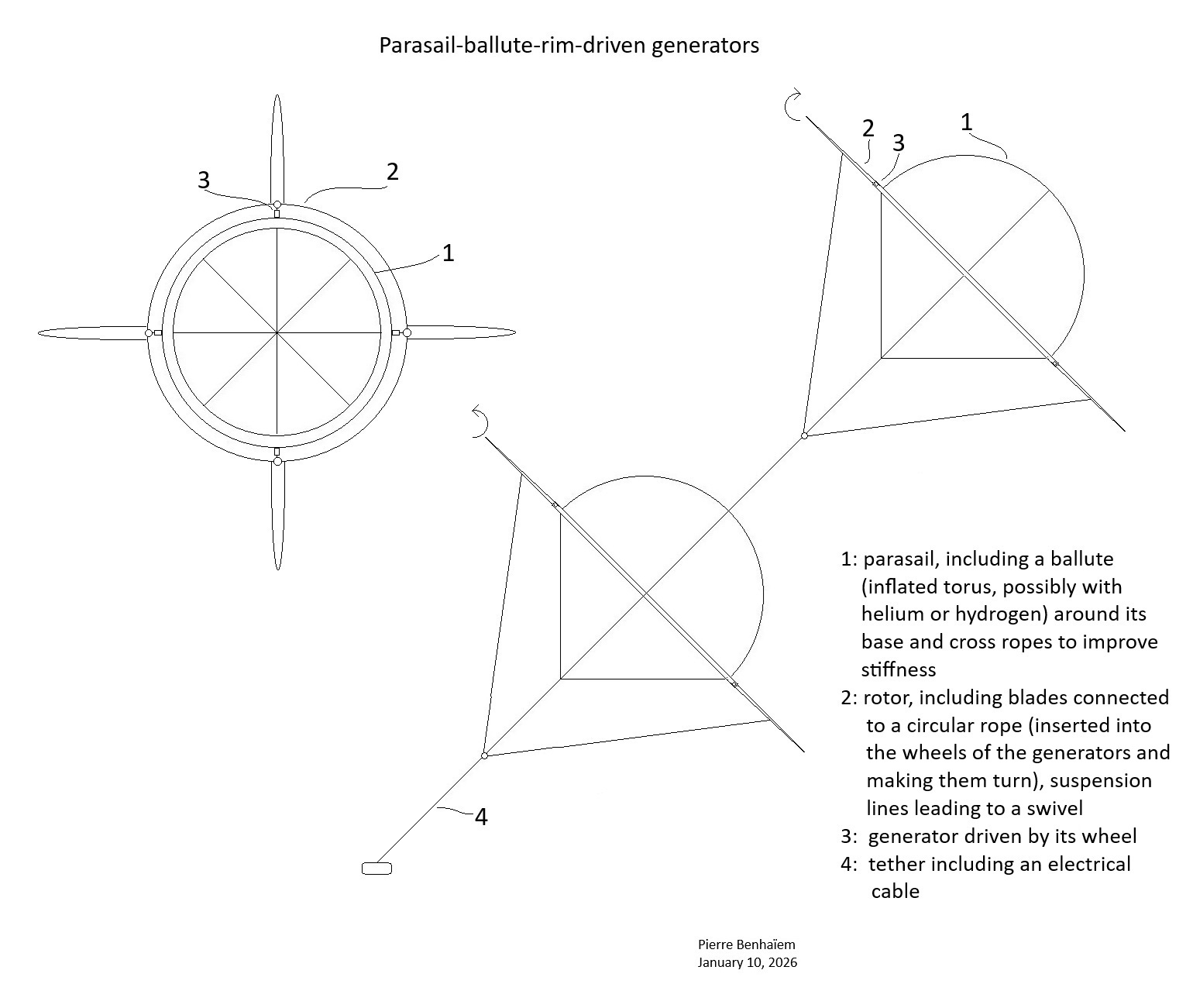
About the sketch with generators and their respective wheels, a variant is proposed below, including a ballute with cross ropes at the base of the parasail, and suspension lines for the blades. There is little chance that this could be effective: at least we can save the mass of the gearboxes thanks to the high rpm by direct drive, using standard generators.