I guess this can be a way to manage the ball bearings in the ring as they pass under the coils by falling. Indeed by the way they slow down by Lenz’s Law as shown on the video below:
My first impression: this concept is interesting and could be studied, and perhaps applied to rotary AWES, but also crosswind and dancing kites like Kiteswarms AWES and flying in circular path.
Just a few things to take into account. I’m not so hot on the maths front. I know how to apply principles I see, to a task. Couple that with a broad range of interest. You have lots of potential to apply plenty of physics to design. Lens law applies to motor, maglevs and other similar designs.
What Is A Rotating Detonation Engine - And Why Are They Better Than Regular Engines - YouTube
I’m not concern about the rocket part. Just how fluid moves in the tubing if closed off. Would I be right in thinking it has a similar wave front? Perhaps even multiple wave fronts? Like a Chlandi plate being example of this. I’m wondering if rpms would influence the wave front? The faster a kite spins the more chance of emerging wave fronts with higher magnetic density. would be my prediction. Also Introducing the FlowRider® Edge - YouTube
More visuals. the waves are the generator the person the magnetic elements. Be that the fluid or ball bearings.
From the author: “In this video I experiment with Lenz’s Law And Faraday’s Law of Induction to generate electricity and magnetic force fields in copper.”
Interesting part from about 2:00 or how a magnet falling freely in a plastic tube is slowed down by the passage of the copper coil when ties of copper are connected.
That was cool. I’ve been doing some sums and If I’m right it would make for an awesome generator. For each coil 50mm long 2.8+2.8 = 5.6 mm thick winding. With od 25.6 r= 12.8 Calculating resistance values per coil if using copper 1.68*e-8(0.05/.51471811m2) =1.63196123e-9 ohms
From this we can calculate the amps due to coil length. when the numbers are punched in. we get 5.8159805amps from a standing coil. Once the voltage and watts are accounted for you get a generator with 9.49145407V and total watts per coil of 55.2021118W with a little more math all 10 coils will give you 94.915407v 552.021118W for the whole generator. Obviously this would multiple in accordance with lens’s law due to rpms. This follows on from my last comment I’ve pasted it in for reference.
Just in case nobody saw:
We have a ring OD 0.82m. working off terminal velocity of 9.8m/s2 I calculated the tube length in the experiment is .49m approximately from the time it took to fall. Then did a differential calculation to find out how much inductive resistance slowed the ball > 0.12250014 m/s. which gave it 79.990858-1 reduction in speed while falling through standing tube.
So going from 9.8m/s2 > 0.12250014m/s so theoretically. It would be possible to hold multiple magnets in place with a spinning kite with the generator attached. I believe there would be resonate harmonics in relationship with the spin of the kite. also an infinite fall for the ball/ fluid to take. I don’t want to say perpetual gravity generator. if an objects falling with no chance of stopping it certain would come close. It dose however rely on the fact the generators airborne and spinning. For the example shown.
The total track length is 2.5761038m based on the OD. From standing it would take 21.0293947419s for the magnetic elements to theoretically completely a lap. That would increase due to m/s of the kite spinning as it would take longer to complete said lap if the tube was completely copper.
So recommend coil distance and size in my case it’s 1.4mm wire we have two layer giving it a total thickness of 2.8mm approx wound to 50mm in length. Meaning it takes 0.612507s to pass through each coil if standing. I suspect the voltage would increase the faster the kite spins in accordance with lenz’s law. The ball slows >9.187493m/s through each coil. I suspect this would be different depending on coil arrangements. Be that radial or linear flux. Cored or uncored. So based on the lenz law experiment I can conclude that the magnetic elements will recover if the coil spacing are far enough apart.
For our case the spacing would be 24.150955mm approximately between each coil on centres. This is based of the differential loss of velocity vs coil length. along the total track length. This also give you the maximum coil on each ring 10.666675 coil sets per ring. So I’d say no more than 10 coils per ring every 36 degrees. average out the difference between those coils. For design sakes. as this is only theroy taken from terminal velocity. Minus the resistance.
I had an idea it would have worked based on what I knew about motor. A very interesting video indeed. I’m just a little surprised nobody has thought to using a constantly falling magnet in a tube? to power something big. I almost want to name It draupnir after Odin. It was the secret to the aesir’s wealth. Every eight nights, eight gold ring fell from draupnir as he shook it. I’d imagine the ware would be very minimal. Spacing would be key to it successfully operating.
I did notice how quickly it regained terminal velocity once it passes through. It is effectively a solenoid at that point. Provided there constantly and rapid interaction with the coils. I see no reason why it would work indefinitely. The harder the coil are hit the high the voltage out. Depending how big the generator ring and track length are? Terra-watts might be possible. Prehaps even more?
Considering the nesting and stacking options. 550w is mostly what appliance need to operate. Mains uk is 240-250v. This may seem daft but 2.5263158 rpm is all you need for that. Based on 95v. So I suspect it would be higher voltages are achievable in higher wind speeds. Perhaps for example you have 20rpm 95v for a moving ring if I got me maths right 1900v. a bit dream world but. It definitely has potential if true? Might even be very efficient? 70-80% would be good nice. Considering it’s friction less potential.
Great demonstration video. Next question is operating temperatures? If heating is likely?
Next question (First) for me is mass
and
Friction-less… don’t think so. Notice the acrylic sheet bend when the magnet drops past… That’s the 2 magnetic fields repelling each other and taking momentum from the falling magnetic mass. That physical force has to be matched at the coils. e.g. in your model the ring has a pulsing retardation with the pass of every magnet mass past a coil.
All of this only happens inside the side of a rotor where the blades are moving upward, that also happens to be the side moving into the wind more.
It’s interesting, but you need to know how scalable the mass of the magnets and coils is.
In the classic sense of the understanding of frictionless is it not touching the side wall when it meets resistance. It levitating. Resistance is not friction per say. Yes there’s a braking force. Equal to the magnets fall. I can see
foresee a scenario where the magnetics trap the magnet In The coils. allowing for rapid oscillating which I don’t think is a bad thing. I don’t know if you had figured out? that the rig bent in proportion to the force acting upon it. I don’t think mass is the singularly most important thing. It the strength of you magnets as there will be an optimum ratio. The thing is you can have a low mass high magnetic field or a high mass low magnetic field. It is how it interacts with the coils that counts. Resistance and distance as well as coil size. Eg if you have coils ranging from 10mm 20mm 30mm 40mm 50mm in length?
It would stand to reason that the largest coil the greater retardant force? will happen in the coils with a length of 50mm. Its should scale with regard to that. Rather than how massive an object is. I was toying with button magnets and a copper tube yesterday. 22mm pipe* 16inches. with 18mm ferrite button magnets with a thickness of 5mm From what I found out with that test is for each magnet I added the resistance increase. It took .31s for a button magnets to fall through the tube. With 12 magnetic in the tube it increased .52s mass wouldn’t be relevant as the levitation force will come into play. As seen in the video. It’s the resistance and how much the magnet can penetrate at speed. In the demo of
It show a possible outcome for this if it spinning. In fact if you can trap a ball bearings between two coils and allow it to move back and forth between them as it spins not only will it make power on the upstroke it’s like to make power on the downstroke as well.
Isn’t that what it’s all about? Taking the science as the benchmark and figuring out if I have A. how will I get to B? I think might be like a leaky tap. It also chaotic pendulum.if you think about it? I know the voltage could be levelled out with a capacitor. Much like filling a bath tub. The simple answer would be to figure out resistive force and the working out the breakthrough limits. As Mentioned it would release on the distance between coils. Should be fairly simple. Gravitational generator…stl (1.0 MB)
(1.0 MB) another Tinkercad effort. Demonstration of coils spacing. I’m still roughing out the design and getting use to Tinkercad. I hope this shows coil spacing stretch out when using the odd one out principal. galileo used in his bell experiment. To measure gravity.
Component is based on 10+50+40+50+90+50+160+50+250+50+360+50+490+50+640mm around the circumstances. there is enough room for eight coils. According to this pattern. With a gap before the next lap. I had wonder if doing it by degrees would have been any better? Appreciate any input @PierreB@Rodread. Thoughts ect.
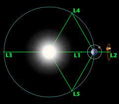
I remember watching this and it reminded me of the bell experiment oh how close a bell must be to chime evenly. With a tweet or two it might be possible to take the whole track length sub divid and account for the the losses. I can’t quiet recall if it was the goldern ratio or fibinacci but a motor/ generator design based on this would negate any resistance and losses. as it will be at a constant. Maintaining the 9.8ms/s as it hits each coil. recovery is key. Toaist might love this because it form the same symbol they use. I had even be thinking of using legrange points in the design as part of coil arrangement pure because it mimics nature. Simple put each time the mass it inducing current in the coil it like the bell in galileo experiment. Early day in the design phase exploring possibilities. So yeah load of fun.
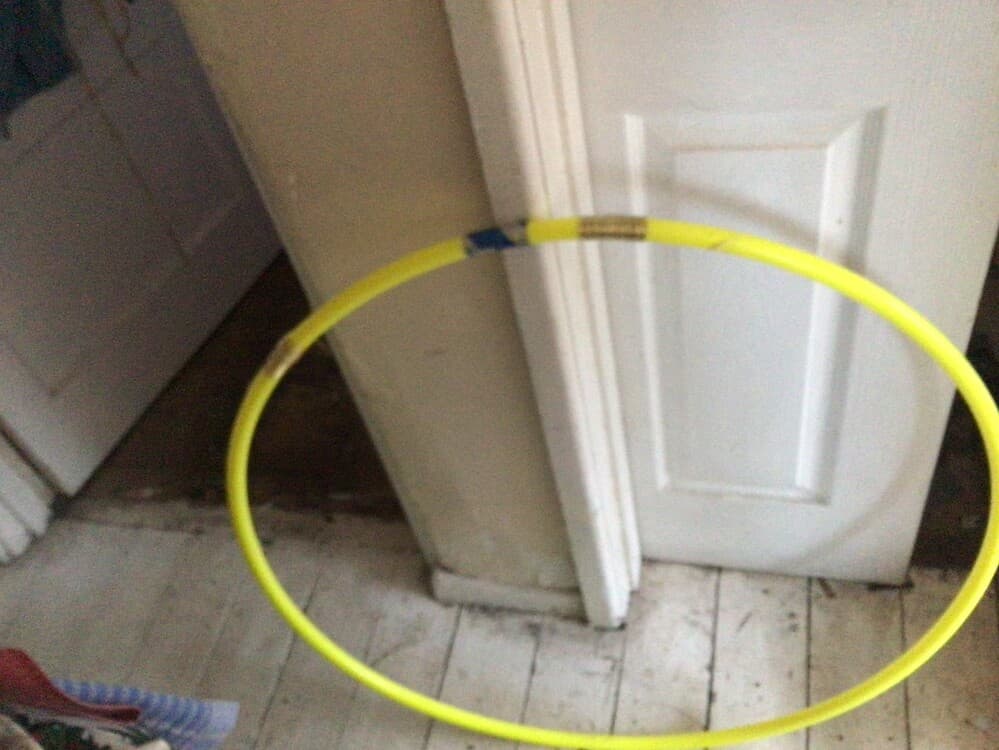
I was sat thinking how it could be tested before rigging it to a kite? Then it occurred to me while searching YouTube. when this gym wheel popped into my feed. Not only does it demonstrate likely situations that could happen. But would give you means to test it. Even for the smaller version taking a leaf out of the rolling hoop with sticks. Thant many, many kids used to play with. An even simpler rig could be set up between rollers.
Was out doing me rounds on the YouTube and this popped up.
I know I’d seen examples. couldn’t remember where? I’m just glad to find this one. He’s European but that’s as much as I can say. This is about 4 year old. He’s lighting a few LEDs. I’d seen example of running charger for mobiles. using this principle. Just out of luck wading through YouTube. To the mobile charger version. Just excited to find this one.
The followed up with.
I seam to be dreaming of an airborne cyclotron
It seems at high rpms. it encounters high vibration and high occultation. which could destabilise it in flight. Much how a mass shifts in a cargo plane cause stability issue in flight.
If rotating in a straight pipe. High centrifugal forces acting on the mass in reciprocal motion. Will result in mass locking above a certain rpm. As the mass won’t be able to return the full length tube. Much like a wushu chain whip
Best way I can explain is a sound tube. held at one end and then flicked.
However? might still be good on a yo-yo looping kites. through the peaks and troughs. Due to the return angles between high peak and troughs. It definitely good for low rpm applications where the mass has a chance to return. I highly suspect a cutoffs with the application due to rpms.
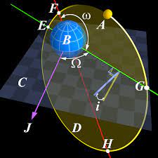
Mass locking is where any mass in motion reaches a point of no return, or reaches a point of synchronised rotation. In an orbit plane.
Two way this can play out In AWEs is? mass become trapped at one end of the pipe and is unable to return. The others is it get trapped along its length in a le grange point. Depending orbital harmonics. This will determine where in the tube that happens. This assume the airflow of the wind remains steady and constant. the returning mass has chance to complete a full trip.
Much like cricketer going between bails. If there not quick they be stopped and stumped out.
This will be it total stroke length
The force of gravity acting upon the mass it at 9.8m/s/s
The time it takes to turn 180’ round the centre of rotation.
It is the relation between the falling mass and the rotor that will determine where the mass becomes locked.
As for a ring verities occultation will occur due to angular momentum. if, rotation of the mass in motion. doesn’t reach a harmonic equilibrium. Much how the occultation harmonic destroy bridges. A very important safety point to raise. Considering tethers and connecting points can be weakened due to stress. Suddenly line brakes can be lethal. if you anywhere in the strike zone. Then a shifting mass could stress a line to braking point.
Important design considering is the size of the shifting mass, kg
The velocity at which It travels m/s
The stress that will be take up in the lines.
The tension of any supporting lines, cables and Ankers while in operation. In N/kg.
Simply put its the torsion length between slack lines and taught. you going to have to watch out for.
If point a is slack and point b. is overly taught. Been given some thought the last few days after seeing the mk2 cyclotron. It might be possible to have it rotate around a Barrycentre.
It still could be stable enough to use. Much like the earth and moon do.though I would have to upgrade my maths to figure that out.
Just something to consider
I would say a great design so far!
Time to work out how to put it to best use.
I think you describe the possible problems for the device I sketched.
Indeed a low rpm is required, so it can work with a huge rotary kite. By the same a huge wind turbine is required for the storage by gravity to compress air.
Moreover I think the installation would be too heavy for an AWES.
At that scale sure thing. However? if a small enough bore and light enough. definitely it would become applicable for awes. Especially if using magnetic steel shot? To achieve the required outcomes.
Build it into a wing structure and use the tube as support braces. Much how the flat pack tents do. There is a lizard the can fly by spreading its rib cage . This would be no different. Carbon fibre or even hemp fibre micarda tubes would do the job. Added bonus treated hemp is fireproof. 100% renewables resource if well taken care of. Hemp matts would be a good place to start. Especially because they can be felted, dyed and made to fit. I suspect the target wall thickness would be 2mm. though could be thinner. Depending on the weave density. This is Just to keep the weight down. It a very good source cellulose. Better than wood if I recall correctly. Cellulose being biodegradable. and is found in eco plastic packaging.
In fact most of the kite could be made from cellulose sheets. if done right?
Pierre: Last time I calculated the G forces at the tip of a super-large wind turbine blade at full speed, it was on the order of something like 20 G’s. I was imagining what might happen to someone stuck inside a blade actually. Wow, you don’t want to be that person! I’m thinking these balls would be stuck at the blade tips by centrifugal force, unable to travel the length of the tube.
At least from what I’ve seen so far, I do not believe falling weights will pan out as a good way to generate electricity in AWE, since adding weight of any kind would seem generally not desirable.
The wider the rotary AWES, the lower the rpm, the less centrifugal force. I mentioned it in my previous message.
On my sketch I thought on a 100 m diameter soft rotor, tangential speed being about 25 m/s. G = 1.27. By the same Seamus Garvey envisaged a 300 m diameter rotor.
Although such a generator doesn’t look promising, I tried to take a closer look: already we have a problem of too high mass. In addition, heavy moving masses interfere with the rotation.
It could at best become an educational toy provided it spins slowly.


")