The scalability of the rotary AWES can be achieved by moving the blades or wings away from each other, increasing the swept area. Daisy is an example where the central part is hollowed out and ring-shaped.
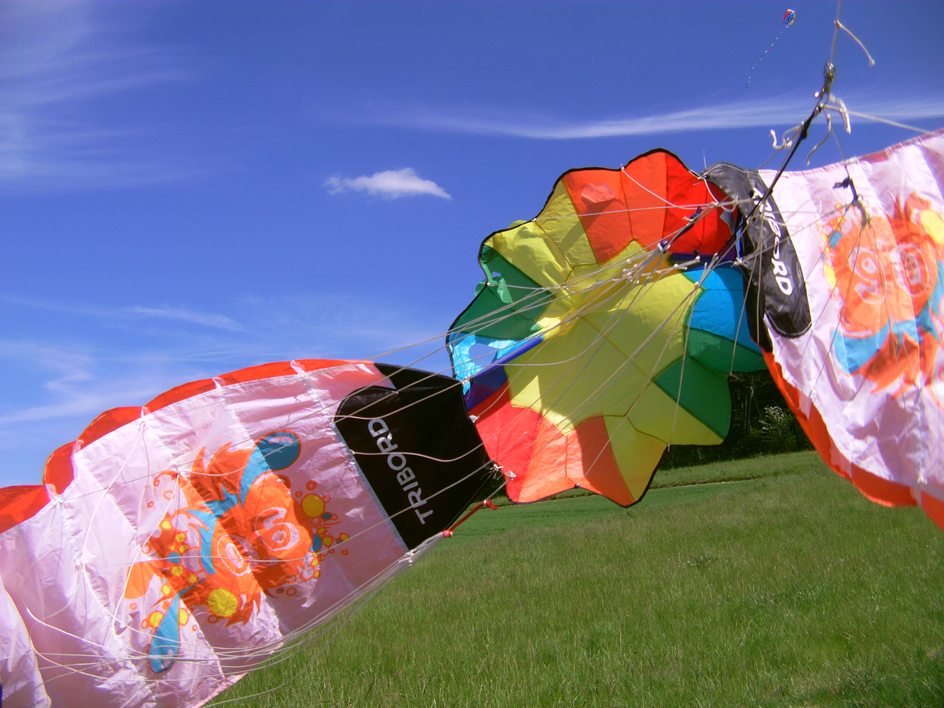
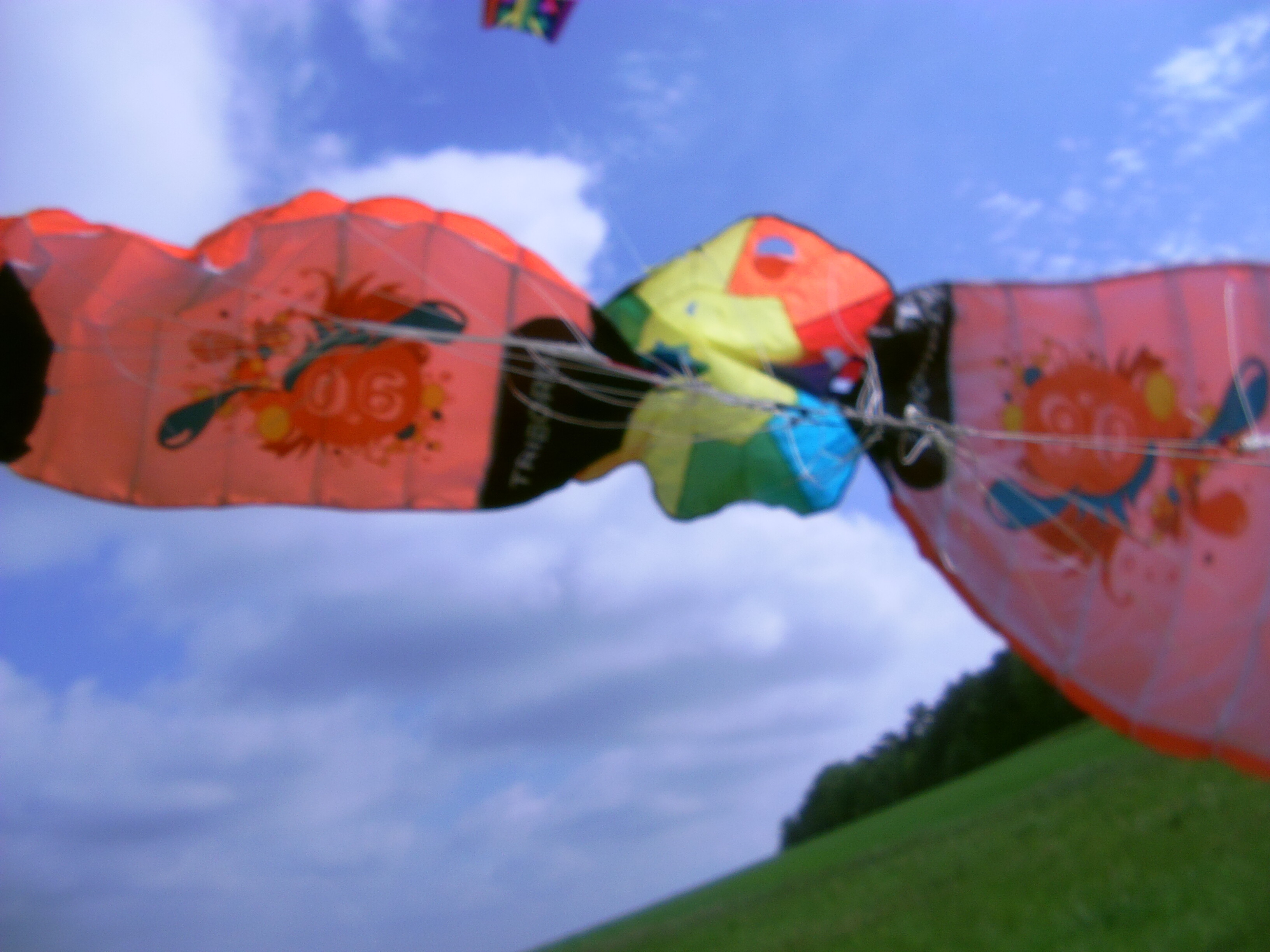
Another example, this time with a central parachute, but rotating with the blades like Daisy’s ring, is shown below. Intended for use in reeling mode, the scalability results from the juxtaposition of three elements (2 wings and the central parachute) at their maximum respective dimensions. Thus with the largest ram kite GigaFly (60 m span), the largest parachute (30 m diameter), we therefore have a potential 150 m diameter rotor.
A small rotor comprising two ram kites and a central parachute:

But perhaps it can be advantageous to place the lifter (round) kite between the blades so as to cause them to move away as indicated above, but also so as to generate lift, avoiding (if possible) an additional lifter kite which is settled far above, as usually made.
This leads to having a fixed (not rotating as shown previously) and round lifter kite, possibly a parachute, and blades rotating around it. Said blades are settled on a ring rotating around the central parachute, like this:
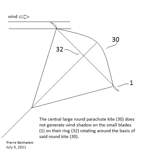
Two power-take-off (PTO) ways are envisaged: by generators aloft (flygen mode), or by rope drive systems. As a start the pressure within the parachute can be useful to ensure some annular rigidity.
I don’t know if it is really feasible: deformations during flight can lead to the requirement of a heavy rigid structure. Initial experiments were difficult but perhaps I am not skilled enough.
And also two counter-rotating rotors are required to cancel the torque each other, in order to prevent the rotation of the central round kite. These rotary kites are far enough each other to allow using fully their respective areas.
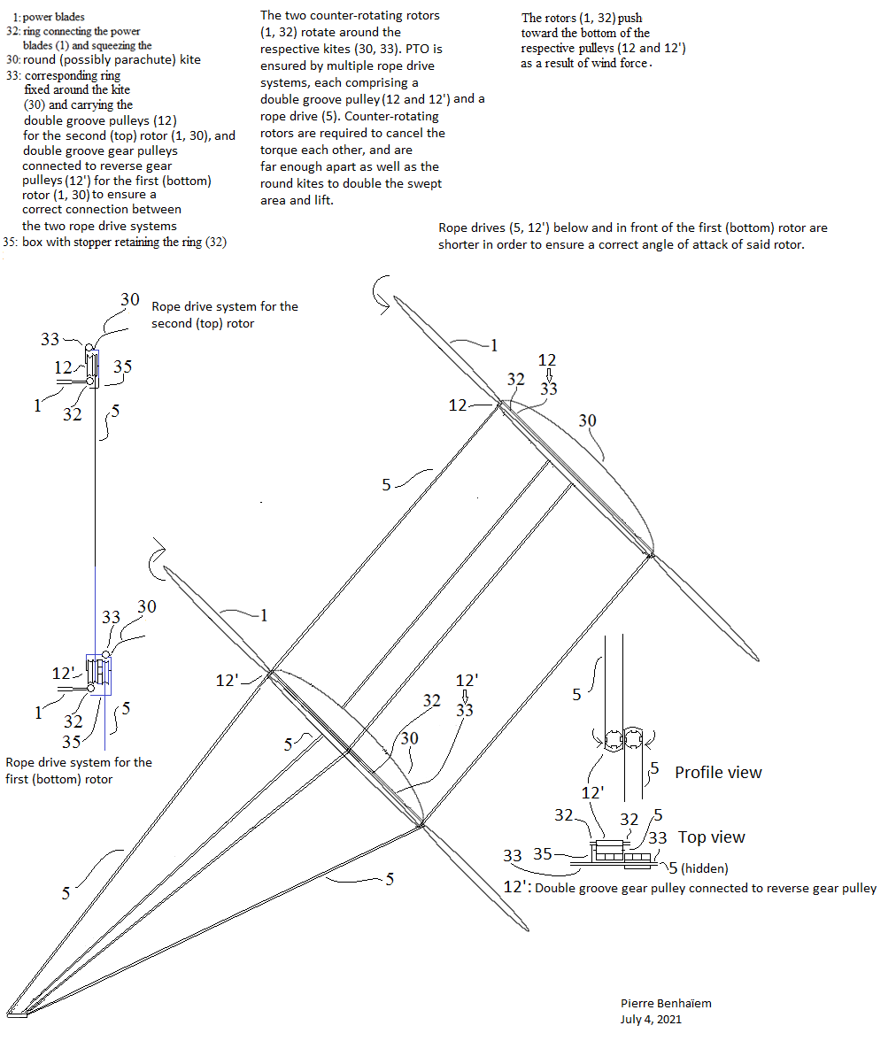
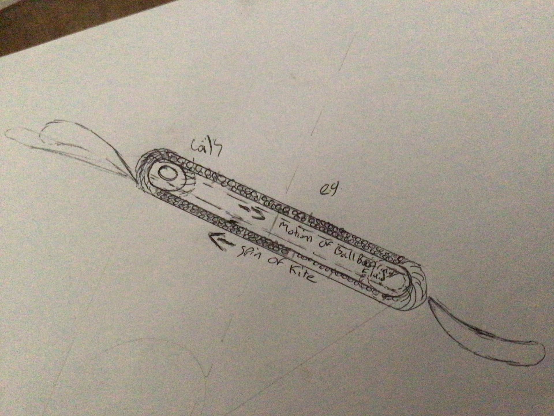
Below is a sketch for a system using rope drive system. The main principle: a pulley has several grooves allowing the conversion of the rotation of the ring of the blades into a perpendicular motion from the kite toward the ground. In addition in the bottom kite a gear is added and is connected to a reverse gear with its pulley in a way that the two rope drive systems are connected from the top kite to the ground via the bottom kite.
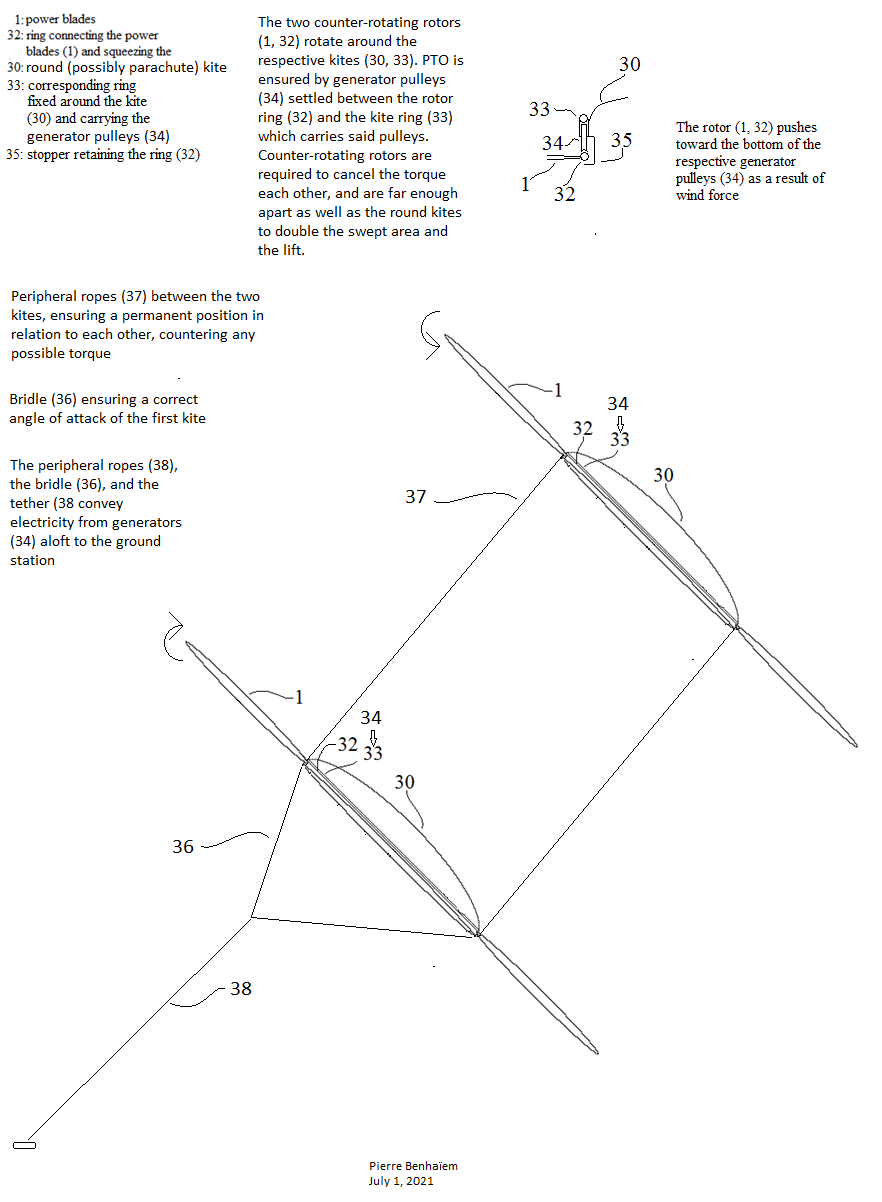
Below is another sketch with generators aloft (flygen mode). This system is heavier, but not too much if light, high speed and durable generators are used. Take-off is also easier by using generators as motors.
Thanks for your possible observations.


")
