Scaling in numbers rather than size

Agreed. The error is to presume traction power is not power-

PierreB: “The data I have provided show that with the same wing area, power generation is 10 times less than traction power.”

The Arctic sled kites folks haven’t planned to design a drag generator yet.

The npw will need a smaller loop radius to rotate a rig as fast as a higher performance wing. The npw rig will be generating much less power.
I’ve tried this. Ram air vs rigid foam. It has been measured and published on this forum.

This thread is scaling by number.
What other non reciprocal, non line running multi-kite rigs can we devise?

It is likely yours. I said:

The Inuit WindSled team is in fact in current discussion with three AWE players on adding wheelgen power (KGM, UC3M, kPower). The Kiteboard EV is in fact intended to test key ideas hands-on, prior to freezing a specific WindSled design that KGM is working on.

The way for low velocity wings to develop high angular velocity is to pull a belt drive on a small diameter shaft. kPower has several groundgen prototypes that use this method. One can also turn vehicle wheelgens at fairly high angular velocity, like electric train-track AWES schemes.

The Kiteboard EV works this way in regen mode, via its toothed Kevlar drive-belt. The wing is an NPW.

Reeling/pumping downwind is a terrible way to use a great low L/D power kite. SkySails uses up a lot of its raw power advantage over all the hot kiteplanes by its slower higher-drag return cycle. Reeling/pumping crosswind-only is the superior way to harness a power kite.

These basic principles are favored from unit-scale to scaling up in large numbers.

True avg. generation power of the Hydra given in Table 8 was 13.8kW. Pierre only considered total upwind-downwind pumping-cycle avg power, with high retraction cycle loss. Therefore, the estimation of a 200m2 power kite as a nominal to peak-rated MW-class device is not so unrealistic for its pure crosswind peak performance. Dimensionless tether-drag is also lower.

Further, 12msec wind at 500m high is a reasonably low rated velocity, compared to HAWT wind 100m high, often rated to near 12msec.

Its also ok to presume a somewhat larger kite, like 300m2 as a MW-class unit, the primary point being not to presume 1000m2, as a multi-MW wing, is so practical as smaller sizes already proven, for high unit-count kite networks that can approach GW unit class as metakites.

Downwind reeling is a terrible choice of AWES architecture for power kites. Payne and McCutchen USP3987987 crosswind reeling is the better choice.

5.75 kW is the average value given on the table 8. So Pierre considers nothing for that. From this value it is not too difficult to deduce that a similar 200 m² power kite would be a 60-100 kW unit at 10 m/s wind speed, and 100-170 kW at 12 m/s wind speed.

Other arrangements such like image 
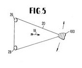
(US3987987 Fig. 5) do not change the fact that the kite generates power when going downwind, flying crosswind or not, with reel or with pulleys.

Pierre,

Just making it clear to readers that the average power of TUDelft’s complete reeling cycle is far poorer than the average generation power of crosswind motion. Even the TUDelft reeling generation phase is sapped by giving up ground downwind.

I consider Payne’s (and Pocock’s) original crosswind motion assumption to be the better design standard, and its also Hadzicki’s chosen load motion in Lang’s 2004 Drachen AWE coverage, and then Goldstein’s choice a few years later. kPower has always been in this camp.

Its true that fans of Kitepower, Ampyx, Kitemill, and other copycats see downwind reeling as a natural assumption, rather than poor AWES design to be avoided.

The average power generation (reel-out) phase value is 13.8 kW, but the average power value is 5.75 kW, which is the number to take into consideration.

Payne’s crosswind motion should be studied but I think the only real difference in terms of efficiency with reeling (yoyo) mode is the almost continuous alternation of the delivered power.

Imho the Scaling in numbers rather than size topic is the siamese brother of the Scaling by size topic.

Yes, and some variants (US6616402, figure 88 for example) of SuperTurbine ™ that are discussed make a good approach of both, although I would prefer a single larger rotor because of a supposed easier management of takeoff and landing and flight operations.

SuperTurbine blade motion is not crosswind to the degree that its axis tilts toward vertical to reach upper wind. The blades have upwind and downwind cycle loss accordingly. ST shaft scaling is especially square-cube limited. The shaft is anything but a “kite made of kites”. This is an especially poor choice of Metakite basis.

The figure 88 (among other similar figures) of US6616402 for SuperTurbine ™ represents a TRPT. There is only tethers, not central shaft. So your square-cube limit does not occur.

Pierre,

The excess ST rigid mass is simply shifted to the spacer spars needed to hold the lines apart, much like Rod and Christof apply spars. Let these designs try and scale further for the square-cube scaling penalty to be starkly revealed.

Compare with this better Metakite model-

You see a problem for scaling. I see a problem for the management. You can be right. The photo is nice but where is the power generation?

Scaling has always been a critical Aerospace/Aeronautics Engineering concern. My scaling analytics fundamentally derive from that culture, not subjective personal insight.

It will be nice as more AWES developers acquire a specialized aviation scaling background to inform their assumptions.

Scaling is a problem to solve, rather than guess at and get wrong. We must scale AWE successfully to power the world with wind.

I’m currently recycling 2x 3 blade Daisy rings, into a 1x 6 blade hexagon configuration.
Scaling by number has the advantage of modularity.

But another advantage occurred to me which I don’t think has been mentioned here. Flutter.
Surely because a short span section is stiffer it will suffer less from flutter at the speeds it will be going.
Can use of short span sections in our speeds eliminate flutter?
@rschmehl would you agree with this?
Your paper Aeroelastic analysis of a large airborne wind turbine goes deep into flutter analysis.

The most basic quote from Variations of flutter mechanism of a span-morphing wing involving rigid-body motions


ChaoHUANGa
ChaoYANGa
ZhigangWUa
ChanghongTANGb
As anticipated, a continued decrease in the flutter speed accompanying the increase in span length is observed.

I’m going to attempt to sound knowledgeable by saying BFF means Body Freedom Flutter not Best Friends Forever
and BTF bending torsional flutter not …?

In the kite Turbine rotors I’m making, there is cyclic loading on the tethering and through the blades.
The 5 point bridling is quite wide spread and set in 1 position for stable driving through the rotation despite gusts. Haven’t noticed flutter. Wouldn’t have a clue till it hit me on the head though.

Is this idea of flutter prevention by span reduction at our given speeds a valid supposition?

Also, it was the recent post with mention of using a hanglider put me onto this flutter research…
http://forum.hanggliding.org/viewtopic.php?t=3863
Operating at higher altitude will give increases likelyhood of flutter … is that right?
At altitude, where TAS is higher than IAS, aerodynamic damping is weaker than at lower levels (damping is proportional to IAS) whereas inertia-induced disturbances are stronger (inertia grows with acceleration, which is the time derivative of TAS).

Read more: http://forum.hanggliding.org/viewtopic.php?t=3863#ixzz6ExoPxD9M

1 Like

I suggested it before, thinking it can be a simple way to scale in number (and rotor diameter ?) without adding too much complexity and weight. That said I have no answer in regard to the flutter issue, but @rschmehl likely has it as you guess.

Thanks @PierreB
Yeah, the ring design always had 6 lines down and @Ollie said the solidity was so low with those blades that the 6 blades on that diameter and speed would be fine.
Hopefully, we’ll know more soon. Some fine knot-work and duct tape bodging on the way… I’ll wear a helmet.

Hi @Rodread, it sounds like a fair general conclusion that stiffer blades increase the flutter speed. You should find some information about this from wind turbine aeroelasticity studies. Best, Roland

2 Likes

Scaling in size can be limited for rigid wings due to the cubed mass increasing as they scale. So scaling in numbers look to be a good way if unities can avoid collisions each other.

So I wonder if using suspension lines to relieve the structure can be a way to connect the units. In such a way the area could increase without cubed mass penalty. Connection elements should be flexible enough to avoid breaking everything.

The sketch below does not show the dihedral angles due to the force of the wind between the fixings on the respective fuselages.
Rigid kite in several connected unities sustained by suspension lines

If this concept is workable some other combinations can be found, such like other wings
instead of stabilizers, or biplanes.

In scaling a wing that long at high speed,
I suspect flutter is going to be a problem
That was one of the key points in Florian Bauer’s analysis of the Makani archives…

Remember that the Makani wing system had a split bridle to the sponsons/fuselages…(can’t remember their term)

1 Like

True. Perhaps using a flexible and hollow hinge between the cords of two wings, and the same for the other wings, but it is likely a not workable solution.

1 Like