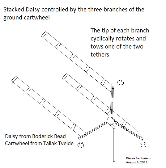
This is an idea for the control from the ground, of three stacks of kites as the three blades.
The cartwheel is both an element and a term coming from @tallakt’s The Pyramid I use with some modifications. Daisy comes from @Rodread of course.
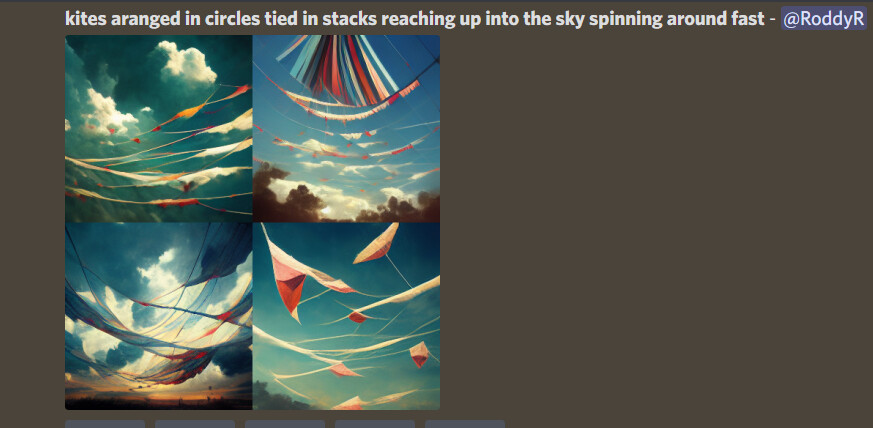
The tip of each branch (or blade?) of the cartwheel can rotate in order to tow one of the two tethers which control a stack of flexible kites like the ones on the video below, but more spaced. I don’t think this would be adapted for rigid blades or gliders, at least for now.
I guess the chief advantage of this approach over a typical daisy ring is
It’s easier to stop the rotation with “individual” stacked blade control so clearly presented.
Scaling the ground station should also take tensile design considerations.
This would be lighter at scale (generator would shrink too)
Its easy for me to get in a track where I say why this is «wrong» relative to «The Pyramid». So I will start there.
The first thing I wonder is why no «spread» of the three legs? This means the cartwheel must be relatively large relative to swept area. But if you do this, the closest kites to the cartwheel will be moving slower than the further away kites.
The triangular bridle is missing. This means that at the highest scale gravity slowdown may lead to an uneven speed. Which againmay lead to stall or reduced performance before the desired scale is achieved.
«The Pyramid» builds on high efficiency airfoils to achieve a longest possible shaft within a limited design room. If you opt for less efficient kites, the maximum length of the tether is reduced. Maybe you could compensate for this slightly by having the kite train, but moment transfer may still be an issue. But my calculations no longer hold because the tether tension with this design is distributed from high close to ground and low at the top.
For «The Pyramid» the launch/land story is very clear. Not so [yet] for this one.
Thanks for your observations @tallakt . I made this design a little quickly. Some concerns came to my mind just later. I think it would be comparable to Daisy (but with the inversion of the way of stacking) rather than The pyramid.
The only way to do without the basic transfer rings to access the controllable branches is to enlarge the cartwheel diameter. I keep a short length of attachment in the lower part because of the low efficiency of the kites you pointed, thinking also that the kite train would increase the length of the whole.
Indeed the bridle is missing.
Yes, I assume the cartwheel must be relatively large for this use, leading to some issue. But we avoid the transfer rings. Balancing between the two issues, allowing some top kites to spread the swept area, counting on the slight wind gradient?
Indeed the kite train can extend the range of the set. The cartwheel should be robust and large.
For me too, at least for this one.
To resume: larger cartwheel vs transfer rings. Adding the possibility of control by the branches of the cartwheel.
That is ok. I realize its a work [idea] in progress. It is a very interesting idea though, exploring amongst other things, what if the cartwheel was bigger. I’m not sure an even bigger cartwheel is a problem. With “The Pyramid” I felt I was pushing things quite a bit by introducing both a tower and a large cartwheel on the ground. But I did not really investigate to what extent this is a problem, and whether it may also be enlarged even more at reasonable cost.
It would have been interesting to see what \Lambda value you would see here, though the whole concept of \Lambda breaks down a little bit with kite trains like you have. You need a more detailed model to understand it. I presume that you could also quite easily add some triangular bridles here and there, in particular if the looping diameter is the same as the cartwheel diameter.
The design room here seems quite large. The one thing I was thinking about when I was working on “The Pyramid” was to make the simplest possible configuration so that it may easily be analyzed. I see here we are diverging from that into something more complext but nevertheless interesting
@Rodread , I think I remember you wrote that the length of stacked Daisy rotors could be unlimited in theory. Can you please confirm this? And what do you expect in the real world as a rough approximation (length to diameter ratio), even if you already provided some elements? Thanks.
Some other elements about kite trains, but not complete data nor simulations to my knowledge:
Concerning Λ value, my first thought is that it should be determined by the length of the two tethers (which is identical) from the cartwheel to the first kite. Then it will remain to model the kite train to integrate the data. To do so, we should start by finding several train coefficients (starting with the lift per unit of the train / the lift of a same unit taken alone without the train) according to several criteria including the spacing of the units, aerodynamics… In reality we do not know precisely the potential of a train of kites.
Yes, this stacked Daisy would be actively and cyclically controlled by the three branches of the ground cartwheel, as the title of this topic partially says. This control would be achieved (see the sketch) by using the tips of the respective branches and which are rotatable. For each branch one of the two tethers is on the internal fixed part of the branch; the other tether is connected to the rotatable tip. When the tip rotates, the tether length is modified, leading the kite to turn.
Without the band(s) around the set of kite stacks and With each of the kite stacks able to be steered,…
You may want to change the output shape of your PTO to being a flat ovoid track. (like a running track on its side)
It’s seems less necessary now to maintain a circular flight path.
In terms of cyclic blade control, pitch for angle of attack is the most desirable one, but not necessary if you retain the bands. Bands are great for maintaining the speed across all of the blades and keeping course without control. The bands (or inflating pressure lines) prevent tangles.
As for how high (far) a kite rotor stack can stack. It is certainly not infinite. With length You require more inflating pressure towards the base end of the stack to maintain torque transmission against torsional compression. This implies wider bands, more banked kites, shorter rotor spacing and more rigid TRPT band mass low down on the overall turbine shaft.
I’ve written all of that in a very assured tone.
No idea. But we should find out.
If I understand you right, there are also the options of having the cartwheel tilted relative to the centerline (not 90 degrees), and of course just a small winch controller mounted at each arm of the cartwheel.
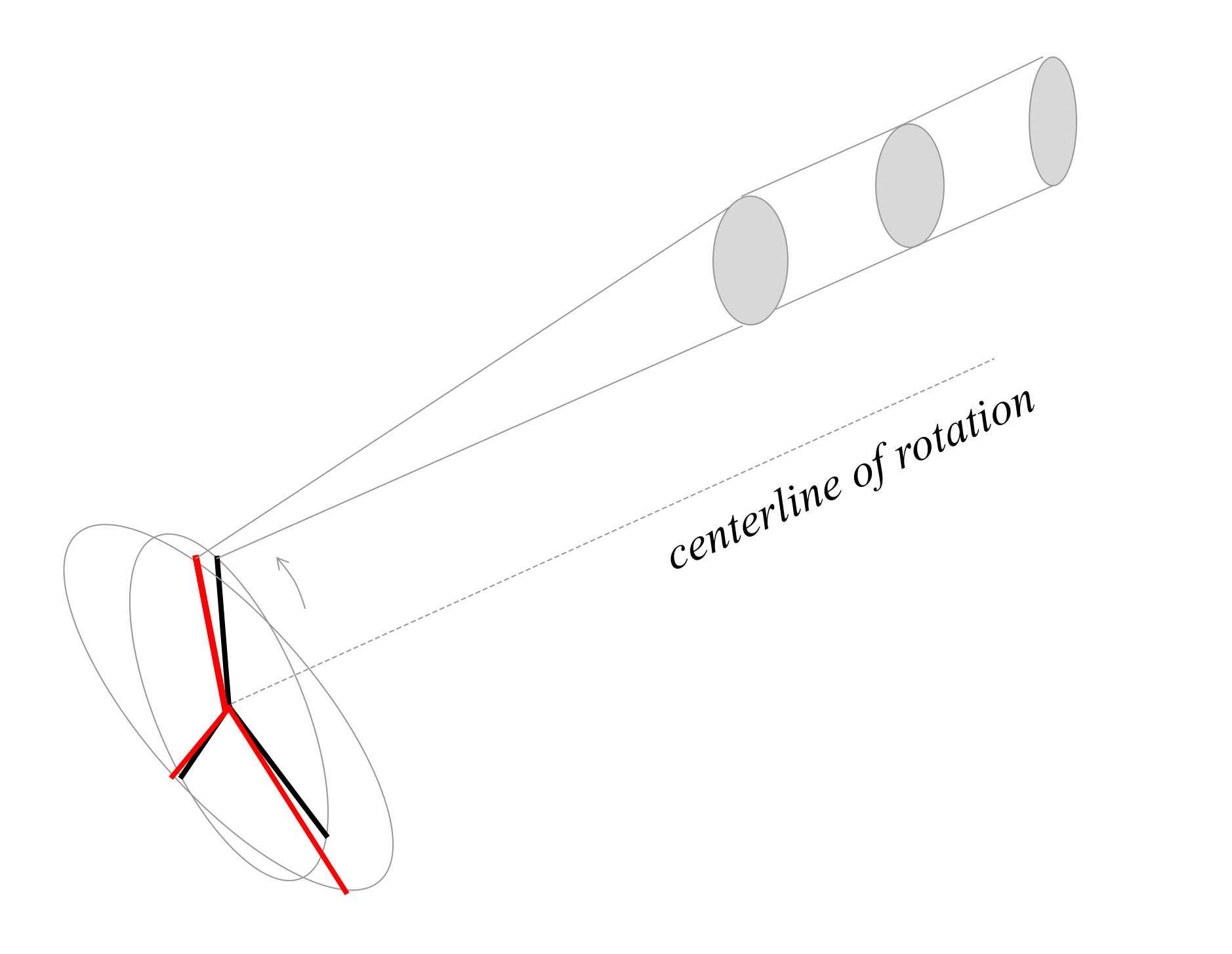
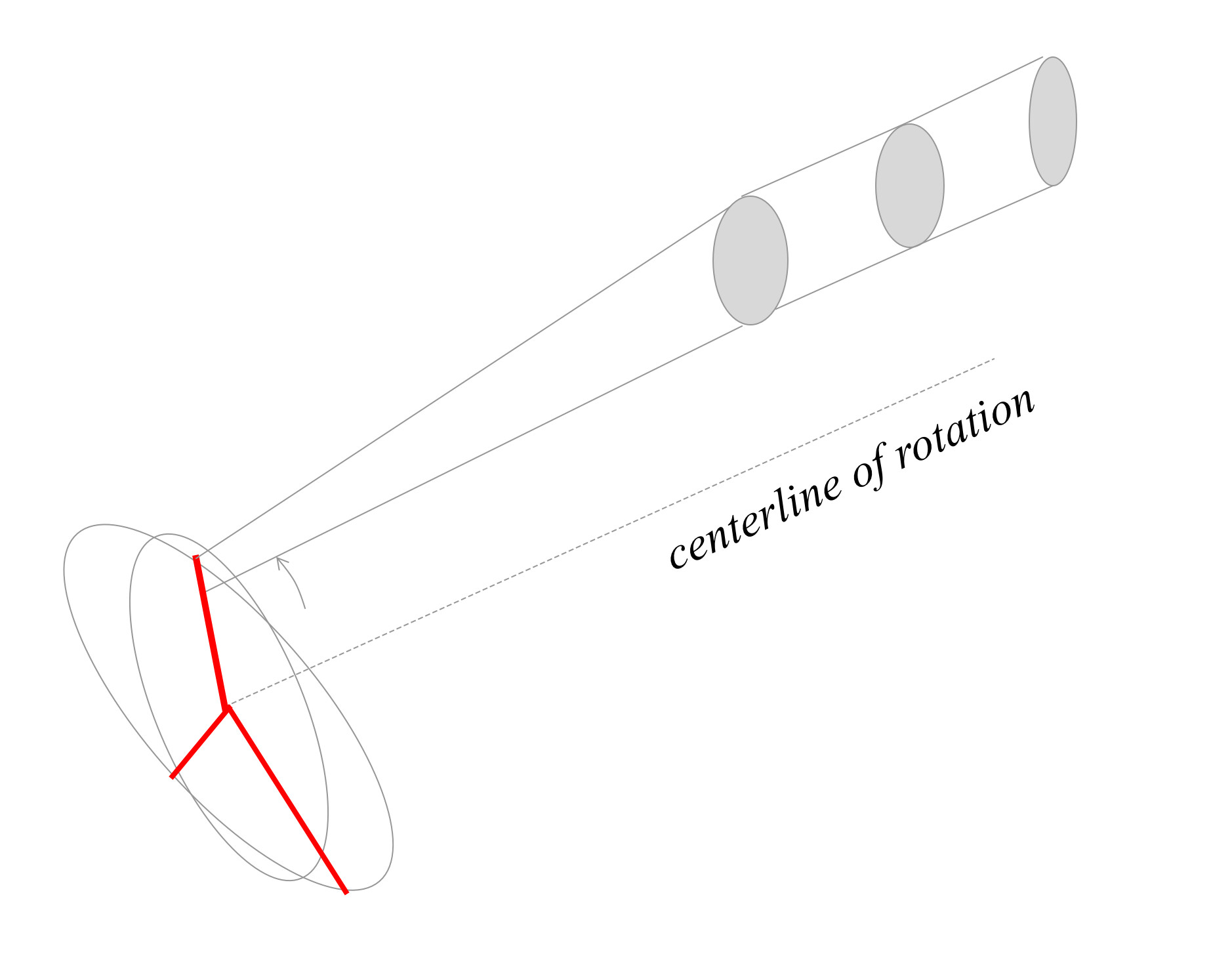
I would also like to propose a “novel” approach in this sketch. I am considering mostly control of altitude/elevation angle here.
To explain briefly, we now have two cartwheels which are rotating in sync but are at an angle with eachother. One is perpendicular to the centerline, the other rotated by an angle. In this way, the line from the “red” cartwheel acts as a control signal while the “black” cartwheel remains constant.
Note the axis of which the “red” cartwheel can be around any angle 0 - 360 degrees, though probably it would be sufficient to rotate aroune an axis at a fixed angle…
I think also it is desirable to have one main line holding all the force of the kites, and one steering line that just controls the roll angle in some way.
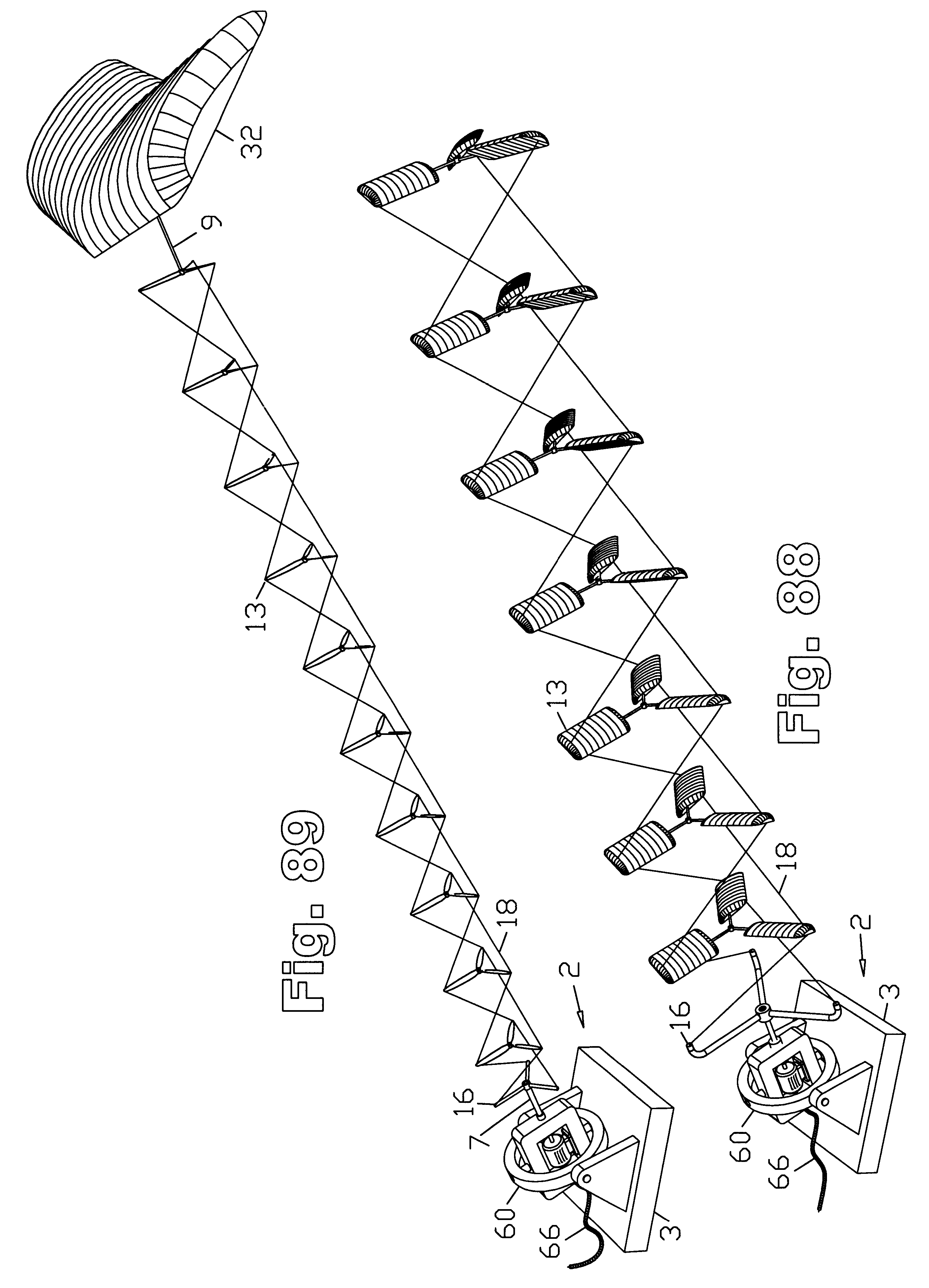
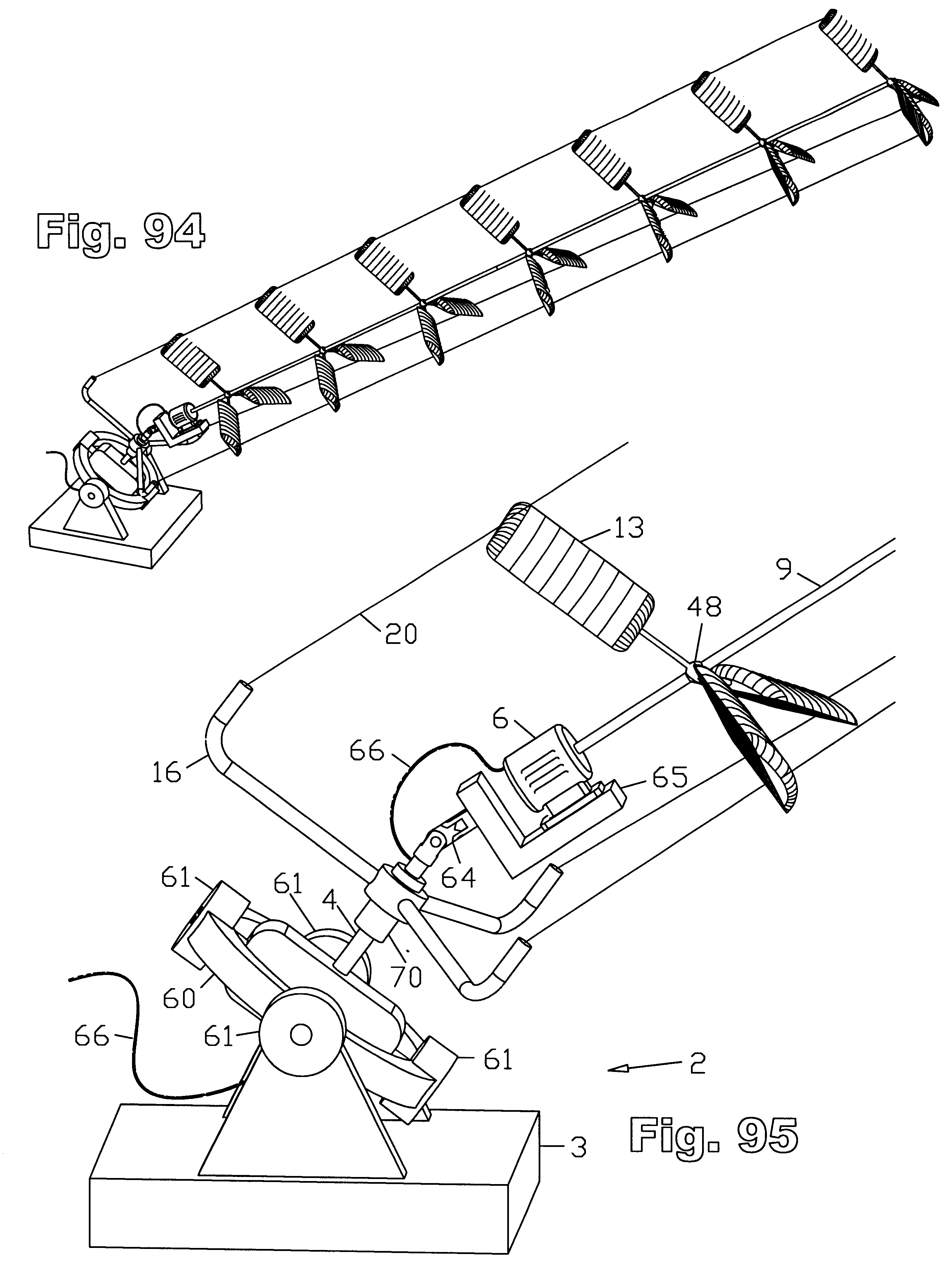
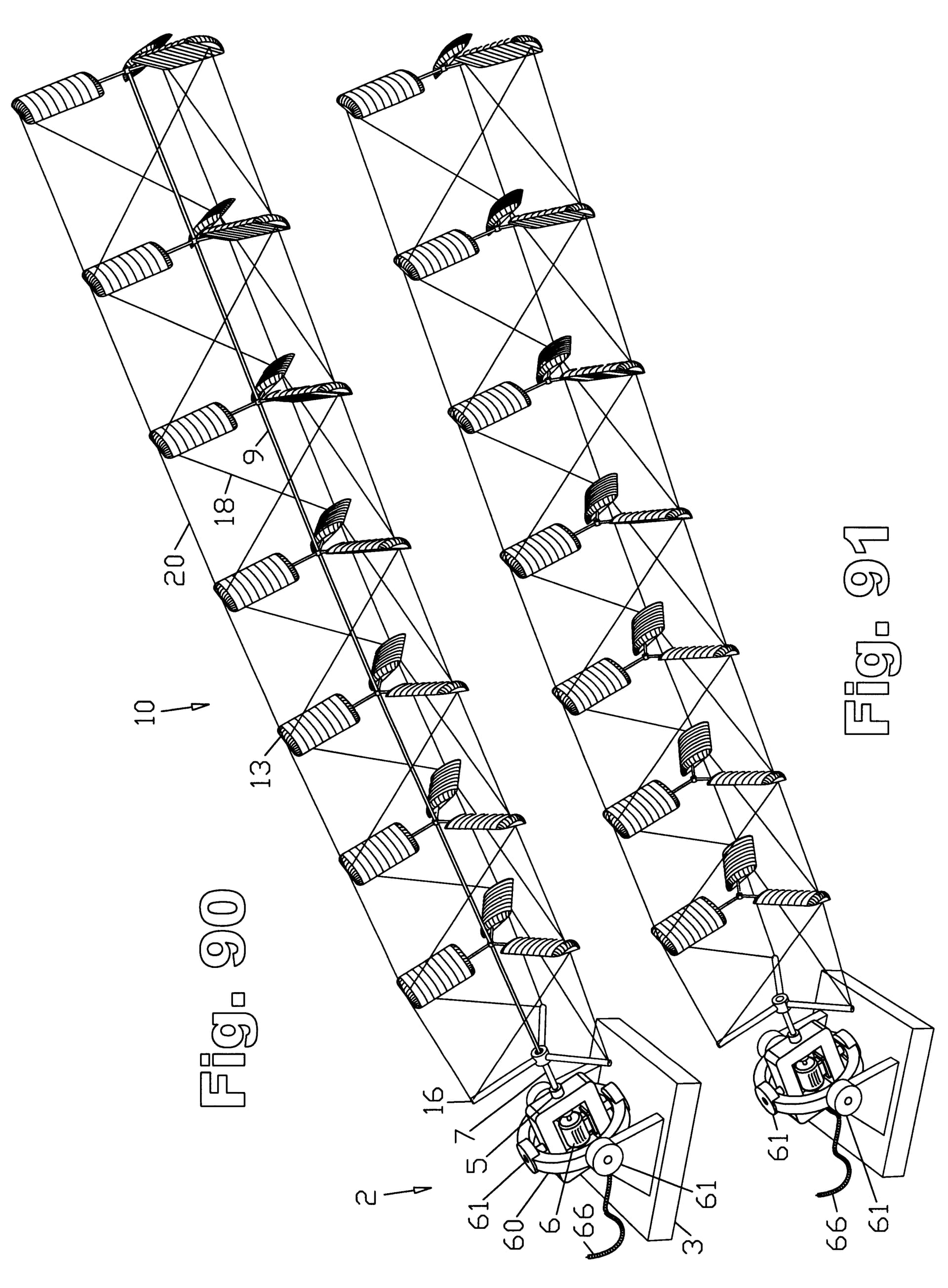
Thinking ahead, I would actually believe something like this could work
Hi Doug: yes, it is something like this. The armatures 16 = the cartwheel, and they should contain some elements (winches, rotating blade tip) in order to cyclically control each blade, making lifter kites or helium unnecessary. For that the three stacked TRPT blades should be separated. If that doesn’t work, we will come back to your patent again.