The Pyramid

I am spilling the details of my “Superturbine” that I have been working on lately, also in cooperation with @Rodread and Oliver Tulloch. It will be presented at AWEC21 in Milan in June.

Please find the complete detailed description here [44 pages].

I would like to describe some high level findings.
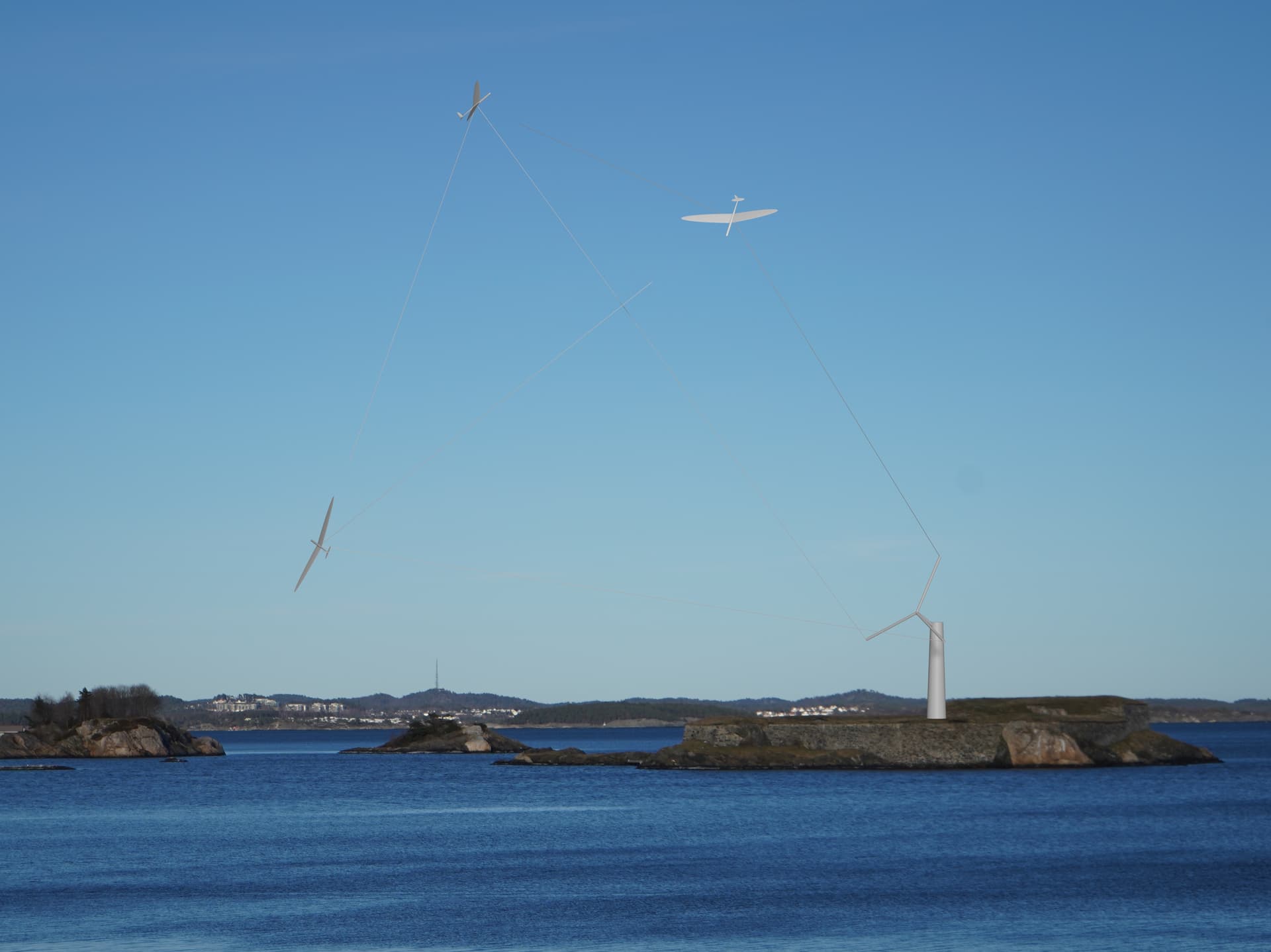
The Pyramid is/has:

  • a three kite AWE architecture
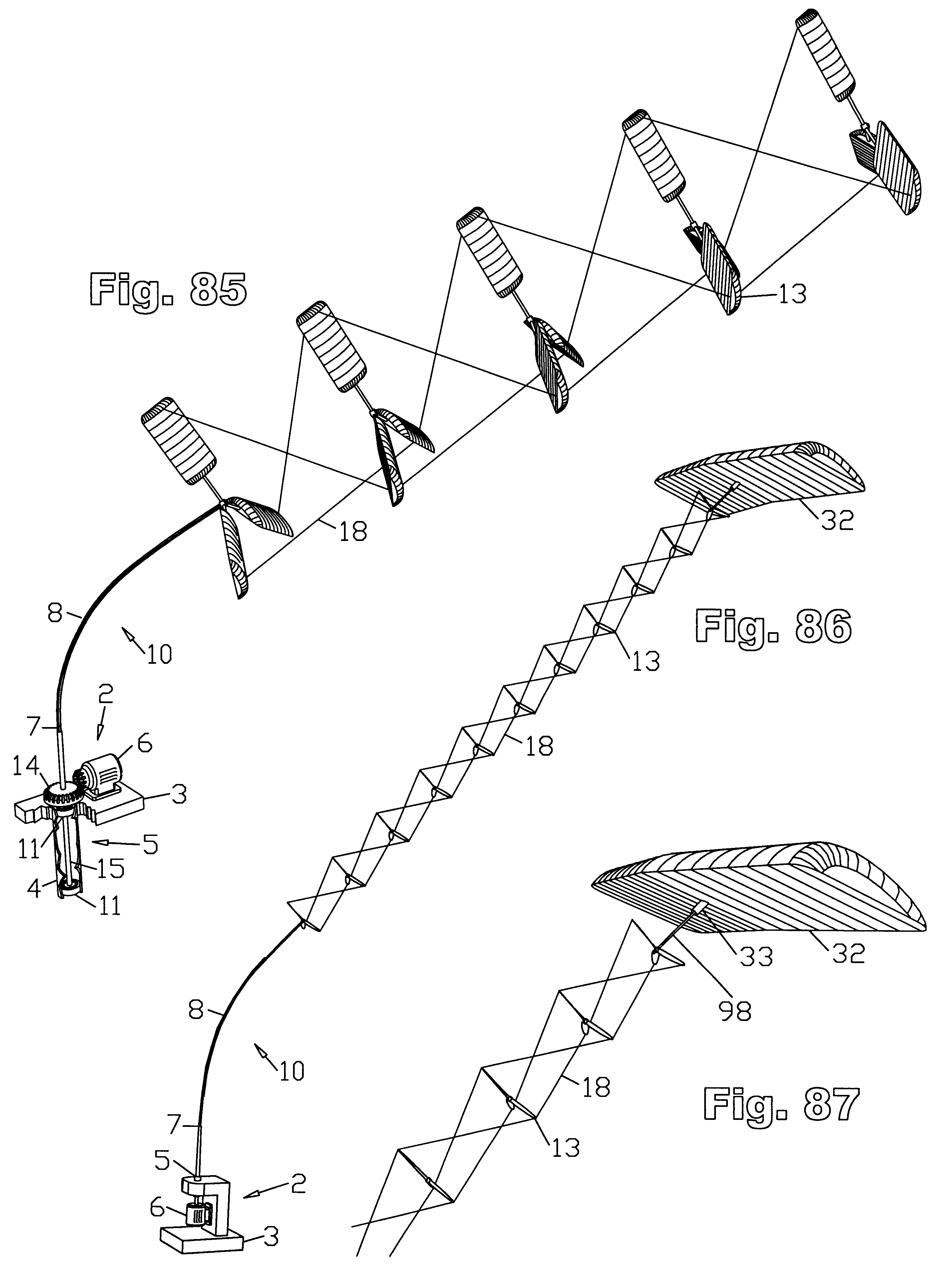
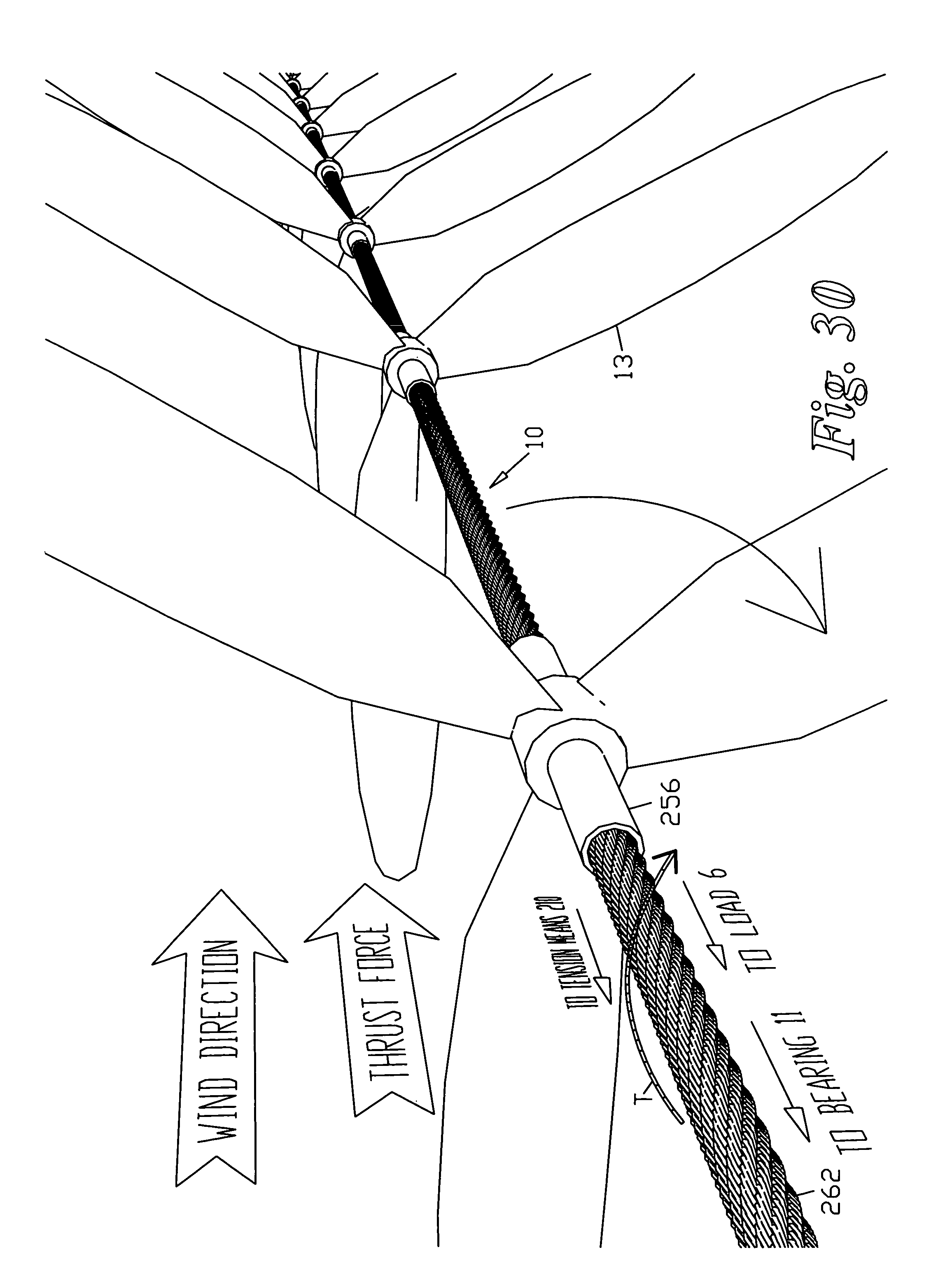
  • a TRPT shaft (rotary moment based power transfer) with three tethers
  • a triangular bridle between the kites
  • a rigid cartwheel at the ground
  • the cartwheel raised slightly by a small tower
  • active kite control to ensure constant tether tension and elevation control by rolling the kites
  • a sane way to launch and land (presumably)
  • no rigid elements in the shaft or otherwise airborne

In addition to all this, the Pyramid is a simple platform to learn more about TRPT architectures, as it’s “the simplest possible thing” with that starting point.

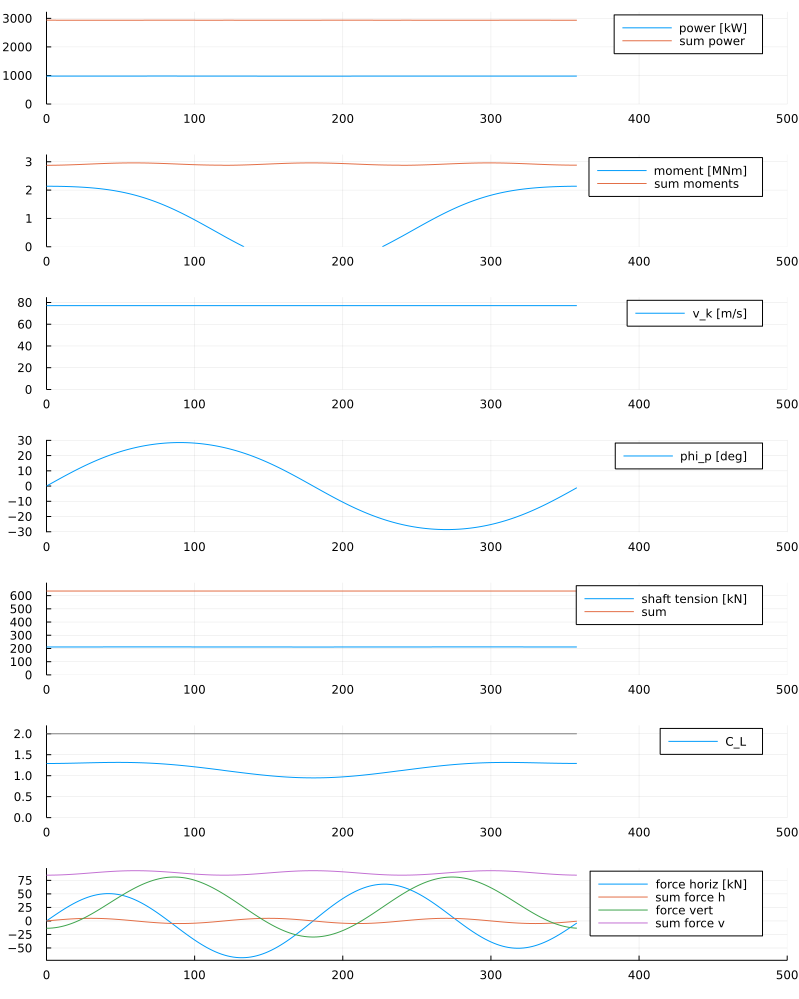
In the document we see that the moment bearing capability of a shaft may be described by the \Lambda value, representing the moment transferred in the shaft divided by [per] tension and kite looping radius. Any TRPT shaft may be assigned a \Lambda value even if it contains rigid elements, multiple sections etc.

The maximum \Lambda value for these kinds of simple shaft that we are looking at here with tether length l, ground radius r_0 and kite radius r_1 is given by

\hat \Lambda \approx \frac{r_0}{\sqrt{l^2 -r_0^2 - r_1^2}}

The maximum power of the rig is generated when the \Lambda value approaches

\Lambda_{opt} \approx \frac{1}{2 \frac{C_L}{C_D}}

Note that C_D in this respect contains drag of both kite and tether.

We also show that the TRPT shaft, when scaled in every dimension by a factor x, can transmit power scaled by x^2. This will exactly match the power production capability of a kite scaled in wingspan by x and in wing area and power output x^2. So the match between the two could scale “forever”.

Then there is a description of a control algorithm to keep tether tension constant, and to provide an elevation angle.

Then there is a simulator which is, if I dare say, quite decent, open sourced at https://github.com/tallakt/TRPTSim

There are mentions of the trouser mod and umbrella mod to reduce tether drag at the expense of reduced \Lambda for the trousers mod, and vice versa for the umbrella mod. Both without requiring any rigid airborne elements.

Even more then, there is a discussion of the feasibility of the architecture given the inherent drag of the tether along with the fact that to get the correct \Lambda values with long tethers, the system drag must be kept low. This is shown to be ok within a certain design window. Also, introducting the tether aspect ratio \varrho = \frac{l}{d} with l being tether length and d being the diameter, the design window is plotted in a nondimensional plot valid for any scale of the design.

In short - this is possible. Until square - cube mass scaling gets the best of us.

Enjoy!

3 Likes

All roads lead to SuperTurbine! :slight_smile:

1 Like

By the way I did click on the link.
It says Tensile Rotary Power Transmission was described first by Oliver Tulloch.
There are many versions of “tensile rotary power transmission” in my original SuperTurbine patent. Here’s just one page of many:

2 Likes

I believe Oliver Tulloch was the first one to use the term TRPT, that is what I am referring to.

@dougselsam used terms of “torque transmission lashing” (column 40, line 1 for FIG. 86 and 87, and at several other places for other figures like FIG. 88).

In the second AWE book:

@Rodread mentions “tensile structure to directly transfer rotational power from a rotating kite configuration to the ground station” (21.1, page 517);

@rschmehl and me used the terms of “tensile torque transmission system”, (22.3.1 page 543).

Indeed @Ollie mentions TRPT in his publications, comprising his thesis until the title: “Modelling and Analysis of Rotary Airborne Wind Energy Systems - a Tensile Rotary Power Transmission Design” (I have added the initials (TRPT) in bold), designating (pages 35, 36, 37) Daisy kite (also chapter 21 above), Rotating Reeling Parotor (also chapter 22 above), and @someAWE_cb OTS as TRPT designs, mentioning also (page 38) SuperTurbine ™ but in the central shaft version.

Congratulations @tallakt for this work. Some question: as the transmitted torque leads to a phase lag of the tethers, and assuming the radius of rotation of kites (flying rotor) is several times the radius of the cartwheel (ground rotor), assuming also there is no rigid part between both rotors, do you think a problem of torque transfer could occur? I precise I have not still read the whole publication, so the answer could already there.

1 Like

The radius of the cartwheel must be quite large and this indeed seems to be one of the biggest drawbacks with the design. In fact torque transfer is not deemed the most pressing problem, rather fitting the wingspan of the kite on the cartwheel when parked. So for this reason I assume minimum cartwheel is 1.5x wingspan. Of course I have no idea if this launch procedure is really feasible in this small radius now.

The phase \theta yields the most moment when ninety degrees. I expect an implementation would know exactly the phase of the kites and cartwheel and ensure that it does not exceed 90 degrees.

Because the cartwheel is «too big» relative to the needs of moment transfer, drag reducing methods such as tether fairings or «The Trouser Mod» are probably of some interest if this should catch on

1 Like

Really hope everyone going to AWEC is reading all this.
So I can just show up with pretty pictures, some chat, a smile and claim to have been really helpful

1 Like

I think there should be no doubt that your and @someAWE_cb efforts have been a huge influence on this. I am just improvising over a known song…


In the above illustration, the letter T refers to a combination of torque and tension, where the driveshaft itself comprises a “TRPT”. When I use a high-tensile strength steel driveshaft, it is still a “TRPT”, which is why we use high tensile strength steel. The hubs are still rings, the tethers are all wrapped in an elongated ring (cylinder) configuration, with the diameters chosen to minimize weight, cost, tether drag, and tether wear.

  1. Twenty-Second Embodiment Driveshaft Constructed from Oriented Strands; FIGS. 29, 30
    Driveshafts made from fibers or strands preferentially oriented to best provide longitudinal stiffness, to bear and transmit the forces of rotor thrust and torque, and of driveshaft tension if the configuration places the driveshaft under tension, have advantages of lower weight and higher performance, compared to driveshafts constructed of homogeneous materials. In our experience to date, filament-wound composite shafts provide optimal high strength, light weight, straightness and stiffness, as well as a consistent bending response when rotated. Longitudinally oriented fibers 260 serve best to impart longitudinal stiffness, while helically wrapped fibers 262, aligned with the aggregate cumulative rotor force T at any location along the driveshaft, serve best to transmit torque from the rotors 13 to the load 6. Such a driveshaft may be supported over a span by its own stiffness, by being placed in tension, or a combination of the two.

For a driveshaft in tension, a structure as simple as a common stranded, twisted steel cable, also called wire rope, or a rope of any sufficiently strong fibrous material (FIG. 30) may suffice. The lay of the strands may be right or lang. Fortunately, wind turbine rotors traditionally rotate to the right (clockwise) when viewed from upwind, and steel cable, wire rope, and other types of rope, is most commonly twisted in a right hand direction, meaning that a common cable has its strands naturally aligned in the proper direction to serve as the driveshaft of a co-axial, multi-rotor wind turbine, transmitting the torque of the rotors to the generator under tension, provided that the generator is located at the upwind end of the driveshaft. A sleeve 256 surrounding the cable may be used to mount each rotor 13.

1 Like

I think no one is claiming to have invented rotary AWE. @Ollie just gave these shafts a name in his paper thats all [also not suggesting that that was all he did in his paper].

Also I think the drawings you are presenting have only a slight resemblance to «The Pyramid» so I’m not sure where we would be heading with this.

«The Pyramid» is a design but it is also an analysis and perhaps a starting point to stucture the way these things could work. «The Pyramid» is a design also, chosen to be simple to implement and analyze. You could not easily remove anything and the concept still be similar I believe. I hope it’s close to the simplest thibg that could work [in this manner]. But, I have and I expect you also have, many ideas for variants that could be a better design. Say, eg. lets add tether fairings and make the shaft longer. But with 44 pages already it’s not the place to try to cover every variation. That could maybe come later.

1 Like

Hi Tallak:
I did not mean to imply this was a version of your “pyramid”, just still responding to the whole “TRPT” concept, which I have always had trouble remembering exactly what the letters stood for, but saw it as a previously-disclosed aspect of the concept I introduced. Also illustrating how “All roads lead to SuperTurbine” in one form or another, which, whether it turns out to be true or not, is a neat slogan. To me, whether someone thinks they are “inventing” a “carousel”, a “daisy”, a “TRPT”, a “pyramid”, or just flying kites in a circle, they are all just elongated wind turbines reaching up into the sky, all versions of the SuperTurbine concept, which was the next step forward from what was later called “laddermill”. I still love the “laddermill” idea, but it seems that various versions of SuperTurbine, with both good and not-so-good aspects, have been easier to implement thusfar. Yes I agree that one could spend all day and endless pages with variations on the theme. Something that works well and doesn’t self-destruct is a nice place to start.

1 Like

I think actually «not self destructing» is a potential feature of «The Pyramid» and other AWE. While a HAWT has huge moments focused on a central hub, AWE are more loosely coupled as each blade/kite is only connected by a tether which is inherently flexible.

This must be weighed against other problems such as crashing risk and the risk of actuator failure. But maybe these are more manageable than the hub durability issue.

If this turns out to be the case, it could be that other «traditional» AWE benefits such as higher altitude winds, less mass in build etc are actually less important. Because I think durability had been HAWTs achilles heel historically.

@dougselsam your work definitely kicked off that direction for rotary AWES (Airborne Wind Energy Systems)

The main difference in this Pyramid thread - is thread (i.e. not rigid)
It’s going for large radius flight without rigid coupling between blades
And no rigid composite material to assist in TRPT (Tensile Rotary Power Transmission)

The large swept area being very desirable for efficiency
The large radius TRPT being very desirable for torque transmission capacity
and pure tensile TRPT for lighter AWES which have better performance

2 Likes

This is also a step in the evolution of TRPT.

For @dougselsam patent: there is tensile rotary power transmission between the stacked rotors (Figures 83-91), and also in the basis (Figures 83, 84, 88, 89, 90, 91) but the rotors themselves are rigid.

For @Rodread : TRPT extends to the connection of the blades within a rotor (in spite of some thin rigid elements), in addition to the TRPT in the whole system (including rigid torque rings in the basis).

The Rotating Reel System (RRP) has no rigid part between both rotors, but the rotation is disturbed by the non-parallelism of the rotors. Later offshore and onshore versions with separate wings have been sketched:
hydro-carousel-figure-eight-rotating reel-Daisy.pdf (see figure 3), and the onshore version on:
Rotating Reel divided rotor into wings with disk area.

Perhaps the separate wings could partially solve the non-parallelism by a suitable control, in addition to have a higher L/D ratio. Indeed unlike for a rotor the whole wing goes fast. This configuration is rather close to that of a carousel, but with a direct drive of the ground rotor as for other TRPT and torque transfer rotary AWES. The only (but not insignificant) advantage I could see for RRP and all the variants was the flat horizontal installation of the ground rotor.

The Pyramid has also no rigid parts between the “flying rotor” and the ground rotor, and between the wings making up the rotor. And (as for other TRPT excepted Rotating Reel) both rotors are parallel. So the potential of power is fully maximized (parallelism + high glide ratio of the wings leading to a (advantageously) low Λ value + large swept area compared to the ground station).

A question to @tallakt : what would be the speed of the wing of style Makani 600 kW «October kite» (page 22), at 12 m/s wind speed, knowing the glide number including tether, at nominal CL, is 13.1?

The glide number I am using has drag coeff 1:20 for the kite, then add tether. As Makani uses a conducting tether, things are slightly different here. The C_L/C_D I’m getting though is 10.8, so my simulator should be conservative.

The plot shows the simulator for windspeed 12 m/s giving a flying speed [ground speed] of just less than 80 m/s. That would match a TSR of ~6.7 I guess. Nice to see that I am in HAWT ballpark here.

You may also see that the C_L is not 2.0 as the tether is too thin for that. The algorithm reduces C_L to 1.5 to match the strength of the tether.

By the way the TRPTSim is open source and runs on Julia which is also open source. I added the code to run the plot you see below

julia> let azimuth = 0.0, horiz = 0.0, vr = 13_000, lambda = 0.06, d = 0.022, cfg = config(october_kite(), c_d_fun_coeffs = [0, 1/20], d = d, l = vr * d, radius = 26*3)
         (df, tmp) = TRPTSim.solve_sector_df(cfg, 12.0, azimuth, lambda, horiz)
         plot(size=(800, 1000), plot_solution(df, tmp))
       end
2 Likes

Hi @rschmehl, numerous publications validated until some degree the “two main AWE modes” (fly-gen and yo-yo). As you know a third mode will be highly represented in the next awec2021 : tensile rotary power transmission (TRPT), with @Rodread , @someAWE_cb , @Ollie , @tallakt :

Rotary Kite Turbine Development
Roderick Read, Windswept and
Interesting Ltd ;

Rotation compensator based cyclic
pitch control for Rotary Airborne Wind
Energy Systems
Christof Beaupoil, someAWE Labs S.L. ;

Design Analysis of a Rotary Airborne
Wind Energy System
Oliver Tulloch, University of Strathclyde ;

The Pyramid, a TRPT rethink
Roderick Read, Windswept and
Interesting Ltd .

The last one leads to a new design (The Pyramid) as well as a computerized scientific method to better understand and maximize the potential of TRPT. You will find again some of the elements of the analysis of the now defunct Rotating Reel Parotor for which I thank you and others for shedding a tear :cry:.

I would suggest that each of these four presentations be labelled “TRPT” to allow listeners to make the link, ending with the perspective of the Pyramid.

1 Like

@tallakt ,

Your answer in our private discussion could be plausible. However, I am also considering a reverse hypothesis, taking into account some elements of your publication that have just come to my attention again, as well as elements from the chapter 22 of the second AWE book.

From chapter 22, page 571 and Fig.22.18:

The contour plot and the solid isolines show that the transferable moment decreases for increasing distance between the rotors and that it increases with increasing size of the ground rotor.

Also pages 570-571:

It is evident that the longer the tether system and the smaller the ground rotor the lower the transferable torque.

Now considering your publication, page 3:

r0 the radius of the cartwheel at the ground side
r1 the radius of rotation of the kites
l the length of the tether

pages 6-7:

To go from an value to the actual moment, multiply the Λ value by the looping radius of the kite and the shaft tension.

Page 11, values for I (tether length), then r0 (ground radius), then r1 (loop kite radius), then Λ :

A 200 m 10 m 50 m 0.052
B 100 m 10 m 50 m 0.116
C 200 m 20 m 50 m 0.103
D 200 m 10 m 100 m 0.057
E 400 m 10 m 50 m 0.025
F 100 m 20 m 50 m 0.237

As an example A and D have roughly the same Λ values, respectively 0.052 and 0.057. However in A,
r1 /r0 = 5, while in D, r1 / r0 = 10. And I didn’t find anything in the paper about the transferable torque relationship between r1 and r0. The smaller the radius of the cartwheel at the ground side compared to the radius of rotation of the kites, the lower transferable torque.

So my hypothesis is that Λ values should be multiplied by (r1 /r0). This would result in 0.26 for A (5x), 0.58 for B (5x), 0.2575 for C (2.5x), 0.57 for D (10x), 0.125 for E (5x), 0.5925 for F (2.5x).

The \Lambda is the relationship between moment and looping radius and shaft tension. It depends on r_0, r_1 and l. looping radius and tension are an indication of scale. They should also map nicely to the capabilities of the kites as they scale (though not perfect).

I am not sure what r1/r0 would add in value, perhaps you could mention why this number would be necessary?

I think it is also a good rule of thumb that for long l, \Lambda \approx \frac{r_0}{l}

Also I would like to mention that the idea of having cartwheel radius equal to looping radius is an interesting thought that I did not explore yet. If you do that, you dont need the expanding triangular bridle which may add to robustness and reduce cost.

Also of course the added benefit of higher \Lambda for a given tether length.

If you do that though, tether drag will increase. You could mitigate this eg with the trousers mod, fairings, or making the r_0 variable/motorized.

Another practical result of doing so would be to reduce r_1 as much as possible. This would be in the realm of aerodynamics though.

Sorry for the symbols of the quote. Indeed Λ is defined by equations (13) about “tension per looping radius” and (14) which includes r0, r1, I . But I don’t see r1 / r0 (or the reverse) somewhere.

I think this number is essential because it gives the transferable torque from r1 to r0. As an example, if r1 is x times higher than r0 , the tangential speed at r0 will be x times lower, resulting in a x times higher torque. So the transferable torque from r1 to r0 will be x times lower.

[Λ = approximately r0/I] stands if r0 = r1 (imho). If no I think multiplying it by (r1 / r0) would give a correct Λ value. If you prefer not to include this factor in Λ, you can reverse it (r0 / r1) to obtain the transferable torque from r1 to r0.
Sorry for the symbols.

I think the simplified \Lambda stands as long as l is much longer than the radii. But the value r_1 is only included implicitly, because \Lambda must be seen together with r_1 and tension T_N to be useful in calculations.