Hi Doug, as “partly-airborne” do you mean a Serpentine SuperTurbine ™ with a lifter kite or a balloon? Have you a photo? Thanks.
Hi Pierre
No nothing like that. No kite or balloon would survive our strong winds.
It’s a spring-loaded ST on a pole.
I’d say it is maybe 10% airborne in a strong wind due to rotor tilt.
It’s been thru hell and back with regard to wind, and somehow just keeps running.
Grid-tied. Out there spinning right now.
I would have expected it to burn out the generator years ago, but it just keeps going.
I’ve actually never heard of any turbine this small, lasting this long.
Well if you throw enough spaghetti at the wall, sooner or later, if you’re lucky, one piece will stick.

Some papers about multi rotor and co-axial wind turbines are mentioned below.
Power output prediction and primary evaluation of a unidirectional co-axial series rotors wind turbine: Serpentine on a frame on a tower.
COMPREHENSIVE EVALUATION OF INNOVATIVE MULTI ROTOR WIND TURBINE DESIGNS: @dougselsam turbines are described and evaluated.

Some data from @dougselsam are below:
5-Star SuperTurbine™: 5 five-foot diameter rotors, 5 blades per rotor, the first two spaces are ~7 feet, the second two spaces are ~6 feet, due to a 12-foot section of composite drive shaft, peak output 5000 Watts.
“The wind speed was not measured during this video - we were just checking out the power, which varied mostly between about 2000 Watts and 4000 Watts. This power output level indicates to me the winds were often exceeding 30 MPH at hub height.”
At time 2:33,
if you click on-off, real fast, you can find a little spot where the meters show
43.7 Amps
at 107 Volts
43.7 Amps x 107 Volts = 4675.9 Watts
I dont understand why every paper on wind needs a paragraph on growing needs for electricity production and global warming… just get to the point? People know things
I wonder how much of the gravity of a tilted multi-rotor (SuperTurbine ™, and perhaps TRPT), system can be an obstacle for scalability.
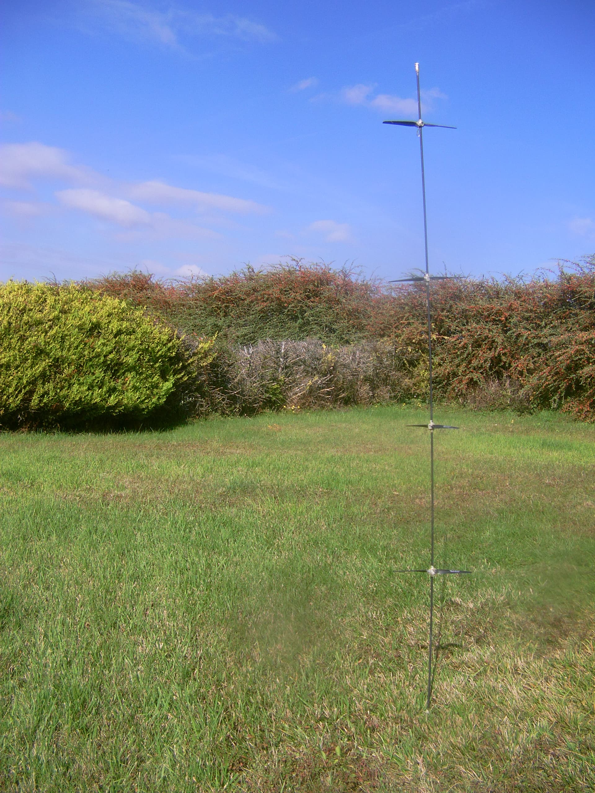
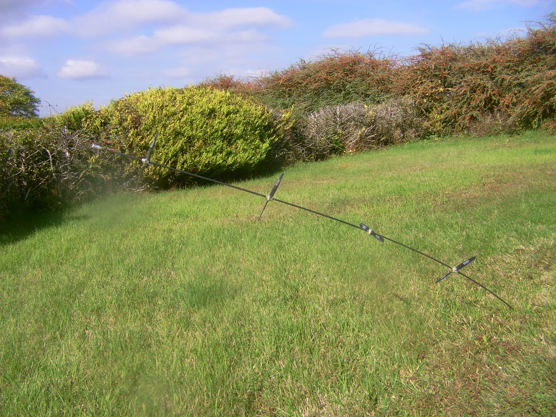
For a preliminary intuitive understanding I have placed two pictures showing a multi-rotor placed vertically, then tilted. One can see the curvature of the axis when the multi-rotor is tilted. And when you hold it in your hand, it is much easier to hold it vertically than tilted.
Indeed, when you hold the multi-rotor vertically, gravity is applied at the holding point, whereas when you hold it tilted, gravity is applied under the different points of the multi-rotor, with an increased lever effect as you move away from the holding point.
As a result, we can perhaps deduce that the more the multi-rotor scales up, the less the elevation angle, the more the lifter kite area proportionally increases in order to compensate the excess of increase of the gravity by lever effect, and also the more the tethers are stretched if the multi-rotor is a TRPT.
On the other hand the multi-rotor generates some lift, but I doubt that this can compensate for the issue of the gravity augmented by lever effect.
Hi Pierre: My earliest experiments were handheld, just a shaft with propellers with no generator, and it worked as follows: You held a section of SuperTurbine™ in your hands, at an angle to the wind so that:
- Each rotor received its own share of wind undisturbed by upwind rotors, and;
- The thrust force pushed downwind and upward on the assembly, so it was a matter of adjusting the angle you held the assembly in your hands, adjusted in real time as the wind speed varied, to keep the assembly from sliding too far back or forward, to avoid the propellers contacting your hands, which would act as a friction brake, slowing the rotation. By constant adjustment of the angle you held the shaft, you could avoid that friction of the propellers with your hands, while the shaft spun freely in your hands. It is fun to do, and it is where you can feel the performance, and see that it needs a generator to control the speed, and produce electric power.
Hi Doug: my comment was about gravity, or the weight (so the mass) of SuperTurbine if you prefer.
On the video below (at 10:52) you can see the downward curvature in the middle (but not close to the generator, and not close to the lifter balloons) while the rotors are not turning. The same but less pronounced curvature remains at 11:15, the rotors turning, despite the lifting balloons.
")
Hi Pierre: There was very little wind that day, which is normal for any time you have a film crew or any interested visitors flying in from another country expecting an “instant demo”, whether or not there is even any wind on a given day. That’s just the nature of wind energy - wind is intermittent, not always blowing hard, and amazingly, your average person is often surprised to realize that actual wind is required to do wind energy. At least there was SOME wind. You might notice that right about 11:00 in the video, just after startup, you see the driveshaft visibly lift and straighten as the rotors acquire lift and thrust force from spinning in the slight, yet barely sufficient, wind on that day.
If you check out this video,

there was more wind (still not a strong wind, but a decent wind) and we used a kite rather than balloons. The balloons work best in low winds when a kite might just fall out of the sky, but as soon as you have a decent wind at all, the kite pulls everything taut, straighter than the balloons could…
![]()
Hi Doug: indeed there is no downward curvature in the middle in this video, unlike the previous one.
That said at about 2:00, the rotors are not yet turning, and at about 3:00, the rotors are fully turning. In both cases, the elevation angle seems to be about the same. It appears that the lifter kite is doing all the job of lifting, unless the shaft is pre-oriented.
Now what I wanted to say on this comment is the issue of scalability due to the gravity when SuperTurbine ™ becomes larger or/and longer.
As an example, assuming that the filmed SuperTurbine ™ is 15 m long, and the lifter kite area is 2 m²: if the SuperTurbine ™ becomes 150 m long with the same rotor diameter and the same number of rotors per 15 m section, the required lifter kite area would be (far) higher than 20 m². It is due to the lever effect of the gravity that increases when the distance to the generator (the anchor) increases. As a result the downward curvature in the middle observed on the previous video could occur even with a 20 m² kite. But this is only a guess.
In terms of Tensile Rotary Power Transmission
You can’t use a rope as a type 1 lever
I don’t think your lever effect applies @PierreB
I don’t think that a TRPT would work so differently from a rigid shaft as for SuperTurbine ™, except for a larger diameter which would attenuate the curvature in the middle, unless it would lead to stop the rotation. Perhaps also the unwanted curvature would be mitigated thanks to the lightness of the TRPT rotors.
To support the mass of the rotors, and thus compensate for their gravity, which (as for SuperTurbine ™) is augmented by lever effect with the length of the TRPT shaft in relation to the anchoring point, an increase in the tension of the TRPT is required, beyond the linear increase due to the length, leading to the requirement of a higher kite area beyond the linear increase.
A solution (for TRPT or SuperTurbine ™) would be the implementation of lifter kites all 10-15 m, although such a solution seems to be difficult if even possible.
Another solution would perhaps be increasing the elevation angle (leading to loss some efficiency).
A sketch below:
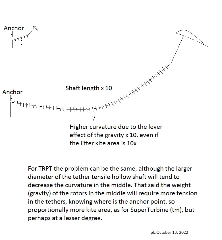
Perhaps the sketch would represent something more like a catenary. That illustrates the downward curvature in the middle mentioned before.
When you suspend a chain from two hooks and let it hang naturally under its own weight, the curve it describes is called a catenary . Any hanging chain will naturally find this equilibrium shape, in which the forces of tension (coming from the hooks holding the chain up) and the force of gravity pulling downwards exactly balance.
The links of the chain in the middle go down further, as for the rotors before: indeed they are farthest from any of the two hooks.
And for a same mass suspended (in the middle) from a rope, the longer the rope, the greater the tension required for the rope to be straight.
This is one reason why even in flat terrain two pylons will not be enough if they are too far apart: either the tension on the cable will have to be too high, or the cable in its middle will drag on the ground by cable sag. This is why several pylons are used. These pylons would be a little like lifter kites all the 10 or 15 m.
Some explains about pylons, then a cable sag calculator:
If you multiplied the Straightline distance by 10 (50 m instead of 5 m), and you divided by 10 the cable weight per unit length in order to keep the same total cable weight, the result will be 10x, leading to a lever effect or something similar.
Thus my question remains:
As for my guess:
The forces from the rotors are the drag by the wind, and the gravity by their weight (mass), but not the lift by their own (without cyclic control) except perhaps the lift aggregated to the main lift from the lifter kite.
So I guess that as they scale, shaft sags occur, leading to the requirement of a lifter kite which ends to be too large, or (perhaps yes, perhaps no) to the requirement of relatively wider shafts (and rotors) compared to the length.
You’ve not included lift from Kite Turbine rotor.
Even when static on the ground it has lift similar to a bol kite. The topmost set of blades is tilted, outer tip closer to the PTO than the inner tip.
Even a slight incline like this is enough to launch a kite.
A bowl kite or a Kite Turbine rotor or Serpentine (SuperTurbine ™) don’t fly without a lifting kite.
@PierreB In this video you posted… They do
The bowl kite remains at ground level for most of the video, rising only momentarily (and very slightly) from time to time.
A bowl kite and anything else that spins (without active control), such as windsocks and other rotors, has no average lift per se, only drag and weight.
And if you lengthen a train of several rotors, the catenary sag effect will increase. The lift force capable of compensating for this sag is only at the other end in the form of the lifting kite which also is lending its lift to said train, but not enough (unless the lifting kite area increases hugely) as the length (and also the additional mass and drag by scaling) of the train increases.
I evoked catenary sag or lever effects. Another simple way to see this is to look at the Leaning Tower of Pisa: it is easy to imagine that if it were to lean any further, it could fall, above all if it was still longer.
Well
Quick check on youtube again

