The first one has a fixed frame allowing AoA by itself.
The second one has a bridle fixed at the front of the rotating kite, also allowing AoA by itself, by using the weight of the kite.
You can add the Gyrokite, having a fixed body and that I mentioned previously:
None of them is a torque transfer system, as specified in the current topic.
Stacked Daisy or Serpentine SuperTurbine ™, and generally torque transfer systems have only rotors, not fixed frame, not fixed body. So they require a lifting kite, or active control.
Oh now you are triple confusing me @PierreB
There’s no AOA adjustment in either of those.
But then the frame of a Daisy or the tilted bridling (set of tethers) of a Daisy don’t count somehow.
This is getting daft
As I clearly mentioned there are fixed parts on the rotor kite (first device from the last set) and the gyrokite, respectively a frame and a body. They ensure a constant AoA. For the second device AoA is ensured by another mean described above.
I precise that the discussion about these three devices (which, moreover, are exceptions) is absolutely secondary, so I will not pursue about it, all the more so as it seems to have been motivated by the main point of my last set of comments, namely the severe limit to the scalability of torque transfer devices that I was able to deduce from the catenary shaft or/and lever effect, and that I will not argue further: just read my comments from here.
I don’t think it is satisfactory enough advice for a novice to this topic to say. Here is one way and potential effect from a semi analogous field which may imply some limit to effectiveness of a method which has yet to be rigorously studied.
Just look at Doug’s two videos: on the first one, you can see that the longer shaft length generates a higher catenary sag effect than on the second video. And I didn’t see any significant difference in elevation angle with rotors at rest or in rotation.
This is confirmed on one (see below) of your videos: we can see at 0:50 and at 1:58 that without rotation the elevation angle of the rotor remains the same or even higher than with rotation. Thus when rotating at 1:20 and 2:15, the rotor loses elevation angle and descends due to the additional drag which is not compensated by the assumed and sufficient additional lift. The lifting kite does all or almost all the lift work.
As the lifting kite is at one end and the anchor (PTO) is at the other end, the catenary sag effect will increase with the length of the shaft.
That said you could take my comments then start a preliminary study to confirm or infirm them, or rather to detail them. Then you can decide what direction is better for Daisy: scaling, or improving it for a possible market.
108 @PierreB
Just 10 seconds later
You see a non spinning rotor post launch but pre brake release close to the ground.
The start of that video states clearly how low the wind and lift tension was that day.
The effects are not as you state.
If any of these stacked kite turbines drag as you say they do it should have been this one 6 years ago
Dave Santos rightly expressed reservations about the ability of torque systems to scale up, citing the cubic mass penalty.
I added that both devices undergo the catenary sag effect which applies more in the middle of the shaft, far to the lifting kite, far to the anchor point (PTO). The longer the shaft, the higher the catenary sag effect, in addition to a greater weight.
I think that explains why after numerous years these two devices remain confined to the same low altitudes.
That said Daisy and Serpentine (SuperTurbine ™) are efficient and fine devices.
Pure rotors (like bol or daisy) without control or adjustable bridling or additional lift have serious limitations.
That I agree with.
They do however have lift when inflated and spinning at a reasonable elevation with reasonable winds.
They’re not steady in the sky without support. As per videos and theory… Up-going side has more apparent wind, down-going wants to be faster. So it’s imbalanced.
They easily slide across, up or down without support.
But they do compensate with more lift (vertical component) and line tension than mass when they’re powered up at sufficient elevation. There is no visually discernable sag induced on the cumulative turbine shaft in good winds.
Guaranteeing sufficient balance of lift from spin at elevation and additional lift from lifting kite for a given wind was not something I pursued a good scientific record of. Too few lift kites in the bag. Yes I knew when it would work and when weak wind meant I was likely going to have a quick crash session.
Plan is now to apply reasoned tech to handle the logic of these launches and landings and improve the system from more robust scientific data.
There are options like complex out of plane PTO tilting control for steering without a lifter - YUCK. Keep it simple.
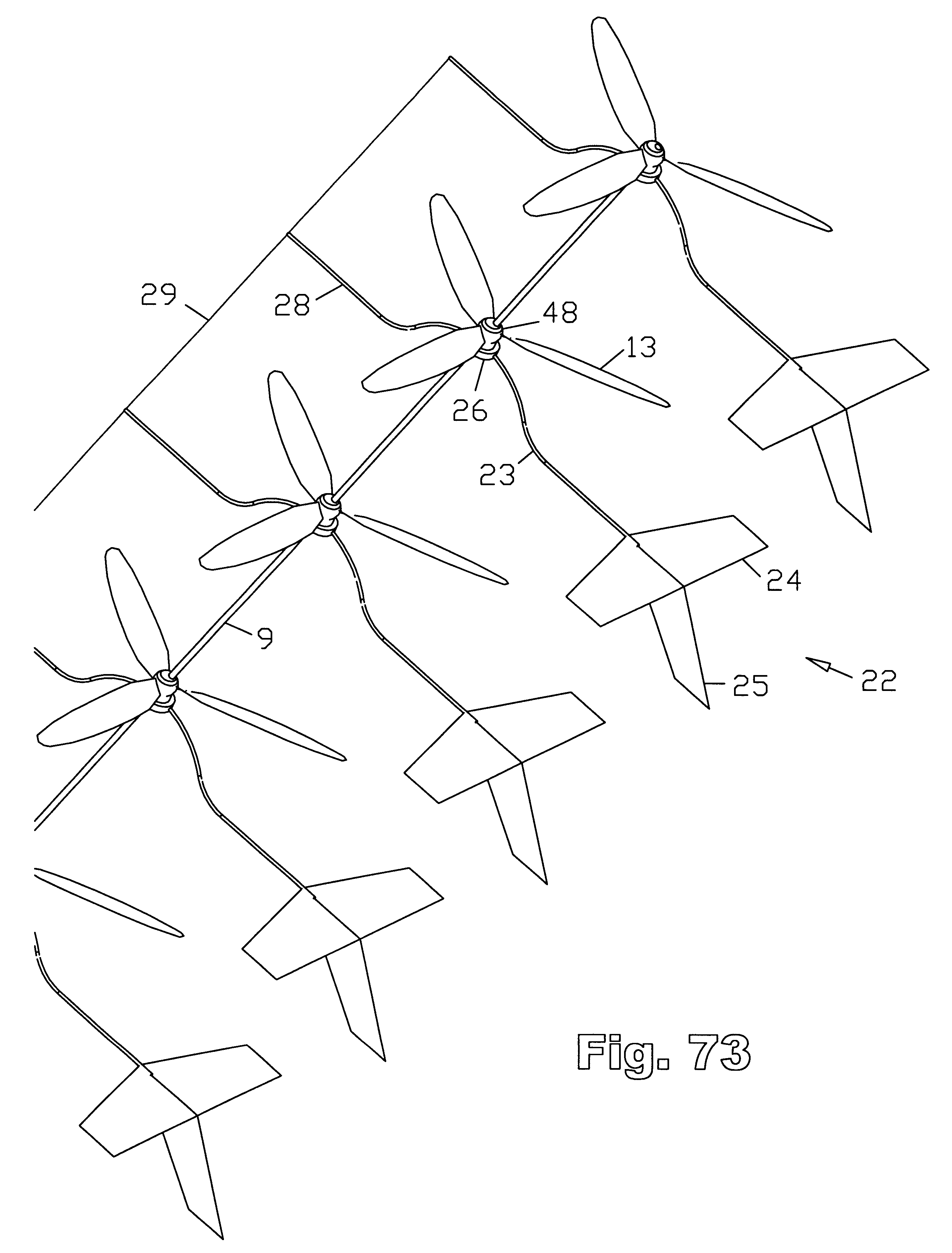
The catenary sag effect as the shaft length increases could be mitigated or even eliminated if each rotor had its own lift. This could perhaps be achieved with blades filled with helium or hydrogen, like on the figure 88 of US6616402 (SuperTurbine ™):
Hi Pierre: It looks like it took you 14 years to figure out that driveshaft sag, or the sag of any rope or chain, in general, has a catenary shape. Yes, that is the official name for the shape of sag. This is mentioned in my patents, for example:
“These three aiming strategies—horizontal offset, vertical offset, and sagging catenary suspension, may also be combined to arrive at intermediate configurations. The idea is to have the most wind possible hit the majority of the rotors of the series, at the best angle for optimum power generation, as much of the time as possible.”
Anyway. of course any sag will have a shape, any shape will have a name, and of course these are the types of factors that need to be accommodated in any design. The absolutist cube/square “constaints” envisoned for ST by Santos represent, firstly, the same cube/square effects that affect all structures, and all wind energy devices, and which indeed form the basis of why we would use multiple smaller rotors as opposed to a single larger rotor, as explained in the patents. So not only did we notice the effect, it is the basis of the design, which is delineated in the patents, so, again, it is old news, or, really, not news at all. Whether you are designing a wind turbine, a truck, or a space-ship, of course the cube-square effects.are always paramount in any design process, not something unique to SuperTurbine™, and not some “new” discovery by Santos.
The entire wind energy industry operates on torque, and always has.
Personally, I never saw the need to even mention the word “torque” it is so obvious.
A major reason why the Superturbine™ concept is compelling is the fact that it utilizes the existing and well-proven formula for how to successfully extract electricity from a wind flow, rather than trying to reinvent the wheel. Instead it just uses more “wheels”.
It’s not too hard to identify instances of other wannabe ways to do AWE beginning down the road of transition to SuperTurbine™. Take Makani for example. They started out flying a figure-8, then switched to a circular path. That was a first baby-step toward becoming an ST, but they gave up after that. It’s OK, like Altaeros, at least they disproved their exact approach. That’s a start.
Hi Doug: this is wrong, flexible AWES are less affected than rigid AWES. The mass scaling exponents K of flexible AWES are lesser than the ones of rigid AWES. This has been well documented for at least 14 years, and not only by Dave Santos. Please specify how many more years it will take you to understand this.
The difference between K = 2.273 and even the lowest value for studied rigid kites K = 2.7, is quite huge, above all if you consider that far lighter flexible kites could start the range at a far lower weight level than comparable rigid kites, ending still far lower.
It is not only an issue of “to have the most wind possible hit the majority of the rotors of the series”.
As I mentioned, the catenary sag effect aggravates the scalability problem. And apparently the problem of scalability due to the catenary sag effect has not been addressed until now: this is evidenced by the skeptical reactions since here, in spite of the details I provided.
I have provided you with elements that allow you to understand why your ST hangs in the middle when it is a little too long, while the altitude is only a few meters above the ground, as shown on this video. If you want ST scales still more, it will look like a large snake that has swallowed a too big prey, napping on the floor, the lifter kite lifting only its nose.
Pierre, you have a good handle on some scaling parameters. Every ST I have ever built or even just sketched has to deal with driveshaft sag. It has been a major part of every machine I build, from day one. It has nothing to do with your recent attention to the matter. The more significant engineering challenges in crafting functional ST machines involves effects that nobody in any chat group has ever identified, and of which I became aware only through rigorous high-speed testing-to-destruction. I have never been inclined to get into a Santos debate over soft kites versus hard blades. As you know, the original ST patent includes soft blades as a well as rigid blades. If anyone has a wind energy solution that works, hard or soft, more power to them. Early wind turbines tended to use soft blades, more modern ones use hard blades. There are reasons. The choice depends on the situation. None of this is new information for me. SuperTurbine™ is a broad concept, extending far beyond airborne versions, and the few versions you have seen do not represent more than a teeny sampling of the vast possibilities. Hypothesized limitations do not take into account the many ways of addressing such supposed limitations.
I also have a lot of other approaches, not limited to either ST or AWE. Anyway, in engineering school, the cube/square laws are emphasized in the first year, and everyone knows about it.
I mentioned the catenary sag effect (which can also be seen as a variant of leverage) on SuperTurbine (tm) and Serpentine, and other torque transfer systems - #35 by PierreB. This leads to a sort of cantilever effect applying to the middle which has no support. Indeed, one end is the anchor point where the PTO is located, and the other point is held by the lifting kite. The other sort of SuperTurbine ™ with a central tower (Twin for example) also undergoes a cantilever effect, but it applies at the ends instead of the middle.
It is the opposite. So I put again the link of the calculator and the example:
Sag is 10x when the cable (or the driveshaft) length is 10x, all other things being equal. Don’t forget to keep the same global weight for the cable in order to obtain a correct result, as I already specified.
The longer the shaft, the more it hangs in the middle.
This has three effects which are aggravated by interaction; scaling problem, losses and stresses in the transmission by induced oscillations.
For the moment I see no other solution, if it is really a solution, than to assign a lift to each of the rotors, as shown in figure 88.
As I see it, there are three competing effects in power generation of a catenary system like Skyserpent. As you progress up the catenary, these three effects change.
At higher altitudes you have stronger wind, hence more power.
At higher altitudes, due to the changing slope of the catenary, cosine cubed losses increase hence less power.
As you progress up the catenary, the masking effects of adjacent turbines becomes less severe and so power increases.
I feel that the cosine cubed losses predominate. For example, increasing a shaft angle from 30 deg to 45 deg will result in a 45.5% loss in power. (Check my math!)
The rotors do not generate lift by themselves, but by the lifting kite which ensures their angle of attack (which is lower (= more lift and less power) for the rotors close to the kite) and the average angle of elevation. The higher the angle of elevation, the larger the lifting kite area.
Also it is not so easy to obtain rotors ensuring both torque and lift. So perhaps rotors ensuring torque and power should be settled close to the ground station, and rotors ensuring lift close to the kite.
If you really want harness altitude winds for power, then only the lifting kite is used, which incorporates a yo-yo system in aligned or crosswind flight.