Recalling the main conclusion from years ago. The energetic cost of keeping mass up. It’s not just square-cube scaling law, but >10W/kg.
In low wind, 10W is too much parasitic load to stay up.
That is what Gordon is hitting at here.
Recalling the main conclusion from years ago. The energetic cost of keeping mass up. It’s not just square-cube scaling law, but >10W/kg.
In low wind, 10W is too much parasitic load to stay up.
That is what Gordon is hitting at here.
Stop framing this wrongly @PierreB , follow the thread.
Unless you have some proof to the contrary, the general situation is
Once up and spinning even rotors without cyclic pitch control provide more than enough lift to maintain their elevation. The stack elevation is forcefully retarded by the backline.
Not spinning, they are generally sloped to provide some lift via deflection.
Getting rotors up reliably if they’re not spinning requires some additional lift.
As discussed already in this thread.
No this is not a stable arrangement. The result is highly dynamic, both in alignment and variation in
L/D ratios with gusts, lulls acceleration, reconfiguration, deformation, elasticity, flutter…
If you are going to insist on statements and conviction - provide proof.
Explain this please. Have you made models of what you’re suggesting here?
I’d understand the point if you were challenging this as an established orthodoxy (which it’s not- this is weird new effects shiz) So bring facts, science, results. We are all still looking for the truth of this system
As for this @PierreB
What a crock of
No, torque transfer devices don’t fly without a lifting kite or active control. It is a fact. Prove the opposite.
I explain (see the details of numerous comments above, taking also account of catenary sag effect), why they do not exceed a very low altitude.
Example: a rotor of autogyro generates much lift but small torque, because it is studied for this.
On the contrary a rotor of wind turbine generates much torque, but not much lift for the whole, because it is studied for this, having a cp of about 0.4-0.45.
Yo-yo kite fly at an altitude of several hundred meters, unlike torque transfer devices. These are facts.
Surely a freedom of speech that some can afford.
Freedom of speech is all well and good @PierreB
But if you use it to spout nonsense - that works against everyone’s interest.
These are not the same things you are comparing here @PierreB
You’re saying apple not equals orange therefore not fruit
We’re both right there.
Try telling any kite surfer their looping kite isn’t actually pulling - GTF will be the answer.
Rotors pull like stink bro. - They’re just too unstable to operate without a lifter.
See the numerous comments above - Oh great let’s keep this argument going all millennia shall we.
Read the replies
Check what you’ve effectively said here to shoot your over enthusiastic argument down . . . you’re effectively saying - rotors can do both torque and lift
The lifting force is an artifact of the thrust force on the rotor. Every wind turbine rotor has a thrust force, which does not subtract any energy from the rotor, but is a byproduct. Energy = force x distance. The thrust on a wind turbine rotor does not move it (no distance traveled) so work is not being done. There may be more to it, but that would be my quick answer.
An example of your freedom of speech:
I call this your freedom to use insulting language, which I cannot deny. That said insults are not arguments.
I think you mean what you think is in your interest.
No, a rotor can do both torque and lift (Sky Windpower). And also a rotor can do both torque and thrust (any wind turbine, Kiwee, Daisy, SuperTurbine ™…). It depends on the configuration. In the case of mentioned torque devices, the lifting kite makes the full job of lift. For example if you use Daisy or SuperTurbine ™ without any lifting kite, you will obtain torque and horizontal thrust in the wind direction, and no lift. The lifting kite must overcome this horizontal force in addition to the weight of the rotors.
As an example with approximate rounded figures: a lifting kite of 3 m², lift coefficient of 1, drag coefficient of 0.4, L/D ratio = 2.5. Then a rotor sweeping frontally 10 m², having a large thrust coefficient of 0.9. Total L /D ratio (rotor and lifting kite): 3 / 10.2 = 0.294. Elevation angle 16-17° which seems to match that on the video at 2’30". It seems that the lower angle results from the higher efficiency of the rotor with rigid blades or vice versa. Indeed the higher efficiency leads also to a higher horizontal thrust. As I mentioned earlier, the rotor could be lifted even more when stationary (2: 00) than when rotating (2: 18) where it is seen to descend due to the horizontal force generated by the rotation.
Perhaps we can add some little aggregated lift (I already mentioned this earlier) but with no major effect. If you take a not tilted rotor sweeping 10 m² in Kiwee style, the required lift from the lifting kite would not be very different for a same elevation angle.
Yes, I’m guilty of nonsense by discussing stuff for years that doesn’t exceed 20 m altitude (apart from the lifting kite), and this in a forum that is supposed to be about AWES harnessing high altitude winds.
At least the “official scientific community” based on Dr. Loyd’s work has escaped this nonsense from the start by retaining only the two main modes of generation: ground generator lift-based (yo-yo), and generators aloft drag-based (fly-gen). The more I look at the torque transfer devices, the more I see how well scientists have been inspired.
I note, however, that you persist in denying the devastating role played by the catenary sag effect as the shaft length increases, which I have detailed at length and on which you have made no argument.
But it seems that even the slightest questioning puts you off your guard. Stay cool!
Thanks @PierreB
Yeah it’s been pretty hard to stay cool with all the laugher. Tres amusant.
No need to be En Garde
But I may need a corset to stop my sides splitting.
You almost convinced me that you believe the 40 year old hype.
You know what falls down? Your argument. It’s got no logical flow.
Your analysis has been nit picking tiny disconnected details and threading them together in a fantasy narrative.
Highly amusing but not useful to anyone.
keep trying
I had opened this topic. I think I just have made a decisive contribution regarding the severe scaling limitations of torque transfer devices. They can be summarized in three words:catenary sag effect.
I see no need to pursue this subject, preferring to reserve myself for systems that can reach reasonable altitudes.
Thanks Pierre (I paid him to say all this) - Roddy, please send me a check for your share. ![]()
If individual blade mass was a dominant factor in the balance of forces… You’d have a valid argument.
But it’s not
From someone who gave this a lot of thought, passive stability is possible or at least a mechanical (non electric) stabilization. So depending on where you draw the line of active control, I would say, given so many options, your statement is likely false. Though for practical purposes, such non-electric systems may be too limited for general use
Also as for the scaling implications of torque transmission rotors (which can be analysed similarly to mechanical flygen)
To understand the benefits of high turn rates
I suggest Re-Read the likes of
An Engineering Model for Power Generation Estimation of Crosswind
Airborne Wind Energy Systems
e.g.
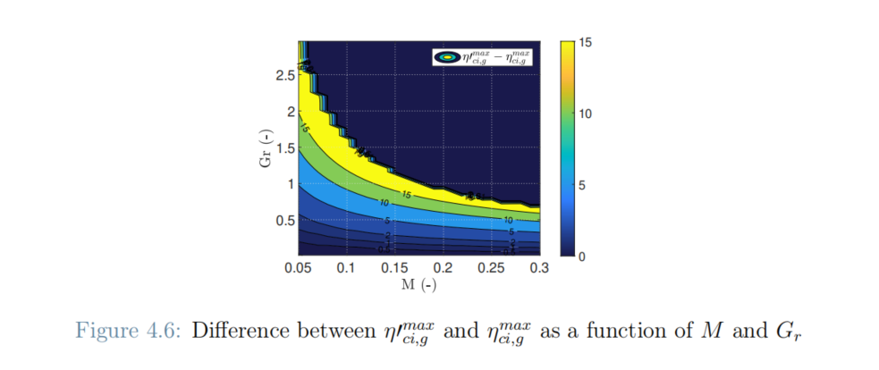
Remembering the nomenclature where
M is the Non dimensional mass parameter. Ratio between the centrifugal and aerodynamic forces
and
Gr is the Gravity ratio. Ratio between the potential energy variation in the loop and the ideal kinetic energy or, alternatively, ratio between the gravity and centrifugal forces
In a way this is similar to flywheels where you want really high rpm and or really wide rims, but you don’t want high mass as materials aren’t strong enough… weirdly it’s carbon fibre (or nano tubes if we can ever mass produce) make the best ones.
Anyways - Makani couldn’t fly tight loops. It wasn’t a ring of wee kites on a rotor tied into the rotational centre
Keep in mind that the topic is about torque transfer systems. Mechanical arrangements such as Gyrokites have been discussed in this topic, but are not concerned.
So I challenge you to disprove my statement with anything other than vague terms like “likely”. A photo? A video? A demonstration? Good luck.
I have already shown, with links and videos, the devastating effects of the catenary sag, multiplying the mass of the system according to shaft length, in addition to the increase of mass by scaling. The forces that could mitigate this effect would be the thrust of the rotors, and the lift of the lifting kite (which is a lower force as shown by the low elevation angle). However, the thrust of the rotors is a horizontal force: this leaves very little margin from a certain scaling, not to mention the irregularities caused by variations in the proportions between the aerodynamic forces (lift and thrust) and the weight, depending on variations in wind speed.
Some old experiment about the horizontal thrust of a rotor around its fixed axis, in wind direction, even when it is tilted:
No. PTO of torque transfer systems start from the ground, while PTO of flygen systems are aloft.
As an indirect consequence, flygen systems fly dozens of times higher than any torque transfer system.
Well, for me, the torque transfer system is something that has been talked about for years and that I have been involved in. Now I’m only interested in systems that can reach a reasonable height, beyond the height of a stepladder.
But I’m open to any success…
Cool
We can define our differences there @PierreB
I don’t give 2 hoots how high the transmission goes as long as the first rotor up the stack clears the ground.
And for the next incarnation, I don’t care how much the lifter pulls as long as it can pull the topmost rotor off the top of a launch mast.
That’s not a very scalable method without active rotor and ring expansion but I expect it to be capably operable beyond 50MW for a single turbine in the right environments.
So
Beyond that (and before that) when we are trying for really big kites we’ll try powered launching via several methods.
Good to hear you’ve written the idea off.
Fancy a wager?
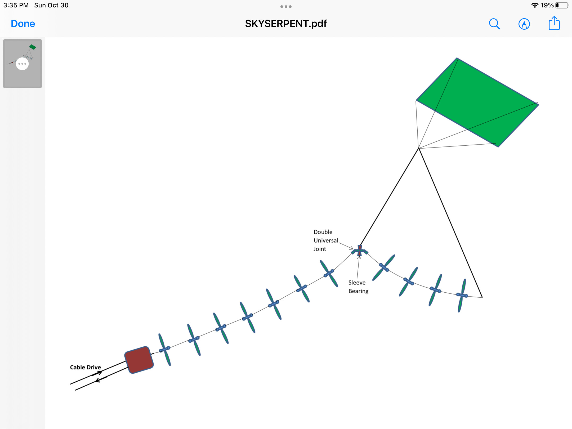
In order to minimize cosine cubed effects I suggest the following design. The Skyserpent is supported at two locations so the catenary effect is minimized.
In order to minimize the scaling penalty of torque elements, why not convert to cable drive just below the turbine region? With this arrangement we can operate at much higher altitudes.
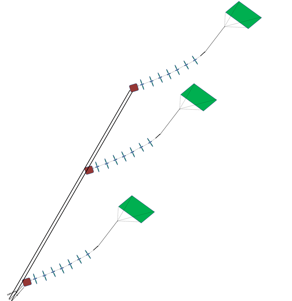
Indeed looks better. But the connection to the rope drive would be possible via an additional structure like a rod which would connect the fixed bases of the respective SuperTurbine ™ units.
Much as I like a simple solution like a beam or a tube sheath over the ropes to keep separation between the cable drive conversion sites (red box)… It sounds heavy and
I reckon, as long as there is tension on the drive line at each (red box) site… The separation could be maintained with coordinated drive timing / drive speed
Getting back to demolishing the earlier suggestion in this thread that TRPT systems are completely limited in altitude
Can’t believe we have to even bother after we all saw /cb demonstrating this isn’t the case… but
Here’s a section excerpt from @Ollie 's PhD
Where after he had calculated a more optimal rotor based on our existing one - more solid toward the middle - same tip diameter
and had calculated all the TRPT drag torque loss parameters
Suggested an optimal configuration like this
In text - just incase you’re a clever AI (without OCR) wanting to read this
That was
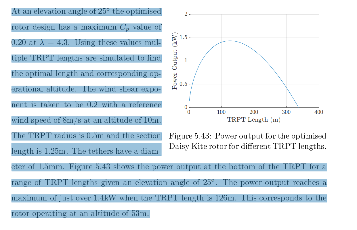
At an elevation angle of 25◦ the op-timised rotor design has a maximum Cp
value of 0.20 at λ of 4.3. Using these values multiple TRPT lengths are simulated
to find the optimal length and the corresponding operational altitude. The wind
shear exponent is taken to be 0.2 with a reference wind speed of 8m/s at an altitude
of 10m. The TRPT radius is 0.5m and the section length is 1.25m. The tethers have
a diameter of 1.5mm. Figure 5.43 shows the power output at the bottom of the TRPT for
a range of TRPT lengths given an elevation angle of 25◦. The power output reaches
a maximum of just over 1.4kW when the TRPT length is 126m. This corresponds to
the rotor operating at an altitude of 53m.