Hi. Just sharing some stuff I have been up to last few days.
I wanted to make a TRPT test rig to test some things related to TRPT
- Effect of varying geometries and tension compared to calculations
- The ability to transfer power according to calculations from motor to generator
- The effect of tether drag
Before explaining more, the results of the experiment were not so good
- I was not able to run at 3500 RPM as needed for a 1:1 scaled down rig
- Friction and electrical losses in the motors was very large, especially as the RPM was much lower than their rated best speed
- It was quite difficult to start the rig without the tether tangling in the middle
- The hanging part was already a bit too heavy by itself, so adding weights did not make sense
trpt_rig.pdf (49.1 KB)
test_runs.pdf (2.4 MB)
3 Likes
Wow 3500 rpm is very fast.
Are you able to use a slow ramp up to that speed on the motors? Some motor controllers use field oriented control which often let’s you do very slow speeds using the hall sensors without an encoder.
Yeah I could add a computer to the mix. Though Im not sure if the effort is worth it
So, is the reason for the 3500rpm - to match the speed through the air which these lines would fly on a larger rig of a certain size?
So that you can measure line drag?
1 Like
Yes. Lately I am reducing RPM because my rig cant handle 3500 RPM. Then I need to compensate by increasing the tether diameter. I am getting some good readings now
2 Likes
Why not run the system with a rigid rod between the motor and generator to get a baseline efficiency?
3 Likes
Doh. Why didnt I think of that.
1 Like
All roads lead to SuperTurbine™ 
Roads do not fly!
Finally I don’t know about TRPT roads.
To be serious if possible, the achievable height of rotary torque transfer AWES remains a question.
No. I have calculated that length of the shaft is not a limitation, considering some prerequisites, the most important being a high efficiency kite layer(s) at one end
The length is limited though compared to other structures, but I dont think long tethers are so useful anyway due to the drag they create
1 Like
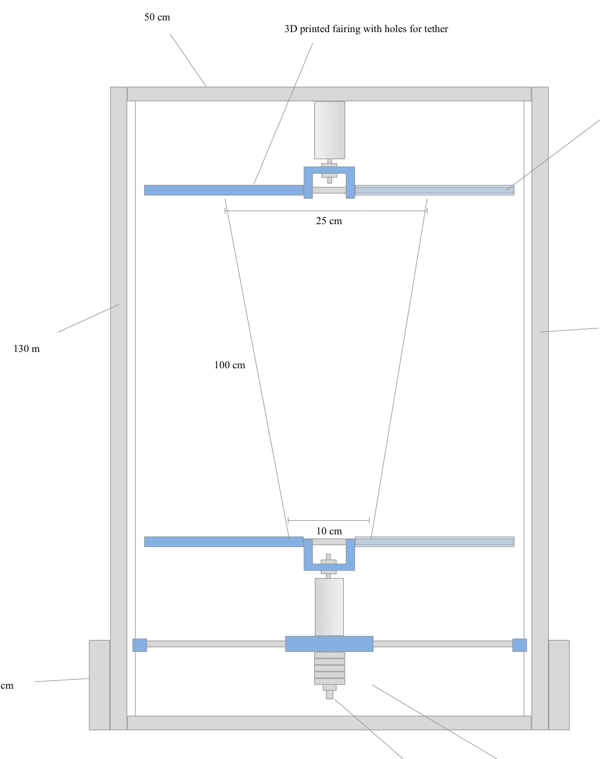
Small update. Today I measured tether drag and tether “belly” (bending due to centrifugal forces on tether). I think this is a reasonably scaled model of a rig that could have been hundreds of meter long shaft.
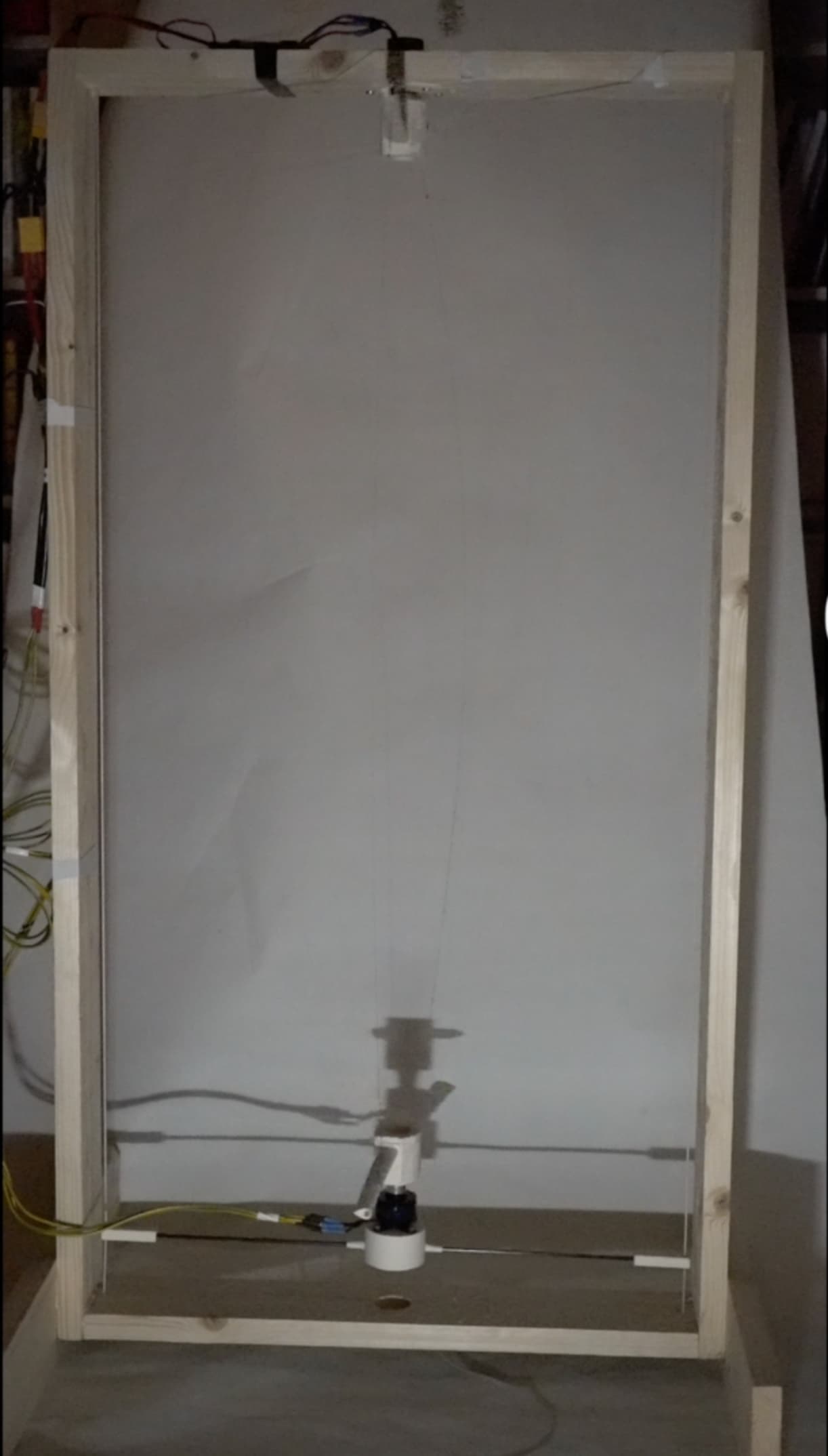
In this picture you can se the tether drag shown as a “splay” angle between the two tethers at top and bottom.
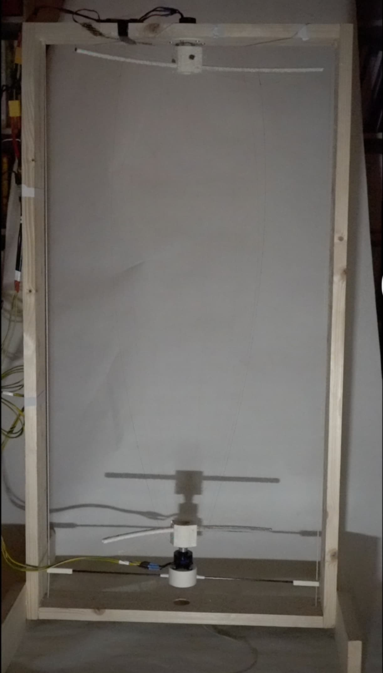
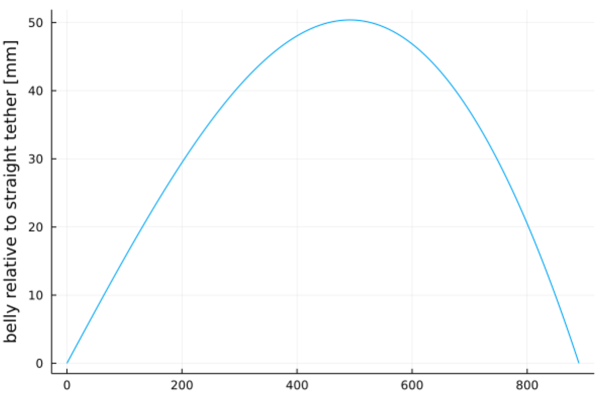
In this picture, you can see the “belly” shape.
Here is my estimated “belly” size, 5 cm on either side. My graphical solution from the photo gives me 4.5 cm!
Cool stuff.
2 Likes
Can you share those calculations? I’m not inclined to trust that result. I would think that lower torsional stiffness and flexural stiffness, and here also line drag, would contribute to a certain loss of efficiency per unit of length so that after a certain length of shaft, no torque could be transmitted. There’s some discussion on that in some of the comments under this video IIRC.
In looking for this I came across this flexible rotary shaft: Flexible rotary shaft operation, uses, and advances | Machine Design
And this appears to be what I am talking about: https://www.mathworks.com/help/physmod/sdl/ref/flexibleshaft.html
internal material damping
I guess the underlying question I have is what effect phenomena like internal material damping, torsional stiffness and flexural stiffness have on shaft efficiency, or TRPT efficiency, per unit of length. Your source doesn’t seem to address that. I haven’t looked at the book chapter.
Nice work btw.
In my message I defined the limitation of the length of the torque transfer shaft as a question (see above). But it may be that I was below reality, as shown by the analysis of the rotating reel system which is a TRPT AWES. The Fig. 22.18 reproduced below summarizes said limitation:
https://www.researchgate.net/publication/324135034_Airborne_Wind_Energy_Conversion_Using_a_Rotating_Reel_System
The limitation is severe.
Of course it is a bit different for TRPT like Daisy because both ground and flying rotors are parallel unlike those of rotating reel. As a result the shaft length / rotor diameter ratio will be higher than for rotating reel system, before still increase by the rigid torque rings.
We speak about a single rotor. A stack of rotors could probably push the limit further for both systems (with always an advantage for the Daisy-like system).
So much for a few points of theory. Now in practice please let me know when TRPT or other torque transfer installations exceed say 20 meters in height: I haven’t seen anything like this for years now.
And I think that the possible height is a fundamental parameter to reach high altitude winds which justified the research on the AWES (see the work of C. Archer). Competing with HAWT at low altitude is a decoy.
What will be presented in AWEC2021 is that the shape presented in this test rig is fully scalable except cubic mass. So a large windmill with a soft shaft exactly like the one shown in the test rig should be feasible as long as mass/gravity doesnt take over altogether. The two shafts of similar shape will have the same \Lambda value, a non dimensional number to describe a soft shaft (or a shaft of multiple segments) has an ability to transfer moment without collapsing.
The tether shape above should be good for a Makani/Ampyx/Kitemill type of «plite» with a wingspan of around 6 cm. Now multiply every dinension by 40 and you are in the MW scale. That also includes multiplying the tether diameter.
If you do that and make it rotate at the same kite forward speed as the rig, the tether shape should also be the same.
I think it would not be hard to visualize the above shape tilted at an elevation angle 25-35 degeees, on a short tower to allow space for the bottom rotor to rotate without touching ground.
I will share details shortly. I find this direction of AWE very promising so far though.
2 Likes
The number they are referring to \Lambda = \frac{M}{T R} need not be higher than 0.05 or even less with an efficient kite. Then please redo your conclusions about length…
1 Like
Yes the limitation is severe. The Fig. 22.18 I attached confirms this.
Please read this before comment.
If you want to scale without having to install rigid elements (which will scale badly) the only possibility is to scale the diameter of the flying rotor, but in this case you will have a gigantic tilted ground station.
I have read and fully understand what is involved here. Your chapter describe systems with glide number well below 1.5 it seems. It doesn’t make any sense in my scenario where the kite and tether form an aerodynamically efficient high glide number >8 system. If that is the case, the limitation in shaft length largely disappears.
I’m sorry to say your chapter in the AWE strikes close to gold, but really misses the boat due to these design choices.
1 Like
@Windy_Skies
None of those links seems relevant.
There were >900 comments on the Doug Selsam superturbine video — If one of them is relevant , and again I can’t see how because it’s a rigid shaft they’re describing…
1 Like