There is no internal material… The internal is a hollow, A void, A gap between the rotating tethers
Ollie addressed that in his thesis as did much of my TRPT analysis
A good representation of torsion in inflated beams is found in “An Engineering Methodology for Kite Design” By Jeroen BREUKELS… But again it’s an inflated beam… Quite different
I just read this and it would make sense to me that if you had high glide numbers in mind when writing this, maybe you would make a point that the glide ratio mostly by itself determines the length of the soft shaft…
I will not say that you had not considered this, but reading the text I have the feeling you are moving in a different direction in the book relative to my starting point here.
Also then you would maybe not have the need to insist my idea is infeasible when in fact it makes perfect sense…
I will make a simple argument: double the glide number, and the flying speed doubles for everything else the same. This also means the pull on the tether quadruples. Take a doubling of \omega and quadrupling of T, the moment-to-radius-to-tension ratio \Lambda need is reduced by a factor of eight…. thus the shaft can be a lot longer
Lack of evidence isn’t due to lack of truth, it’s lack of testing if anything. Why aren’t more people testing this? is a much more prescient question!
You did see the repeating element lengths of the TRPT flown by /cb It works.
Being determined to scale purely the transmission length elements of TRPT at the expense of mass and drag is a decoy.
Multi layered TRPT rotor elements which add to the overall tension and torsional rigidity as per the models I ran… That is worth looking into.
Let’s say we make a turbine only 10m taller than a standard 3 blade wind turbine… But it’s 60% cheaper over the lifetime and 20% more energy out for 20% of the initial embodied energy… Hell yes that’d be worth it. Wind exists all the way up.
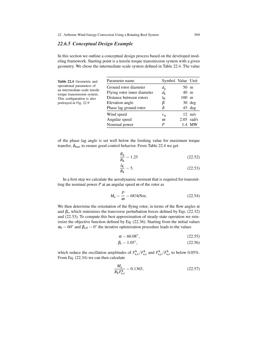
The table 22.2 you refer is a part of the 22.4.2 Experimental Results .
The material realization of a rotating reel system is not easy, and I made it with what I had on hand. It is easy to understand that this realization was not optimized. If no, reading the chapter is sufficient. Page 11:
The efficiency of the flying rotor was not measured, but as it uses numerous semi-rigid blades forming a high-solidity rotor the efficiency is considered to be far below the value of the Betz limit.
I dont think making me read all that makes much of a difference. Rather just explain why you are knsisting in these high values \Lambda = 0.1365 when 0.05 would do the trick… and with a 2.5x shaft length…
By that do you mean the question about efficiency per unit length of TRPT shafts I put above? Do you have links to sources, and preferably page numbers?
A coefficient of reduction of the transmissible torque as a function of the length of the shaft is also necessary. See on this subject figure 22.18 already commented.
Please can you link the reference?
So far the references you have provided about my chapter have not supported your statements because they were not contextualized as I mentioned above.
« If the rotors are many diameters apart the tether system can not be used effectively for torque transmission.»
I would think this is untrue for many valid configurations. Already my rig is using 4x and 10x diameter tether length and transmitting power. Actual power as reported by the VESC, and in full accordance with my calculations.
From here on the paper is describing a rig that is just so different to what I was sharing, that the two are not really comparable. So I suggest you talk in terms of using concrete words rather than directing me to your text again. For discussing the chapter in the AWE book I believe a thread already exists where I already shared my opinions.
It is quite true for the configuration which is studied in the chapter. As I mentioned the rotating reel system has less range because the flying rotor is tilted relative to the ground rotor which is horizontal; and parallel rotors (Daisy or similar style) will have a far higher tether length to rotor diameter potential ratio, possibly 4 x as you mention.
I experimented turning an horizontal 0.8 m diameter ground ring with another 0.8 m ring and 2 m tether length between them: that worked well while if the second ring was tilted (rotating reel configuration) it did not work, or worked when the two rings were closer each other.
This is the case with being reasonably optimistic. Do not exceed 20 meters in height regardless of the torque transfer system studied, and this for years, confirms the validity of my question. Even if valid configurations could work in simplified analysis, problems can occur in practical situations or in detailed analysis.
Wishing you a successful AWEC2021 presentation of the concept.
Indeed 10x (the distance between the two tethers on the ground rotor) is what we see on your initial post and also likely on achievements.
Some suggestion: I think you need a tensioner device for the tethers. This device could be (two) winches settled on the ground rotor (generator) and allow to vary the tether length between the two rotors in order to stretch them. At the same time the tensioner device can allow measurements according to the variations of the axial force (more or less that generated by the lifter kite).
In my opinion in the kite field autogyro-like rotors have a higher tangential speed (tip speed ratio TSR) than other kites and would facilitate a first realization of a physical flying (with a lifter kite or a slew plate for cyclic pitch control) model: two tethers, two blades. That said the use of two controlled separate kites could facilitate scaling.
I am using the mass for tensioning. This is quite difficult to build because you want perfect control of the shaft tension and at the same time the tether length should be allowed to change freely. The way I solved it, with the hanging weight works ok, and actually at this scale the tension is so small that the motor and the few supporting parts to hold it actually weigh a little more than the tension I want.
I can of course increase the tension easily by adding weights.
Of course the tension is only guaranteed when the bottom generator/motor is not moving up and down.
The setup as shown actually works quite well once running at a stable condition. And already giving many results to support calculations done prior to this.
Also consider the conplexity of the build. Right now I just have a motor with ESC connected to a radio. Then there is the other motor connected to a vesc and then my computer. A camera measures the tether twist. Very simple. Adding a new mechanism would have to be very simple if I was to be able to build it in a similar timeframe to what I am seeing here.
Also please comment on why you think the tensioner would be useful, I am curious about that
I must say @PierreB that you are coming cross somewhat grumpy to me right now and there is no reason. I did read your reply in full. I also read your AWE book chapter a few times now in full. I do understand. The discussions goes on and it seems to me sometimes the message is now coming across clearly between us. So please just be patient. I do really appreciate your involvement and feedback, and also the stuff you are submitting of your own.
At this point in time there is much more text to be read than anyone in AWE can absorb. So one must appreciate that most people have not and will not read all things written. So the fact that I have actually read your piece several times now is something that you should not expect most people to do.
And to be honest I think there is no good reason that everyone must read the chapter in the AWE book. Because you guys seem to have come to a dead end, something that your comments here have maybe confirmed. When there was still a lot of potential in TRPT without rigid supports, that was not mentioned in the AWE book, and that I am trying to point out here.
Maybe rather keep an open mind and move forward. Maybe make or revive a thread about the original AWE book chapter if you want to have a second round of dicussing that
However you choose to take a reference of the chapter which cannot illustrate what you wanted to demonstrate because of the reasons I quoted (tip speed limit of ≈ *70 m/s). The requirement of a high TSR to achieve high efficiency is already in the chapter.
Basically you are talking about a TRPT with parallel rotors and without rigid supports. This option is obvious. And I agree that scaling with torque rings is difficult. In the other hand these rings help to increase tether length / rotor diameter ratio.
That speed at 12 m/s and 30 degrees elevation suggest a TSR around 6.5. At this TSR I cant explain why you came to the conclusion you did. Though I would like to go even higher in glide number, i suggested >8. The tether is maybe the limiting factor due to the drag and «belly» shape. Though the AWE book does not seem to go into this in detail. The explanation is made very complicated by the angle between the rotating parts and the pulley system.
Also, I dont really understand the plot which seems very core. Please explain if you like
All is in the figure 22.18. This figure shows that, even with a high TSR, the limitation is severe, at least concerning the rotating reel system.
You cannot quote my chapter in order to support what you believe demonstrate and invoke the requirement of a new thread in the same time. Subjects about TRPT have some connections although also some differences.
You seem to have missed that the TSR or glide number is defining the \Lambda value (moment to tension to radius) required of the shaft. I believe the optimum value is
\Lambda_{opt} = \frac{1}{2 \frac{C_L}{C_D} }
That is why a glide number 5 rig only requires \Lambda = 0.1, and even lower values are still feasible without large losses in output power.