A tip speed limit of 70 m/s with a wind speed of 12 m/s suggests a rather high glide number (lift to drag ratio), of over 5.
1 Like
Hi @Windy_Skies
I am sure it was clear I meant Ollies paper addressed torsional rigidity dynamics in TRPT.
As for efficiency in TRPT… Per unit length or otherwise…
Have you identified some losses other than line drag?
Some TRPT configurations significantly reduce line frontal drag area for equivalent kite loops while also providing an easy means to stack kites for even lower overall drag per lift
I have now quickly scanned Ollie’s paper, I don’t see where it addresses variables like those I ask about and especially how they relate to shaft efficiency, which I am curious about in this topic. Good to see some testing was done.
Line drag seems important, yes. Tallak’s second, most important, law about tether scaling too. But in comparing a shaft to the ideal, a totally rigid, short, shaft, things like I mention in my previous comment seem important too, or likely there are other things…
I might be interested in tensile torque transfer (with no or minimal rigid elements), but only if it was able to efficiently transfer torque over hundreds of meters with modest losses, and if I knew what variables I could tweak and what effect that would have.
1 Like
Hi @rschmehl, please could you extrapolate from the figure 22.18 of the now old chapter about RRP, in order to produce even an approximation of the tether length / ground rotor diameter (50 m) ratio for a transferable torque without significant losses, considering that both rotors are parallel (like Daisy, but with only tethers, no rings, or like the model studied by @tallakt in the present topic), keeping the tip speed of 70 m/s with 12 m/s wind speed? Thanks.
Good to hear that you may consider being interested in TRPT eventually when it proves something it doesn’t need to. And that you managed to scan Ollies PhD for something you wanted to find which isn’t relevant nor there.
It’s normal to feel Fear, Uncertainty and Doubt when faced with new concepts.
Just adding a plot to show my findings on soft TRPT shaft length
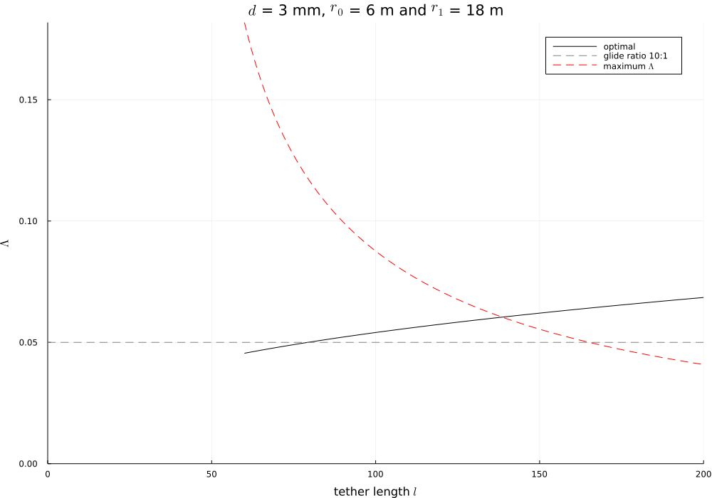
The red dotted line is the maximum \Lambda the shaft can hold, and the black one is the required \Lambda to get optimum power output. The grey dotted line is where the system lift/drag ratio is 10:1.
Note this analysis assumes the kite drag is zero. This is not a bad approximation as long as the kite glide ratio is a bit more than 10:1, perhaps 20:1 is enough that kite drag does not make much of a difference.
Also, as @PierreB says, the limitation of tether length is a bit limited. The kite I have in mind here is 6-8 m wingspan, so that gives us a ratio of 5.5:1 kite radius vs tether length, a little bit more than presented in the AWE book Fig. 22.18, with the plot going from 0 - 5 on the x-axis.
How to read the plot: The black curve is the interesting one. The shorter the tether, the better possible system lift to drag ratio. The better the glide ratio, the less \Lambda value is needed. But you should always be below the red dotted line that represents the maximum possible \Lambda achieveable with the given tether length and radii.
The black curve value of \Lambda is related to system glide ratio by \Lambda = \frac{1}{2 \frac{C_L}{C_D}}
My conclusion is that getting sufficient moment transfer \Lambda is not a problem, rather the tether drag, if you want a high system glide ratio.
Or, some means to limit the tether drag. You have initially the tether fairings and the “trouser” mod I will present later.
2 Likes
I was able to estimate the tether drag coefficient to 1.38. Expected value from the AWE book 2.0 is 1.0 or slightly higher.
If we don’t use the tether drag with “belly” calculations, but rather a straight tether model, the tether drag coefficient is estimated to 2.4. This is much further from the expected value. The tether is rather bent though, in this experiment
It’s encouraging to see single section TRPT on a glide ratio of only 10:1 having such breathing room for reliable performance even at >100m
Wow
A 6m radius ground Station PTO arms seem like a big powerful pieces of equipment.
The figure is lying a little bit as that glide ratio is without kite. With the kite, and having drag allocated evenly at the kite and tether, the glide ratio is going to be 1:5 and the shaft \Lambda will be just sufficient
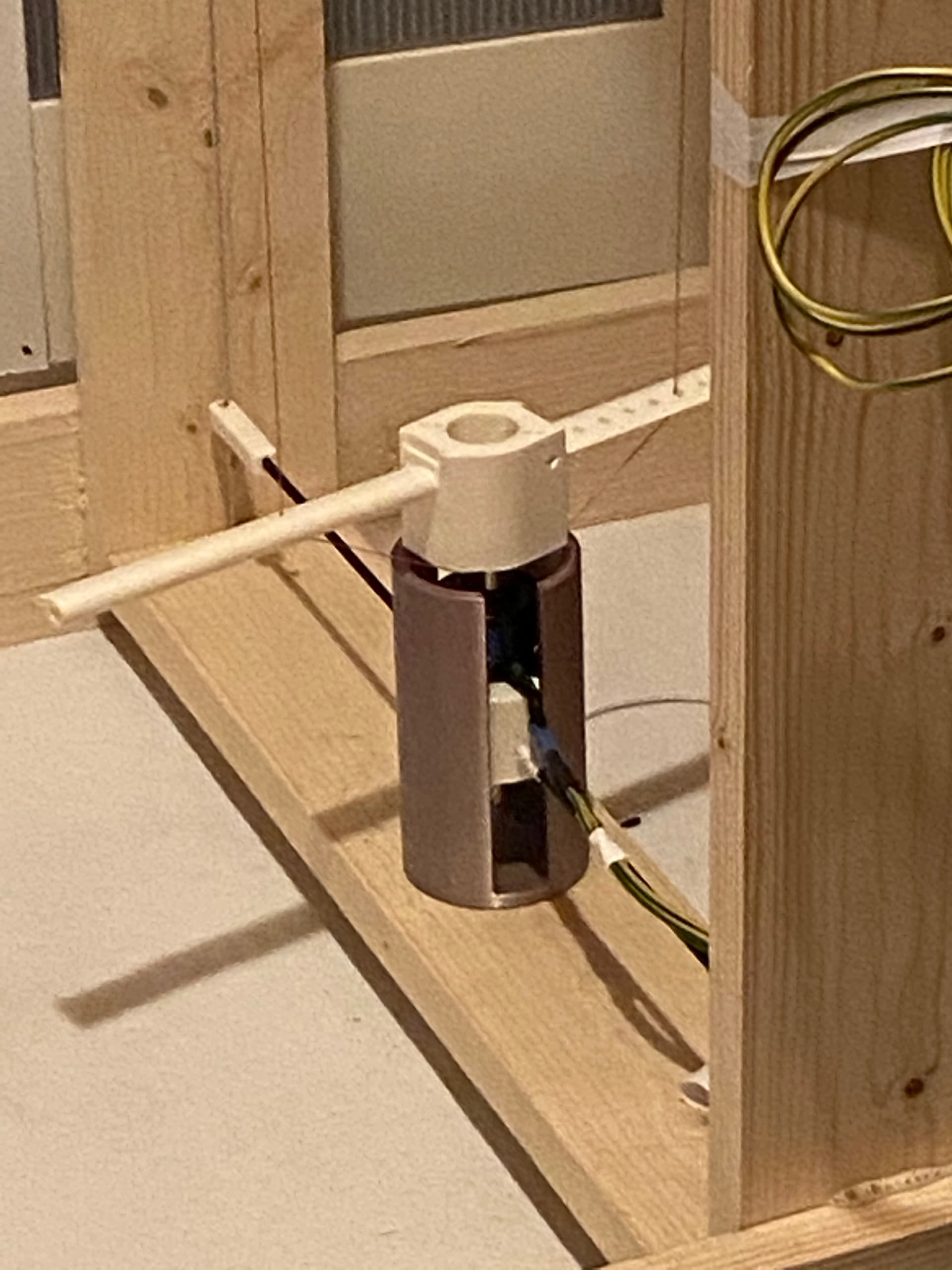
Here is an idea you could test with this setup:
You could perhaps hope to gradually reduce the tension and let the blades take over tensioning the tether. You could test out what effect different configurations have on cone angle, kite and system stability, and so on.
Definitely. That design required wind though, so either a fan or bringing it outside would be in order. Maybe also scale up to make production of blades easier. Definitely doable I think (initially) but quite an undertaking and right now not my project
Perhaps trying two flexible blades in tilted VAWT way, a little like the Flexor system below with only one blade,

but in AWE way, with a (likely huge) lifter kite:
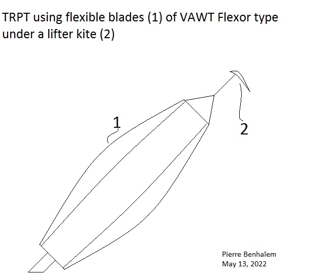
With a (modified?) TRPT Test Rig and a large fan, or outside with a fairly constant wind, maybe a vertical version of this two-bladed VAWT could be tested.
2 Likes
I don’t think it does if you replace the generator with a motor like in your setup. Agree and fair on your other points.
Love it @PierreB
Now we know single line TRPT is viable too. That might actually be capable of driving it.
In the video the flexor was vertical axis… To tilt it you probably want to tilt the leading edge of the “fuselage /boom” down tail up
And cut the sail similarly.
Bet it needs a mighty lifter.
Maybe best arranged across a valley between walls
1 Like