Cyclic pitch control for Rotary Airborne Wind Energy Syst. using a rotation compensating slew plate

Dear all,

I have been quiet for a while - but not lazy :slight_smile: I just published a video of what Team Tueddelpower has been working on for the last couple of month. It is not “airborne” yet - but imho shows great promise so I wanted to share:

Current Rotary Airborne Wind Energy Systems (RAWES) work without an active control system for the rotor using a pilot kite for passive control and lift. The pilot kite method has however limitations for reel in/out systems, automated launching & landing and larger systems.

A cyclic pitch system in the rotor could remove the need for a pilot kite by using the lift generated by the rotor itself and by making the rotor steerable. Combined with collective pitch it would also allow for reel in/out RAWES.

A rotor control system could be implemented using ailerons with servo motors in the rotor blades. The servos doing cyclic movements for each turn of the rotor might however have negative impact on their durability. As an alternative we have chosen a design derived from swash plates used in helicopters.

A swash plate needs to be connected to a rotary stable part of the rotor. In helicopters this is achieved using an airframe with a tail rotor. An airframe and tail rotor less alternative design is to build active rotation compensation into the swash plate. Such an active rotation compensator has been suggested (Moritz Diehl/Lukas Klein: Rotation Compensation for Rotary Kite
Systems) for RAWES to avoid twisting of the primary tether and for providing a rotationally stable attachment point for position sensors (e.g. GPS).

The result of these considerations is the rotation compensator based cyclic pitch control for Rotary Airborne Wind Energy Systems shown in the video in which the position of a swash plate is measured using an IMU and maintained by a small motor that spins the plate against the rotation of the rotor maintaining its position relative to the ground.

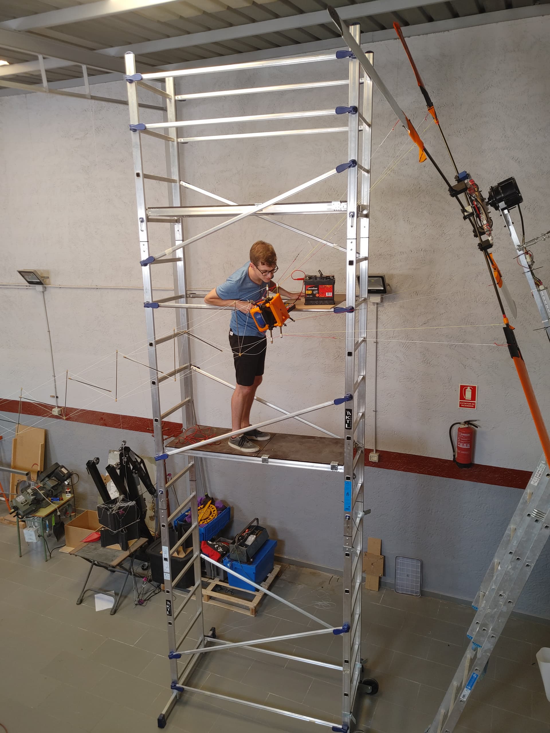
So where are we with our development? In the video you can see a test run in the hangar last week. The rotor on the wall is a mock up with a built-in motor to drive the system. It has built in load cells in all four arms allowing us to log the aerodynamic forces.

We used the test to see if the mechanics actually work, to fine tune the control algorithms and to collect data. Lots of data.

The test was very successful so the next test will be done actually airborne in the field. For that we will have to bring the team together in one place - which due to Covid restrictions might take a couple of weeks. So please be patient - I will publish the most beautiful crashes instantaneously.

The details about the control system and the data itself will be published as part of Daniels Master Thesis this year. As usual all the designs are open source and can be found in my OnShape and in Keith’s Github (see links under recent videos) - let me know if you need any additional information or help building your own version of this.

Thanks to Team Tueddelpower, to our incredibly talented Master Student Daniel and to Moritz Diehl for coming up with the idea of a rotation compensator.

Enjoy!
/cb

6 Likes

Hi Christof, what a progress! Congratulations for this technological advance.

I have a question: the swash plate comprises a central fixed part. Is there something holding it and preventing it from turning?

A fixed part could also allow the implementation of a rope-drive system (Kiwee style)…

Thank you, Pierre :slight_smile:

Since we don’t have a fixed part on the rotor to attach a swash plate to, we measure the movement of the plate with an Inertial measurement unit (IMU) and spin it with a motor against the rotor just fast enough for it to stand still relative to the ground./cb

3 Likes

Gosh That’s impressive!
Really looking forward to seeing test results.
Wishing you all the best winds for that.
Very honoured to have a wee feature moment in this video thanks @/cb

Going to be a nag and ask some questions
What’s the system weight?
Quite significant I’d guess with the battery, IMU, Drive, housing, arms, linkages
Is the intent to scale the device to maintain this function? Or change to individual wings having their own controller at larger scales?
Battery life any good?
Does the system have to be active when the speed or control setting isn’t changing?
Can the mass of battery and motor be used at the bottom of the device to help hold position against rotation and maybe be lightly backdriven for regen inside the controller?

2 Likes

This looks like very good stuff. Actually quite similar to my thoughts about where TRPT rigs may be heading. Cant wait to see it fly!

The design with the battery looks good at least as a starting point. Getting power in there may be a slight challenge. I think this may be solved by a second layer of counter rotating wings in the future. If you do that you should have any amount of power directly accessible from the two shafts. The second layer maybe could be quite a bit smaller compared to the main layer.

2 Likes

Beautiful. Thanks for sharing. Looks impressive.

We are also moving ahead with our collective and cyclic pitch system for our hybrid turbine.

I looking forward to see if fly!

3 Likes

Master Thesis Presentation: Rotation Compensation for Rotary Kite Systems

Lukas Klein

University of Freiburg

Thursday, August 01, 2019, 14:00

Building 102 - SR 01-012

Rotary-kite airborne wind energy systems generate a torque on their ground connecting tether as a side effect. The resulting tether twisting has to be compensated in order to guarantee a durable and stable operation. The active rotation compensator consists of an electric battery, a computation unit, a servo motor, an inertial measurement unit and is attached directly to the rotor axle. On the other side the tether can then be connected to the rotary stable part of the compensator.

In this thesis a general model to describe the system behavior is derived. Two different state estimation algorithms (Complementary filter and Kalman filter) to convert the data from an inertial measurement unit to a rotation estimation are compared. To compensate this rotation a model predictive controller with real time capabilities is described and implemented. A prototype of the system is developed and tested with a rotor-kite emulator. The control algorithm (100 Hz) and the state estimator (250 Hz) run simultaneously on an embedded computer. The prototype is actuated using a speed controlled permanent magnet synchronous motor.

It is shown that the system is capable of compensating the tether rotation by the rotor. Thanks to his self-contained design it is adaptable to similar systems suffering from the same problem such as multi-kite airborne wind energy systems.

This innovation can lead to many improvements for rotary systems.

As “the tether can then be connected to the rotary stable part of the compensator”, perhaps a mini wind turbine could also be connected in order to replace the battery and supply the rotational motor.

1 Like

Great detective work, Pierre. Yes, that is the Master thesis based on Moritz’s idea of a rotation compensator. Trying to find a good first use for it, together we came up with the “slew plate” concept/cb

1 Like

Hey Rod,

Excellent questions :slight_smile:

What’s the system weight?

Ready to fly it clocks in at just under 1kg (994g). I assume I could squeeze out another 100g easily (e.g. we are driving the gimbal motor with a full VESC controller - just because that is what we had at hand and the code ready from the base station) Drone ESCs are significantly lighter.

Quite significant I’d guess with the battery, IMU, Drive, housing, arms, linkages
Is the intent to scale the device to maintain this function?

The intent is to make it work first and optimize&scale up later :slight_smile:

I do want to build a 5kW system faster than you though and race you across Europe in your nissan e-nv 200 - with no plug ins :wink:

Or change to individual wings having their own controller at larger scales?

One of the things I like about the design is that at any time the pitch forces of two blades balance each other out at the plate. That should reduce the power needed by the motor. If you build a system that drives the wings individually I assume your power consumption goes up significantly.

I do not have the quantitative values for the forces needed yet but my “feeling” is that there is plenty of reserve in the current design.

Battery life any good?

We are using a 500mAh 3S Lipo. If my math is right that should give us some 6Wh? We did log and do know the power consumption of the motor. At max speed and max pitch it is <4W according to the VESC API. If we add the micro controller consumption we might assume 6W total which does match our experience that we get about 1h battery life at full speed. Keep in mind that this is at 0m/s wind speed - I assume that the motor consumption goes up when airborne at 10m/s…

Does the system have to be active when the speed or control setting isn’t changing?

As long as you need cyclic pitch the gimbal motor must be spinning the slew plate with rotor speed. The linear actuator that drives the pitch amplitude is self locking and only needs power when moving.

Can the mass of battery and motor be used at the bottom of the device to help hold position against rotation and maybe be lightly backdriven for regen inside the controller?

Well, I wanted a passive design all along (using a pendulum or wind vane etc.) but you know how kids are these days - everything needs a controller :wink: Kidding aside and to be honest we have squeezed everything into the plate without looking at mass distribution. At larger scale and for the future your idea makes perfect sense. One of the things we hope to see in the data is actually where is “the bottom” - does the rotor steer 180deg away from the max pitch or is there an offset? We will see…

Enjoy!
/cb

1 Like

Very nice work. It’s easy to see potential applications for this for similar systems, like the multi-kite airborne wind energy systems mentioned in the thesis. At first glance, torque transfer seems the most difficult application as there every part of the airborne part is originally rotating at the same speed.

1 Like

No! It’s easy - we use sophisticated air-to-air refueling technology:

:wink:

Mean people have suggested that - due to my lack of craftsmanship - everything I build wobbles. Hence a simple energy harvester should produce plenty of power :wink:

Kidding aside - your idea is what we have in mind once we manage to keep this thing airborne long enough for the first battery to run out.

/cb

1 Like

Yes, one of the reasons I committed to this development is the hope that somebody picks it up and builds the first rotary reel in/out system with it. So far torque transfer has worked better than I ever expected and I will stick to it - even continuing to use a lifter kite. This system gives us options when scaling up and for pivoting to reel in/out should we ever hit a road block with torque/cb

2 Likes

This also gives you the option to yaw the rig relative to the wind. So this allow you to put the rig more efficiently on a moving vessel.

2 Likes

Below is the same video, for the picture allowing to see some details:

Dear all,

I thought you might be interested in an update:

First flight of a pitch controlled rotor for airborne wind energy systems

Enjoy!
/cb

3 Likes

I think Q1-2-3 are maybe due to the same effect.

My hunch: when a motor moves sideways, the one side of the rotor is moving slightly into the wind and the other out of. As the blades are already moving very fast, this will translate into a pitching moment as the lift on either side of the rotor changes.

The effect is opposite if the wind direction changes so YMMV.

The book to read about this is Rotary-Wing Aerodynamics (Revised)

In short, if airspeed at each blade is V, sideways airspeed is W and distance between the blades is x, the pitching moment is

\tau = x \frac{1}{2} \rho \left((V+W)^2-(V-W)^2\right) C_L S

Simplified to

\tau = 2 x \rho V W C_L S

The effect should be approximately proportional to your rotary speed.

As you dont know the wind, the only option to control it may be feedback control, maybe by gyros mounted on each blade. I think maybe its no big deal to do this now that you already habe cyclic control of the blades.

The gyro effect would only be seen if eg you rotate in azimuth and the rotor will rotate towards the sky?

3 Likes

A simple experiment would be to control a sine in azimuth then observe the change in elevation angle.

If azimuth is leading in time over elevation, you may implement a solution as feed-forward…

2 Likes

I appreciate that you are sharing your learnings.

We have been using a fixed cyclic pitch system for our wind turbine for the past ~ 6-12 months. This is to reduce the downward moment on the “boom/horizontal axis” created by wind-shear interacting with the rotor.

A couple of weeks ago we tested a new system with active boom angle through actively controlled cyclic pitch (PID). In about 7 days of runtime we experienced to incidents. In both cases I believe a gust caused the turbine to be stalled. In stall the lift slope of the blade changes and hence the control system becomes unstable. This can be seen here .

We also have the cyclic pitch at 0-azimuth. (straight up). As Tallakt mentioned, the gyroscopic effect only comes in to play once the axis of rotation is changing. Don’t think I can answer your other questions, but I think our systems will have similar dynamics.

3 Likes

I think a big difference between the Kite-X rig and the someAWE rig is that the Kite-X rig will not travel a lot crosswind, while this is easier for the “free flying” rotor. This may also have an impact on the magnitude of such effects. Just adding my 2 cents, @aokholm would be the person with actual knowhow here.

Thank you all for your input. I learned a lot :slight_smile: As you can see there is still a bit to learn, but there is progress:

This is the latest test footage. The wind was very unstable and to weak to stay airborne for long times. But you learn a lot in the gusts :wink:

Enjoy!
/cb

3 Likes