I think my comment should be quite conclusive to put serious doubts to the TRPT plus reeling idea. The only thing that matters if you want to withstand torque is the tether length and the two looping radii.
The length is very long and radii very small for the reeling section. So it could never withstand rotary moment necessary to convert rotary power at the upper layers to reeling power.
I could explain more, but unless you somehow give me more details on how this could be solved, I suggest moving on to the next idea.
The problem of the TRPT is in its low part, between the first rotor and the ground station. The torque can be transmitted through the tethers if the axial force (tension provided by the rotors and the lifter kite) is sufficient, i.e. huge. So it is the reason why rigid torque rings are implemented. But when TRPT scales up, the rigid rings undergo a more or less cubic mass penalty.
The rope-drive (belt) system in the lower part is intended to attempt to avoid these problems. It should be just long enough for the first rotor of the TRPT to be sufficiently far from the ground, i.e. of a length comparable to the section comprising the torque rings between the first rotor and the ground.
However, the diameter of both pulleys must be large enough to transmit the torque, which poses a weight problem for the pulley aloft. It remains to be seen whether this is really feasible (stability?..) and whether the weight gained by saving torque rings is not lost by the pulley aloft.
Some elements of belt transmission are described below:
I am using a \Lambda value these days meaning moment-to-tension-to-outer-radius. This value must be in the range 0.05+ I believe depending on the glide ratio of the kites above. The reeling part will be too large and heavy in this context. You can’t have any tension you’d like. Tension is limited by tether ultimate strength and tether drag. Even with an infinitely efficient kite producing no drag, the structure proposed makes no sense.
You can’t just play the ball back to me saying the burden of proving this lies on me. I am just helping you in pointing out, if you made a minimal effort to check out the idea, you would find out it will not work. For any sensible reeling length, I am 100% sure of this. You’d rather have more TRPT layers than reeling. You’d rather have a solid tower than reeling.
Rope transmission, the subject of this article, stands apart from all other power transmission technologies because it doesn’t involve any conversion of energy. An endless rope drive transmits mechanical energy directly from a power source to machinery. As we will see, this makes rope transmission more efficient than any other alternative up to a distance of a few kilometres.
The efficiency of telodynamic transmission was carefully examined by Ziegler, one of the better known manufacturers. He made experiments at Oberursel, where 104 hp was transmitted over a distance of 963 m, in seven spans of about 122 m each. Ziegler’s measurements showed that total loss of work over eight stations was 13.5 hp, which comes down to an efficiency of about 87%. The loss of energy was about 1.7 hp per pulley station.
From this he calculated that the efficiency of a wire rope transmission was 97% for a single span (two pulley stations), 95% for two spans (three pulley stations), 93% for three spans (four pulley stations), and 90% for five spans (six pulley stations).
Substituting Velocity for Mass
This brings us to the basic physics of rope power transmission: in executing mechanical work, force can be transformed into velocity and vice versa. In a rope drive, energy can be transmitted at considerable velocity and little force, while at the receiving station it can be delivered in the generally more useful form of large force and little velocity. Increasing the speed of the transmission has a similar effect as increasing the diameter of the rope. If a rope with a diameter of 2.5 cm (1 inch) can transmit 50 hp at a velocity of 20 feet per second (22 km/h), the same rope could transmit 250 hp at a velocity of 100 feet per second (110 km/h). Conversely, if a rope with a diameter of 2.5 cm can transmit 50 hp at a velocity of 20 feet per second, a rope of only half that diameter could deliver the same amount of power if it was running at twice the speed, and should run at a velocity of 200 feet per second (220 km/h) in order to transmit 250 hp.
Theoretically, there are no limits to power transmission by rope.
Rope drive transmission is a proven technology in regard to efficiency on long distance, unlike TRPT.
You’ve already said it’s not a long distance … rotor tips just off the ground.
These Pulley stations … what’s the diameter? because that’s critical for wear So What’s the wear on this rope? considerably more than none … compare with TRPT
What’s the mass of the pulley station? because that’ll affect the tension you need to transmit power. You’re likely overestimating the mass of TRPT rings.
Where exactly is this torque being lowered? At this conversion point in mid air? So what balances it? Without a big floating gearbox there in mid air , and something like the fork and tether system I mentioned earlier … this won’t happen.
Did you try it, including the last hypothetical variant?
TRPT layers are possible. But managing them in order to harness high altitude winds can be difficult, if it is possible. How many rotors are required to reach even 150 m in altitude? What is the plan to automatize launching and landing of numerous rotors? In case of wind surges? In case of no wind?
In the other hand rope-drive systems seem to be easier to manage (it is a reason why Kiwee is marketed) and reaches high altitudes more easily.
But the rope-drive TRPT mix remains hypothetical, and likely not possible with a too long rope-drive.
You said earlier that one reason to go for rope drive was to get to higher altitudes. So it can’t be very short, say 1/2 of the radius of the last TRPT layer. Then it wouldnt make sense. But I’m even not sure you could fit any rope drive beneath a TRPT and withstand the torque required. Because the minimum length of the rope drive is 2x diameter of the pulleys (if equal diameter), and the distance between the tethers is the same.
Yes, it is one reason. The other reason I mentioned later is to be able to do without torque rings. For the rest, it requires further study. That said I don’t think to try the job because I am no longer particularly involved in TRPT, preferring see if there are possibly AWE viable designs (including the existing), in addition to possible later improvements by others in current schemes comprising yo-yo, fly-gen, and TRPT at a lesser degree.
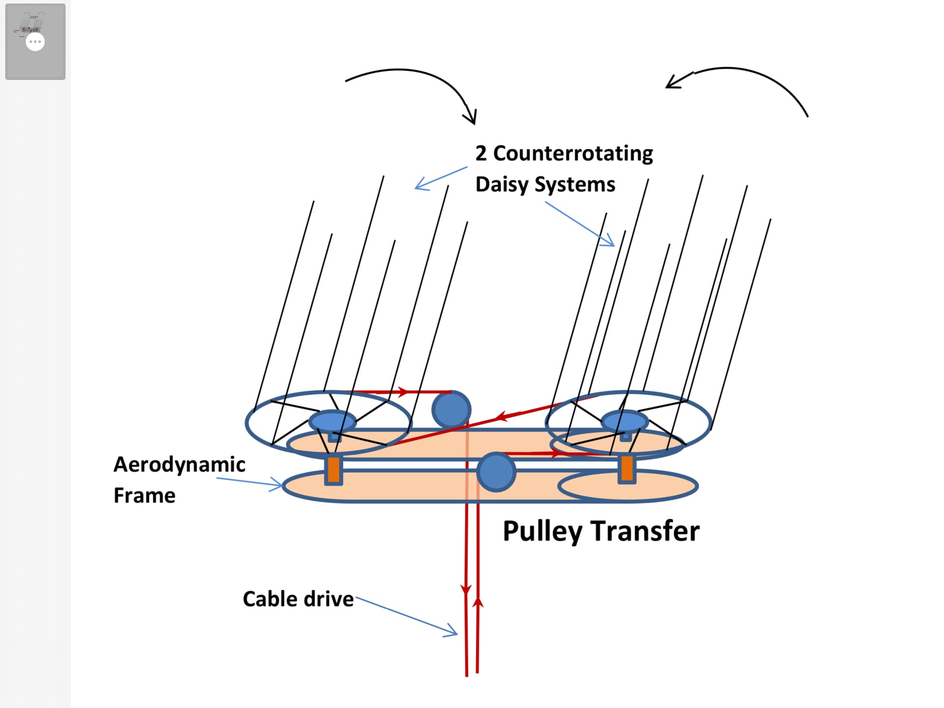
Since my original post with my primitive drawing of a “thingy” to convert Daisy to cable drive, I realized that the frame supporting the drive wheels can be aerodynamically designed to supply lift to the device to compensate for the extra weight. The frame would be similar to the frames on the “Skypull” drone or the “Skywindpower” design. Here’s my best rendering of a possible design. It is important to have two counterrotating systems to neutralize torque and prevent the cable drive system from twisting. The large diameter of the TRPT system is advantageous since the drive wheel of the cable drive can be much larger than the driven so that the cable speed is faster (thinner and lighter cable) and the gear reduction on the ground can be simplified.
We try such design with kiwee. I mean a design where the cable from the cable drive is also used for the right angle features. It doesn’t work because the right angle part “see” the whole traction from the kite resulting in huge losses. The right angle part must be made of a inner belt, like on kiwee now, otherwise with increasing traction, you will experience huge loss, friction, heat, wear and so on
Do you think it is possible to combine TRPT in the upper part and rope drive transmission in the lower part (an example (?) on the second sketch)? The reason would be to associate the length of the rope drive with the stacking potential of the TRPT rotors.
Right angle transmission needs 3 static points to work. On kiwee, one is the drive rope, the second is the kite line and the third one is the fin. Remove one of those and everything goes wrong in a second. Theoritically yes I think it is possible but you will need a huge fin to counteract the huge differential tension between slack and taut strand of the right angle belt. In real world, knowing that managing only a rope drive of small size like kiwee is such a mess, I think you will get into huge trouble to deal with that. Nevertheless, it seems possible
A drawing can always look convincing since it “does” what the artist wants it to do.
But
Does the drawing reflect reality? Are all the forces taken into account?
From time to time I make some drawings, but not for that reason, only to try to see if some problems can be solved. Usually this happens when other, more serious problems arise.
For both questions, the answer is likely no. But the forum may be useful to eliminate some ways, avoiding a blind alley.
I fail to see why a serpentine cable drive as described above will result in high tensions. Let’s assume that two counterrotating Daisies produce 2 kw of power when rotating at 60 rpm. If each wheel of the Daisy is 1.0 meter in diameter then the rope velocity is 3.14 met/sec. The differential force required to generate 2 kw is 65 Kg. If we want to maintain at least 50 Kg force on the low tension side, (supplied by turbine thrust and kite tension) then the forces in the cable drive will be 115 Kg and 50 Kg which are quite reasonable. Lower cable forces are aided by larger diameter cable drive wheels and faster turbine rotation.