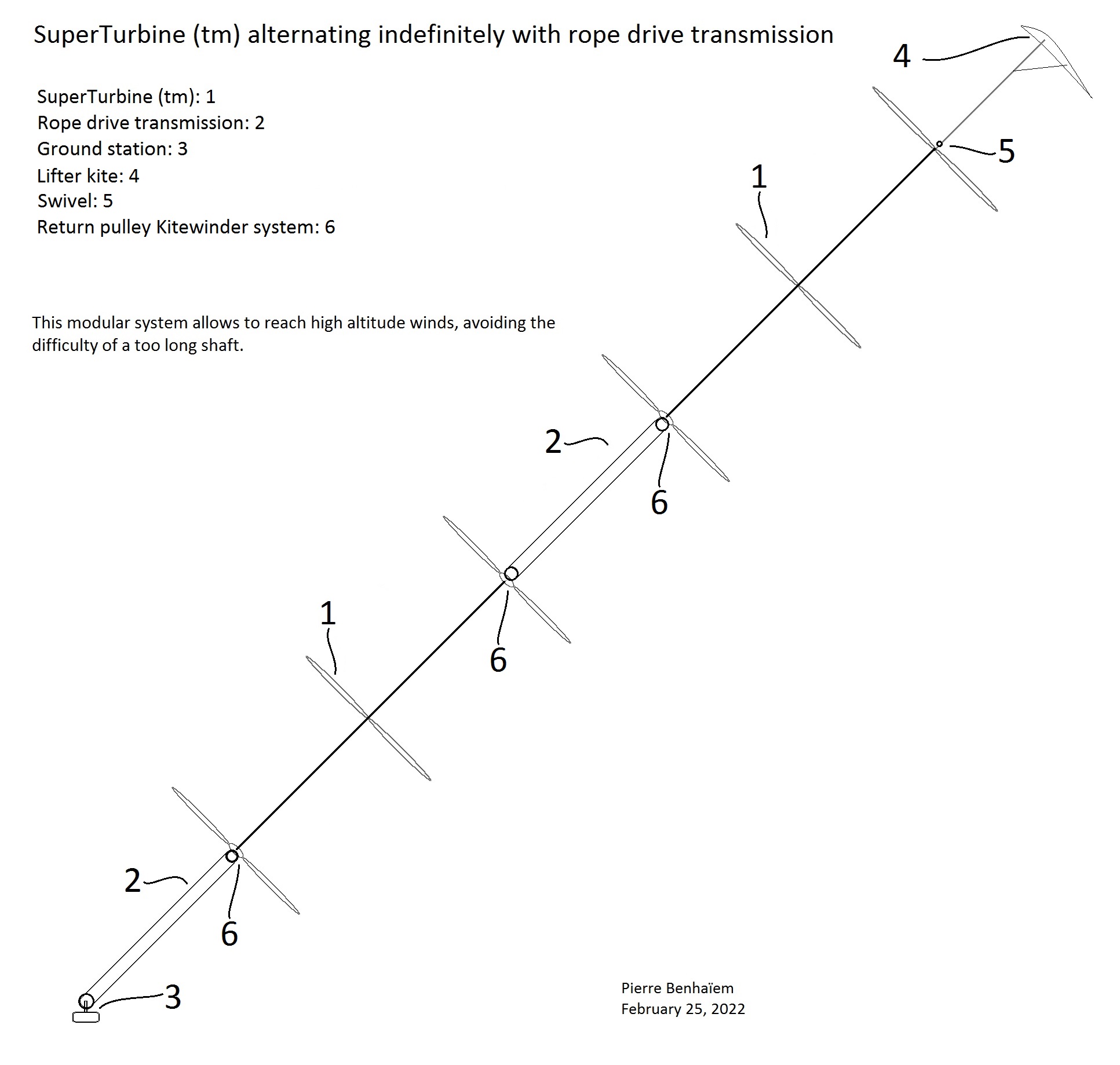
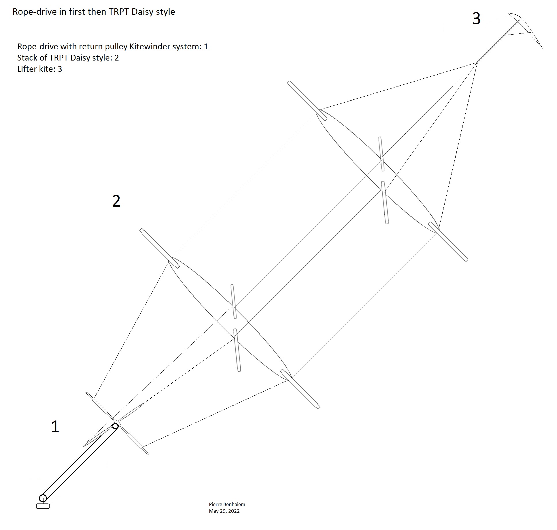
I have sketched a preliminary outline, with placement of the @dougselsam SuperTurbine ™ torque transfer element at the top, and the @Kitewinder Kiwee rope-drive element at the bottom. But it appears that indefinitely alternating torque transfer and rope-drive elements allow to avoid a too long torque transfer shaft. As a result higher altitude winds could be harnessed even with a generator at ground. A sketch below:
A variant with a farm of unities is also presented below. Two kytoons frame the SuperTurbines ™-Kiwees. The lower kytoon allows to reach high altitude with a high elevation angle.
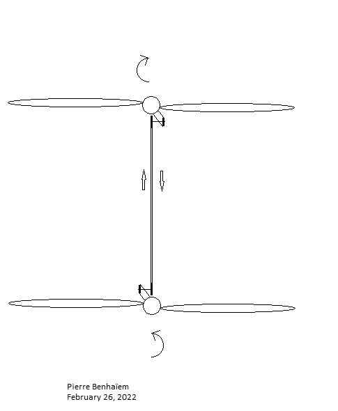
In order to eliminate undesirable torque effects on the fixed parts of the rope-drive systems, two SuperTurbines ™ separated by a rope-drive system will rotate in opposite directions. To ensure the continuity of the transmission system, it is then sufficient to reverse the assembly of the hub causing the return pulley, the rope-drive having to turn in the same direction.
Unfortunately I have not yet the elements to build it.
https://kitewinder.fr/ has some materials comprising propellers and rope-drive elements. All that is missing is a SuperTurbine ™ shaft driving the propellers.
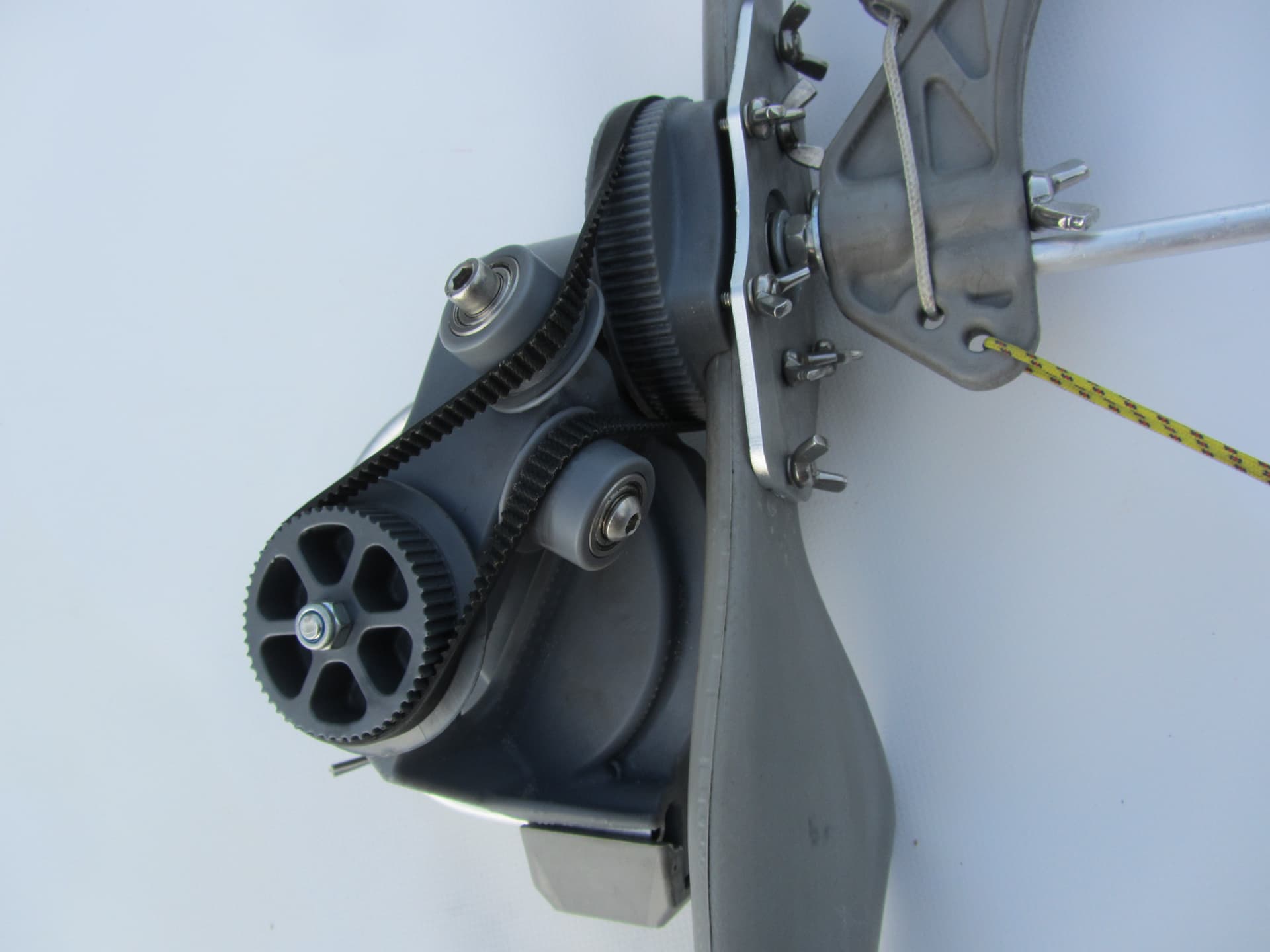
This picture allows to understand better my previous comment. When the belt hub (seen from the front in the picture, between the propeller hub and the return pulley) causing the return pulley is mounted in the other side, the belt turns in the same direction while the connected propellers rotate in the opposite direction.
As mentioned on my two previous comments, rotate a SuperTurbine ™ at the end of a rope-drive system in the opposite direction as the SuperTurbine ™ at the other end, in order to eliminate undesirable torque effects on the fixed parts of the rope-drive systems. As a result twist in the rope-drive sections can be avoided, the traction of the whole transmission system partially also preventing twist.
I’m sorry @PierreB I’m unable to keep up with you here
How can twisting opposite ways at the ends of the belt drive help to avoid twist in the belt?
Do you have any other media which might help to explain the principle of the operation?
In the original Kiwee system, there is no rotating part above the propeller.
But in the system I propose there are rotating (SuperTurbines ™) parts above and below each rope-drive system. So if a significant and undesirable torque acts on the fixed part of the rope-drive system, it can be better to counter this by SuperTurbine ™ rotation in a direction at an end, then rotation in the opposite direction at the other end, in order to cancel said undesirable torque.
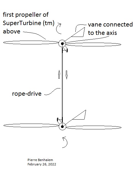
That said as you point @Rodread the rope-drive system is free to rotate around the fixed axis of the propeller, and it is not good. Unlike the fixed part above the Kiwee propeller, here the fixed part is isolated. As a result said fixed part can to not prevent rope-drive twist in spite of the traction. Some tests would allow to see better.
Perhaps a solution would be to connect a vane to the fixed axis in order to fix the rope-drive by wind force, in addition to reverse rotations of SuperTurbines ™:
I cannot visualize how you plan to transfer power from a torsion shaft to a cable drive system. The torsion shaft is in line with the tether and the cable drive pulley shaft is at right angle to the tether. You need some sort of pulley or bevel gear to join these two systems.
As for Kiwee where the tether is in line with the rope-drive. See the device comprising several pulleys of which a right-angle return pulley to drive the rope-drive.
In the system I proposed the propellers are tilted to be perpendicular to the axis and the rope-drive.
The problem is not the alignment by itself but the lack of thing preventing possible rope-drive twist, as pointed by @Rodread.
The rope-drive system (1) at the base could increase the base altitude of the rotors and eliminate the rigid transmission elements. The propeller blades should be robust enough to withstand stress, and have a low TSR to fit the Daisy rpm.
The stacked Daisy style part (2) is supposed to allow torque transfer without height limits simply by adding Daisy units.
Perhaps some other high wind survival means could be envisaged.
Where your design transitions from TRPT to rope drive transmission…
You’re going to want a mechanism to stop the rope drive wheel from turning over from holding torque…
So something like the front forks of a bike with a rope to ground from the crown.
Yes, but perhaps the strong axial force and the ground anchor could prevent undesirable torque effect; but perhaps no. After all the right angle rope drive wheel already prevents for turning in the Kiwee system, in spite of the torque provided by the propeller.
In Kiwee the torque countering stability is provided by a fin.
With your drawing and the suggested “bike front forks” the crown rope is most effective parallel to the plane of Daisy rotation, but somewhere below the axle would do. Having the line going to the ground station wheel… It would not work
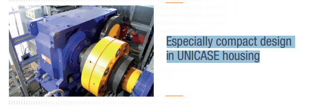
Cableways use rope-drive systems. An example of ropeway technology is provided below.
An extract:
One of the strengths of NORD DRIVESYSTEMS is the especially compact design of the UNICASE
housing allowing maximum torques of 250,000 Nm possible up to size 15 in relation to the size.
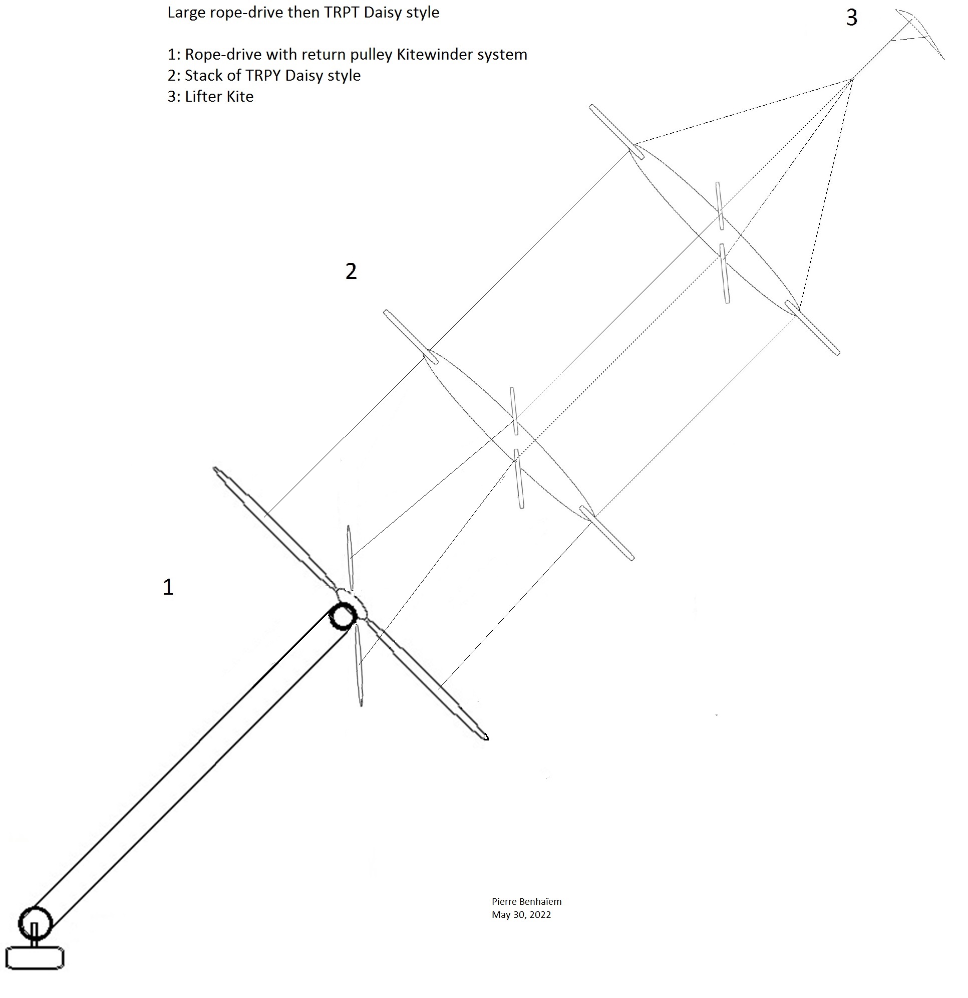
250,000 Nm should be sufficient for any TRPT. Rope-drive transmission, including its variants, has no practical limits in terms of length and transmitted power and torque. On the other hand, TRPT could facilitate rotor stacking. Adjustment of the rope-drive with the TRPT could perhaps be better if the pulley and all the rope-drive system are relatively larger to improve torque transmission:
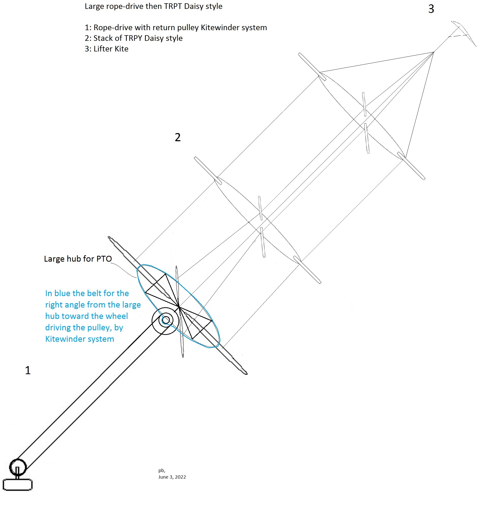
Edit: I add a sketch where the hub is far larger for a better PTO (TRPT torque transmission towards the rope drive via the belt (in blue) for the right angle (Kiwee system, sorry for my poor sketch) between the large hub and the perpendicular smaller pulley via a driving wheel. That said I don’t think that could work well. The idea is (was) to combine the advantage of the length of rope drive transmission, with the possibility of stacking the TRPT rotors.
While I do spend a lot of my time (too much) riding such cable drivetrains up the ski hills, I would have to just point out, brainstorming is fun and a good thing, but always remember, everything works great on paper or as a drawing of any kind. It’s when mother nature gets ahold of it that you start to see where you are really at.
So far I have not seen anything conclusive even on paper in the AWE field, including in my own sketches. But who knows, maybe a better overall design will get it all unstuck.