Windswept and Interesting Ltd

Let’s try to push the unitary comparison with approximate numbers, for a wind of 10 m/s.

Consider a wind turbine with an 80 m diameter rotor sweeping 5000 m², power coefficient 0.45, power 1.35 MW.

To obtain 1.35 MW, Daisy, for a power coefficient of 0.15, will sweep 15000 m², i.e. 5000 m² per rotor, but in reality 23100 m², i.e. 7700 m² per rotor, because of the coefficient of 0.65 taking into account the cubic loss of cosine with an elevation angle of 30 degrees. The diameter per rotor being very slightly less than 100 m, we would have per rotor 3 (perhaps 6?) blades 20 m long and 4 m wide, each weighing approximately 1.5 ton (I base myself on the mass of 0.2 kg of an original blade of one meter, by applying the law of increasing cubic mass), so, for 9 blades (3 per rotor), approximately 14 tons, and 28 tons if 6 similar blades per rotor are required. Add to that the mass of torque transfer and rotor rings aloft. All this will be much heavier than a 80 m diameter wind turbine rotor without the nacelle, and will require a gigantic lifting kite, proportionally even larger due to the exponentially increasing mass.

In the drawing, the roads are deleted for the AWES. But highways would likely be required due to significant maintenance, including the replacement of elements due to flight stresses.

Also adding the difficulty or impossibility of secondary uses of large land areas due to the changes in wind direction, due to the vagaries of flight, especially at low elevation angles.

The “boring, solid and heavy wind turbine” can sleep quietly, not likely having to move to make room for such AWES.

It’s just the generic 3D Daisy Kite Turbine design I published before.
3 rotor levels 5 blades on each.
There’s similar area being swept by the legacy turbines and the Daisies.
At the scale depicted here (~5MW at most) I reckon a Kite turbine would be configured with more blades and levels… but it’s a guide. Also the mid Daisy rotor is too close to the lowest one.

That’s a harshly pessimistic analysis at every step @PierreB
But yes, thanks every one of those points needs answered

@Rodread , and in my opinion Daisy is one of the most promising AWES.

I don’t see any AWES competing with conventional wind turbines, but markets for individual use (like @Kitewinder Kiwee) could emerge, such as charging your car as you did, or your home.

Besides that perhaps AWES could harness high altitude winds that HAWT could not reach.

I would rather say the visual impact of the AWE setup seems much less than the windmills.


A large single looks - kinda big

more detailed technical chat from @Rod

1 Like
2 Likes

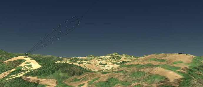
A kite turbine farming landscape may look roughly like

A cleaner 900 frame render
took long enough on my poor wee laptop
Youtube does not render it at high quality even if you choose 1080p

Maybe I should upload the original here
Vimeo does quality better…

How to keep 18 x 100kW kite turbines spinning neatly spaced over a field.

A network of networks
Got my grasshopper model working lots of moving parts simultaneously and still able to look around in real time.
Now you can all see networks of kite turbine networks in your sleep too

2 Likes

Windswept and Interesting needs you!

We need your brutal honesty to see if we have missed any risks / not properly identified any weakness…

Or maybe just not communicated our mission well enough.

Please feedback on your understanding of how you see kite turbines and our company prospects.

On kite turbines

A founding AWES mech Eng recently commented - In comparing kite turbines to the Swan bridge situation, where a single tower, multi-line suspension bridge had to be retrofitted / reinforced with extra crossing lines to stop sway… is a problem because kite turbines also have multiple lines.

Why I think this isn’t a problem
For 1 there are no humans on the turbine.
2 The bridge lines had to be networked to fix the problem.

Yes kite turbines have dynamic parts. The parts can move, but only in limited relation to each other axially, radially and in circumferentially.
Torsion happens, to a limited and known extent in kite turbines, because we use a cylindrical horn network of longitudinal and circumferential lines around rigidised rings to transmit torque.

Kite rotor dynamics ensure a stable flight which pulls the network open radially, upwards axially and around.
Kite turbine line tension ensures there is enough torsional rigidity for energy transfer.
The initial horn shape prior to torsion acts to expand TRPT rings. The result of TRPT is a spiral line set made of straight lines segments.

(I like to think of the resultant spiral like a straight line path through curved spacetime… Hmmm… Thought process above my pay grade there)
This is a company issue - We need more experienced engineers to help define, build and test Kite Turbines.
We are in phase 1 of a project with a set of plans
But

It’s been a year since Network Kites and Daisy network kite rotors - #117 by Rodread
And We’re still trying to arrange enough funding to test a 10kW automated system.

What do you see as the biggest obstacles to getting funding to test kite turbines?

Where are the risks for W&I?
I want to present our risks on a new site we’re developing kites.energy

The Mech Eng from earlier also considered the multiple lines as more of a tangle risk - and the system as potentially less able to scale… all of which is addressed by tensile networking. Nets are easy to untwist / don’t tangle and enable scaling by exploiting the limits of AWES blade architecture in layers (axially, concentrically and by radial number)

Please pose some challenges we need to address

Thanks for brutal honesty
Rod

  1. Eliminated the tangle risk.
    If it a concern I’d seek rectifying that. How I’d rectify it is, carbon fibre tent rods. There fairly cheap and easy to get hold of. It can still have the cables running through the rods and nuckle joints at each intersection. Yes it adds complexity but it improves reliability. Which is much needed for consumers.

  2. Scale, with the carbon fibre additions you have the potential to go far larger than you previously thought. because of the extra rigidity you can make cage section. Which you can stack or expand. For example
    image
    Most engineers I’d imagine would be familiar with this concept. This Is just one example of a polyhedral net. It also give you the ability to control line tension. Most cnc machines have armoured cabled. To protect the cable form damage. This would be no different. Sure it will add to the weight, but it give you more options. Even the potential for a solid state version with blades incorporated.

  3. Setting, where and on what? I see most turbine towers get decommissioned when they are past their allotment time. However some maybe useful long after the standard turbine are done. The inferstructure already somewhat there. which reduce time and installation cost. Reduce time to market is also a bonus. In your case it would be somewhat like the windsock at the airport tied to a pole. And could fly parallel to the wind. Regardless of location, be that a top a tower block, pylons, ground based or out at sea. Each design will have to be adapted for location. You already know some what about regional various in the rules. Each location and local authority may differ somewhat. So best checkin before hand.

  4. W&I risk. would hover somewhere around the right to repair and accidental damage. tend to be a big one for any consumer. As it would Influence product viability on the market and any potential longevity.

  5. Altogether there is potential for a sophisticated and elegant design.
    The blades can have control surface that help minimise sway, control by rc servos.

  6. As you mentioned spiral and space time, it would be prehaps apt to mention archamedes spirals. Running the length of any rig. Id imagine if you could create a stabilising vortex in the centre of your design. Its less like to want to wander and sway uncontrollably. Similar principles are discussed in aircraft design. I just wonder if it would crossover here. As previously mentioned you have lots of options.

Hi @Freeflying,
Struggled to understand your post but I think these responses make sense
1 we use carbon epoxy for rigidity in the TRPT and on the rotor rings.
2 yes we could truss (or shell and fair) these sections for scale
3 for now we’re focussed on dev toward a 50kW product for hilltop farms.
4 we’ll supply modular spares. and dev some more condition monitoring
5 avoiding mass of servos etc in wings for now in favour of aeroelastic flex performance and other handling tricks
6 sounds mildly insane
Thanks

1 Like

From my experience there can be years worth of development between having something that works some of the time to a system that works all of the time.

Have you solved operations in all winds with smaller prototypes?

The turbine is stall regulated - how well has this been tested and up to which wind speeds?

Br
Andreas

1 Like

Perfect question @aokholm
When everything has been well prepared and launched well its fine. But I’ve made some careless mistakes which could be programmatically avoided.

The limit to operation so far has been my personal strength and ability to handle lines…
That’s not good enough to test and define the full turbine capability.
Pulling sideways to yaw stall has been easy enough.
Relying on a personal weakness is not the way forward for operation… Time to bring in the robots.

Thanks Andreas

#1 which part are we commenting; the post in the forum or the webpage kites.energy?

Anyways; I have a few things maybe I already mentioned but may well be repeated.

I would be more worried about the mass of expanding rings and their dynamic behaviour as a gust response. Ideally maybe do some calculations on their inherent frequencies and damping of these. As you will start «medium size» this round, I dont think this would bite you too hard but maybe a potential investor may worry about scaling issues. Maybe its just impossible to fit this in your project and you just have to live with some uncertainty.

The other thing that keeps coming back is regarding the graphics and animations make of multiple wind turbines over a vast area with a shared canopy network. This looks really sweet when running but I cant really imagine how practical handling in zero wind would be for these systems. I think if you go there you should be clear on how this could be feasibly implemented. I dont think the Daisy had such a leap of imagination required as these large systems have. Also I gather a 50 kW may look more like a larger Daisy than these designs. Tread carefully.

I have the impression that many people have a hard time believing TRPT actually works. Im not sure what to do about that, in fact I think to date the TRPT test rig is one of the betters ways to illustrate. But the end proof may just have to be showing working windmills size by size.

I was a little disappointed that 2022 was devoted to only planning and design. I think time is very short, maybe if you could start at least working on some subsystems immediately that would increase the chance of success. Maybe not, and maybe its a resouce issue, but still…

The flexible kite/wing/plite is interesting though a bit vague as a reader. I am immediately thinking this may be a massive development effort. Though with little info its hard to tell.

I just read a book about the history of windmills. The evolution was very slow. Like one design went from DC to AC. Another was slightly better robustness. Even another a teething connection to the hub. Small almost invisible steps.

I have a feeling that you want to take a huge step involving many advances. This in itself is a big risk. The Daisy was a huge achievement IMO. You want to build the same thing but with a few improved features. Maybe just the wing. Or just the size scaleup. Or just running for 1000 hours automated. Or three in a canopied network. Or auto launch/land. Or whatever you think can give most bang for the buck to bring the dream of the huge network a little more believeable.

I think we should also realize there are many ways to generate value. One is to sell windmills and become a profitable business. Another would be to increase share price by developing technologies. Why Im saying this is that this will very much impact what your prototypes should look like. Are they stepping stones to show you are on the right path to something bigger, or are they products that must be sold to a customer an deliver decent LCOE? Or is it just a crap shot at dealing with climate change?

Some thoughts. Id share more thoughts on anything specific if you point me in the general direction you would like to hear about

1 Like

Perhaps building a completely stacked Daisy as on the drawing above as a step (the first design with few (or no?) torque transfer rings in the low part), but not still the network of networks which is a perspective for later.

Using the available soft or/and rigid blades and rotors to save money (mixing soft rotors in the bottom and rigid larger rotors (with higher TSR) in the top then adjust their rpm, avoiding also to have rigid rotors too close to the ground?) then complete by adding rotors to reach a ratio height/diameter that a single or two rotor(s) cannot reach.

If possible remove the backline because it leads to a second anchor which is difficult to manage when the wind changes. In the place using winches as described below for landing.

For takeoff (and landing) and towards automation, some suggestion like putting the rotors one over the other, ready to take off one after the other, the first rotor towing the lines from winches settled in the ground station, said lines including spaced nodes blocking the respective following rotors during takeoff.

It is only suggestions, knowing it is more easy to advise rather than to manufacture.

To the market aspect, envisaging loading car batteries as you already done.

2 Likes

Thanks for the detail on risks you perceive @tallakt brilliant

I’ll go through my take on your points…
Scaling the TRPT rings - Diameter will scale, length of TRPT shaft doesn’t need to. As diameter scales we will be able to move away from the inefficient but simple rod sections to tube sections , trussed ring sections for deeper effective wall width (2nd moment of inertia) and stable wider outer , then onto faired monocoque sections like an aerobie ring.

About network of network ideas… I am really into them. Why… We trust our kids to the safety of trampoline nets, we throw big nets safely out of the back of trawlers in the roughest waters, they expand and work. Net’s don’t tangle like single lines. Net’s are massively underrated in AWES in my opinion.

I roughly estimate that a standard Daisy Kite Turbine will work to at least 200kW without needing anything too smart.
Beyond that kinda scale you’re definitely wanting to farm in a controlled and land space efficient manner. And if all you can buy is unit scales you will want to array them in a neat efficient pattern (notice there are only 18 around near but not out at the perimiter of the topnet hexnet… So each turbine in that net, has space away from the stablising overhead outer net. Net of net designs are still sketches and the parameters can all still be tweaked.

To improve on a standard Daisy > 200kW we may need to get crafty with launch and land to the ground station using centre line tension and a backline able to be upwind of the turbine head… which an overall net just has by default. The big leap is - launching large rotors will not require large diameters. They will expand dynamically once rotation is established. Large diameters destroy the rigidity which you can achieve with lightweight rings. For the next few scales we have enough rigidity for simple ground handling routines. The biggest risk of tangle is blades folding into the net, So for now we will keep the lines stretched out with a backline handling bot. In a tight net the bridles (and potential small top bridles) hold the rigid rotor blades fixed in relation to the net and rigid rings.

Yeah TRPT is a head fuck for sure. Some things just are weird. A skirt with hoops already in it stay out at a wide diameter. A Scotsman has to spin to make his kilt fly out and embarrass his aunties. Oddly, A hula skirt doesn’t have hula hoops in it… but it does have loads of tether lines, go figure.

2022 - Of course there’s been more than just planning and designing. (both massive and essential jobs) You saw a very rough launch mast prototype last week. There are folks developing much larger controlled lifter style kites than I have yet needed to. Yes I’m gutted to only be 1 human too.

Slow evolution in tech happens when there’s less urgency. Necessity is the mother of invention. War accelerates tech. For the last decade I’ve been at war with fossil fuel dependence.
Yeah the network of networks is a long way down the road. It’s not the only goal to score though. A 50kW autonomous Daisy will be very valuable product and should be able to maintain a company or 5.
With that resource, work on larger schemes will be more obtainable.

Thanks - yes Daisy has been a huge leap. Look closely though you’ll see so much you would want to improve on. A few improved features will enable all of those goals you state, 1000 hours auto - yeah, scaleup - yes, three under a net - yup, Auto launch land - why not? All doable.

In terms of products and prototypes. There isn’t 1 suspension bridge or yacht. There are many and they come in many sizes and are finished to many different standards. Not to say build it and they will come… You are right we should aim for bang for buck,… Something like a classy cheap reliable 50kW automated kite turbine should be about the right size spin out product from the work we are doing developing scale.

Thanks again @tallakt
1 Like

Thanks @PierreB
A daisy without pure TRPT (Tensile Rotary Power Transmission) levels will need a large ground station with the Power Take Off raised above the ground for rotor blade tip clearance - not very appealing to me right now. As a tidal power solution - yeah maybe.

Have considered mixing soft and rigid blades as you suggest.
Potentially there is a use for soft kites where there is a definite risk of blade strike crashes… Such as in the model we have to build for Ollie when he does his Greenland trip. But that’s very small scale and low power. Rigid blades are way more efficient … and the top rotor is always ahead of , and driving the lower rotors already.

If your goal is to get rotors to high altitude using a long TRPT… Making sure you are running the TRPT within it’s capability is key. You need sufficient lift to maintain the TRPT. Lift can be added to a TRPT by adding blades to it… Fairing the rings and lines can also act to give lift and expansion. Soft kites as blades are likely to be more draggy. Having said that - maybe - like that Big Spinning Bol kite we featured on the forum a few weeks ago, stacking those without any other kite is an instant scaled turbine solution. Please try it.

For now I’ll keep the backline for the advantages.
Assuming the backline bot relocation breaks down and it is stuck in 1 location and the wind changes… Depending on the backline link height onto the lift line - This limits the travel of the turbine downwind, It’s going to act to yaw and eventually stall the rotor. Assuming the winch of the backbot and the lifter controller are still working, we can land the turbine & lifter then fix the Backbot.

Yes
Successive launching of the rotors from a fairly large pre spin cage which attaches successive rotor to TRPT lines ( or just sequentially stepped releases rotors pre connected to the TRPT lines) is a very appealing idea for scaled launching and recovery to the PTO

The suggestions are all welcome.
Loving your enthusiasm for idea generation and creativity. Please keep it up.
And yes - storage has to go hand in hand with intermittent renewables generation going forward and at scale too.

1 Like

image