It looks like that man is happy
Anyway just a quick wee retake of screen capture showing separation of turbine blades from lift net

It looks like that man is happy
Anyway just a quick wee retake of screen capture showing separation of turbine blades from lift net
Looks like his arm must be getting tired! ![]()
Perhaps you have explained it elsewhere, but what’s the process to power control & survive high winds?
Generally what operation regimes do you have experience with? Approximate windspeeds, and approximate desired operation range for the 50kW version.
Stall control is interesting, because maybe the shaft can’t support the torque requirements of keeping the speed down in high winds. Maybe or dare I say even probably?
One means I could mention is to couple angle-of-attack of the wings to shaft twist, typically using front and back lines connected to different «phase» of the shaft… not sure if that was understandarble…
Another of course would be local pitch control at the kite though that is dependent on active control at the kites and single tether attachment point, making a few other things hard.
Yaw stall I believe is only used for smaller windmills historically. But we also have elevation power control., same thing I guess
Thanks @aokholm
Without automation, our high wind survival tests relied on my personal willingness and limited strength to battle the backline and release or bring the rotor back to ground. If I was nervous I’d Yaw stall to the side while pulling the lifter down. We’ve tested through gusts over 18m/s and seen the tips of “rigid” foam blades flex out.
I like the idea of blades flexing off / flagging out to smooth gusts. But the effect is only so useful as it’ll stress the blade root, and at the top may increase power.
I tried some elastic bridles. meh maybe
Flexing inward (more banking) with a gust would be better. probably requires more inboard blade length. Which is going to be heavier but it seems a lot safer if the rotor shape morphs further into an expanding sock.
Wing C folding deformation may be interesting - Don’t think I’ve demonstrated nor purposefully tried it.
One basic effect to adapt to wind is just as @tallakt also described. The bridles are fixed to the TRPT lines. As the TRPT lines are loaded in torsion (Twisted) This pulls extra pitch into the outermost ends of the blades. This effect happens less at the fuselage / ring-root where pitch is fixed to the ring.
Back when I was testing a version with a high solidity double disk of rip-stop and soft kites… We tried setting the bridles to two different TRPT lines as @tallakt suggested. The idea here is, you can either pitch or twist the blade relative to the amount of twist induced in the TRPT lines.
e.g. if the outermost bridles are tied ahead (or out on TRPT) and the innermost bridles go straight down their own TRPT line (or onto a centre axis line) then more twist in the TRPT results in more blade twist.
Among the other options (without putting cyclic pitch controllers, bridle drivers, aero brakes, furling devices, flaps… any heavy devices in the blades)
A high elevation Yaw stall / slowdown. By releasing the backline so the rotor goes higher you can depower the rotor but it has less directional stability from the backline now.
We’re going to have a lift kite controller to assist in various yaw functions.
Rotor dynamic expansion and contraction control won’t be part of the 50kW sets I shouldn’t think
A centre line may well feature again on the 50kW sets
With a centre line you need to keep it’s length adjusted to compensate for the amount of twist compression in the turbine and pure TRPT. The centre line can be used to affect bridling as above, even more so if you can control it’s length.
A soft link could also be used to trigger driver collapse.
A pivoting, hinged or buckling fuselage / blade linkage may be viable
maybe upper level bridles and inter rotor layer control
With networks - you get options
A pulley here - A linking line there
Even I managed to make a flying wind turbine using nets.
When it all gets above (don’t know m/s for the 50kW yet) the backline bot will yaw stall the stack of rotors to a side stretch, then recover the lifter, then from a slight upwind collapse the rotor stack to the ground.
Sabotage by knife or drone is another option for bringing a kite turbine to stall or bringing one down all together… But we can avoid that
Tough to know. Will depend on how rigid the rings can be. There will always be slowing available but stalling with only torque may not always be available (not even in the list above)
Forgot,
there might be a way to use TRPT to control sweep angle
If inner bridles are on TRPT and the outer go to a central line (or influenced from above layer) .
Probably needs a hefty bit of bearing though.
Please let me know if you want a copy of the simulation files to analyse this proposed kite turbine configuration

You may find flaws - derive alternatives…
Would a walk through video of how the simulation works be helpful?
I haven’t been paying attention, but I don’t recall any torque transfer system having any, or any credible, potential for an automatic launch and landing mechanism.
Yes Roddy, what I noticed from day-one with all the “we WILL power X hundred homes” claims was that “these people don’t even have a kite with automatic launch, let alone an entire automated AWE system”. Further, the repeated statements of “replacing hardware with software” could have been conducted on small models - No need for a half-MegaWatt machine to develop software. And why build and crash million-dollar prototypes if they can’t even put together a self-launching kite?
The last video I made with what was left of the Sky Serpent after a few crashes,

starts out with a passively “automated” launch, where all I did was toss aside a couple of pieces of 2x4 lumber holding down the kite, and it “automatically” launched. I did it that way to show that it is possible to have a working AWE system that is easy to launch, without requiring any special equipment or a large crew. Just a baby step toward some semblance of real automation, but it certainly was very easy. I could have then left for lunch and come back and the system would have still been running. No computers required. The on-off-brake switch was optional, but good to have. Easier to pull down, or leave to self-descend unattended when the wind died, if it is not spinning fast.
Nice casual launch skills @dougselsam
I wont conjure up sympathy for your lack of effort.
This is like when a politician says, “I’m no scientist, but …” and then proceeds to talk nonsense and push a policy which ruins the progress of a nations innovative capability.
Paying attention is useful. We’ve gone over this together.
I’m replacing the role of - me- the bit in the field which launches a lifter, connects it to the turbine head, and releases them upwards to 35 deg using a backline, then controls how the backline is held until such time as a recovery is needed. At which point, reverse those steps.
It’s just groundwork handling mechatronics. This is the easy bit of AWES.
I mentioned BackBot function replying to you in previous threads. BackBot = a backline handling robot for launching, connecting, raising…
Did you ignore the idea? Kite Turbines have commonly been ignored by other AWES companies so
Since you asked, I’ll follow
Looking at comparisons in alternative AWES company launch systems…
Well we don’t need any of those dodgy high mass catapult launches, drone VTOL launches, rocket, or shaky spun arm launches. (I mean we could use them but IMO they’re shit)
Think of our plan as a mix of Kitepower and Skysails launch
How about we look at companies such as Kitepower. Just stretch out all your line, Manhandle then inflate a massive live kite on the ground and let go of it’s trailing edge for a fully powered launch. wooo - that’s fun. Fully automated - No, Automation viable - yes. Already a product.
Skysails the original auto launch and land - pretty good. We’ll have a mobile arm top launch, a bit similar to their launch arm for our lifter, Except very much smaller for the same power and we only need a proportionately smaller kite controller. And not yet at the ground station That’ll come later.
I admit to not having shared a lot of gritty detail on BackBot yet.
Shared Hundreds of X more info on what goes on here and what works than any alt AWES company effort.
Probably your concern is about how to stretch and lay out the turbine and TRPT on the ground before launch. Do it neatly and it works a treat. Have you tried it before believing something is impossible?
Poor attitude @Windy_Skies Go try flying a kite turbine instead of doubting
There is no real problem in launching a torque transfer system because even when launched it stays close to the ground…
Yes. That would be a part of the (automated) launch and landing. Do you see what you think is a potential and credible (cost effective, quick, etc.) solution to that?
I rarely comment in your threads, I decided to here because you asked…
You’ve built up too many assumptions about me and are too defensive I think.
I think I’m missing automatic storage, mainly. Then automatic laying out, launching and landing, retracting again and storage again.
My assumption is that you’d like to not have the thing laying outside exposed to the sun and the elements to degrade faster and get tangled up. You’d also like to place them closer together, which you can’t do if you have to maintain two tether lengths between ground stations for fear of tangling the tethers. Also you’d like to not have to maintain a perfect lawn to not damage the system, or not have access to your land while the system is laying on the ground.
If your system is sufficiently cheap and not too big I don’t think automation of the above is necessary, then that’s just a drawback that hopefully is offset by it being cheaper.
We do want lifters at high altitude.
I’ve typically flown very short lift lines so far because I didn’t use a winch release on the line.
Higher lifter altitude gives you more time to react on the ground and recover everything to the Backbot if necessary.
Thanks for the questions @Windy_Skies
The intent is not to have to lay the turbine on the deck during calm weather. The mast head height and position holding of the backbot is enough to keep rotor tips off the ground.
We would lay it down for further securing before an extremely wild wind event.
In normal very windy conditions we expect to fly high.
Given individual turbine handling with a backbot… 2 turbines do not need to be so far apart.
I wouldn’t know where to start making assumptions about you windy you are still anonymous and that’s fine by me
Sunshine  yeah it’s easy to forget to factor that in designing in Shetland
To keep things easy…
Here’s a quick rough sim demo of what a BackBot should do

Considered various versions.
So far it’s really not necessary.
It’s a lot of extra drag and mass.
We may eventually move to using recovery to the ground on a retracting centre axis line.
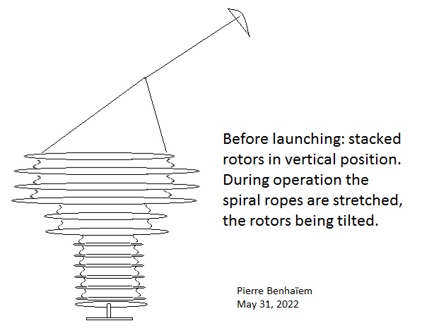
@PierreB , I also simulated and tested another method to concertina drop the rings on top of the base station using either 1 or 2 backbots. This avoids needing bungee in the air.
The basic principle is to use backline to pull the top bearing of the turbine 180 deg around to upwind of the ground-station. Then shorten the backlines as you approach the ground station, to drop the suspended rings in concertina pattern as in your image.