@Rodread , indeed spiral ropes would add some mass and drag. The alternate solution you describe seems to be a possibility.
Another mean (?) would be the rotors equipped with controlled removable jaws and sliding through the tethers in rotation or when the rotation is stopped (I don’t know yet the used mean). The rotors would come up and down as messengers (?). It would be also a (likely more or less feasible) mean to overcome wind overspeed.
Yes, that’s a possibility we discussed previously…
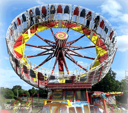
The easiest way to think of it is like a fairground centrifuge wheel ride…
Here’s the ground station
Before we automate… it’s easiest to put yourself inside the machine to work it out.
All of this has to happen while spinning
If each “passenger” (robot) has a winch controlling the length of a main torque tether line.
And in sync they all release ~14m of line it’s now time to attach the next rotor level to the lines.
Your action would be
Pick up the rotor from the top of the stack from the floor
Set the rotor fuselage TRPT line clamp connector to the Line at the 14m mark
repeat until all rotors are deployed, enjoy the ride.
When you get dizzy or the wind dies. reverse the procedure.
Unfortunately I didn’t have a spare centrifuge fairground ride available for my early tests otherwise this is definitely what I would have done.
Now we talking! That looks the buisness!
Might be hard finding a fairground ride going cheep.
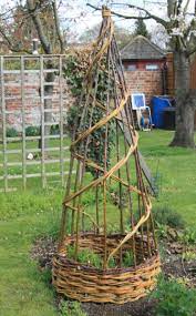
However? not to fret! You could always mod a human hamster wheel to do the exact same thing. Either by cold forming over a jig with strip wood. Cold rolling be that aluminium or steel? Much like these chaps have done.
It also present the possibilities of a direct drive. With the easy of transportation also a bonus. There still room for a variable angle mast which can adapt to wind conditions.
Ive just checked to see what would be the easiest option
You have gymnastics wheel. A yoga wheel. Hula hoops Of various diameters.
There is a verity on Etsy. I’ve no doubt that there might be other vendors. Maybe a fabrication shop that might be able to bend one up. Cheaply. If you only have to get the materials . just a rough estimate for 40mm* 3mm*5000mm aluminium tubes are currently £36.78 plus VAT it is about the same for square tubing. I don’t know if you have a bench to roller? If you do? cost comes down because it only time and materials. If you don’t have a roller? They widely range in price eg. https://www.ebay.co.uk/itm/224819522227
Could be worth having a look about. They seem to range from about £75 and up. Just depends on what on the table? I like what I see so far.
Ah yes, I see what you did there @Freeflying
When I suggested putting ourselves in the machine.
like in an imagine what you’d have to do way.
As much as I love daft circus toys and really want a CYR wheel… I am not volunteering to spend my days in a washing machine drum pulling kite tethers.
Agreed there are more exciting way to spend your days. Sorting a mess in the rigging can become a chore. My thinking was more components, than being a hamster. I hate when cables get tangled and you waste a hour or two just undoing them. No fun there! What I had in mind was using the wheel with internal attachment points leaving the OD to do the work. I hear you can get gear ratio of 100-1 or higher. Plus you can add as many motor or generator parts as need. Some people have turned the whole OD into a magnet ring. With coils spaced as and where need. Sure it fun being on the hamster wheel. Much like the best Roman and medieval construction methods. Another bit of tech to be considered is interwoven net structures
I was trying to find the diamond pattern to suggest another angle of attack.
A helical woven column attached to the outer ring. Often seen in architecture to provide rigidity and flexibility in earthquake zone. The idea Might help prevent a few nasty tangles and provide a firm Anker point. For the TRTP. It just a thought . I hope might inspire a few ideas or investigations.
Might be weird this but I enjoy untangling lines…
I was told last night at a school dance that this string of balloons is too tangled - impossible to untie - Joy, allow me - 2 minutes later. yay.
OK let’s get this nailed in - the operating principle of Networks and Kite Turbines AVOIDS tangles.
The very first TRPT I tested was a kids-toy pop-up-tunnel - helical rigid components are not very stable in my opinion. I’d love to see more scientific analysis of that. Prof Fuji at TMIT who used to do helical antennae deployment for space applications and also does rotary TRPT AWES now, may be the dude for the job.
Straight conical horn with rigid ring grid network geometry gives a different torsional rigidity profile in the TRPT “shaft” - It’s the one I like
I gave it some thunk. I’m unsure where to find the exact paper or vid I’d seen.
I do believe it referred to geometric structures.
It would have been a mini version of
or similar structures. The technique is widely used in architectural design. So I believe your best bet on finding a paper would be either in a maths publication or an architectural publication. It Something I’d seen on YouTube a while back . where I believe the architect was sat behind a model with a small tower in a shaker plate. I remember it flexing. He was demonstrating with reduced materials strength could be the same as, if not better than standard construction. A single helix won’t be strong enough and will be prone to collapse over time. It might be worth taking a look at earthquake structural design. As these structures frequently are found in those areas of expertise. If I recall correctly he guy doing the presentation was from around western pacific region.
@Freeflying
Earthquake survival and TRPT torsional rigidity are very different energy regiemes.
TRPT therefore has very different material optimisation as compared to the lateral stability and shear resistance required for earthquake proofing a tower.
The TRPT threads on this forum have a lot of examples of how torque transmission can be optimised over long distances.
Or just look at a video of our old analysis
Just got our Technology Assessment Report from OPIN Offshore Power Innovation Network
Turns out that Kite Turbines are real and on the way up into your sky
AWE “news” - always set in future-tense. Good thing our lives don’t depend on these predictions actually coming true, because for AWE in general, the track record is pretty dismal.
With the much smaller radius, less efficient and lower aspect ratio airfoils, higher turbulence closer to the ground and behind your other rotors, and lower tip speed ratio, the cone behind your turbines could be wider? You could test that with a smoke generator, or smoke grenades, or I’ve seen some old simulation results with code posted, like here, when I look for “yawed rotor wake.”
We had dense mist / fog with some wind yesterday…might avoid needing to release smoke.
Further significant contributing factors to the wake will be
The annular disk elevation should cause wake steering downwards (like any kite)
There are inner tips in the hollow centre. Yeah that’ll look complex.
The bank angle (outertips down) will reduce spanwise flow outwards which may reduce the vortex severity. - And who knows, may even narrow the wake
I’m not overly concerned with exact wakes yet because the whole system is dynamic, plus there are so many possibilties and parameters to model, and not enough pc cores lying around.
Physical demonstrations have already shown stacking with good efficiency and smooth rotor power, so gathering real world data from systems with more obvious improvements seems more urgent.
A few points towards the positive on this…
Kite turbine radius will not always be small because the rotors are tensile in operation. Small radius loops means a lot less line drag, for now it’s a real bonus. Line drag kills AWES performance.
Which brings us to efficiency, Yep, Kite Turbine blades have been simple and stubby, super cheap to build and easy to opperate even with minimal networking. They don’t have a slow heavy root like a wind turbine and they weigh far less per length, if that’s what you mean. I susspect long skinny (high aspect) blades can be networked into neat turbine rotors with multiple circumfrential band lines and bridles without too much bother.
Closer to the ground? On my tiny tests - fair enough. But these are airborne turbines, They stack and the transmission can extend. They operate closer to the ground than AWES which have to reach high altitudes to operate without crashing. That suits offshore operation fine and uses less space onshore. but will on similar power scales, operate higher on average than most standard wind turbine rotors.
Lower tip speed ratio is correct for now and certainly until we finess the blades and add fairing to the bridles, yet still I suspect it may stay that way with higher blade number rotors.
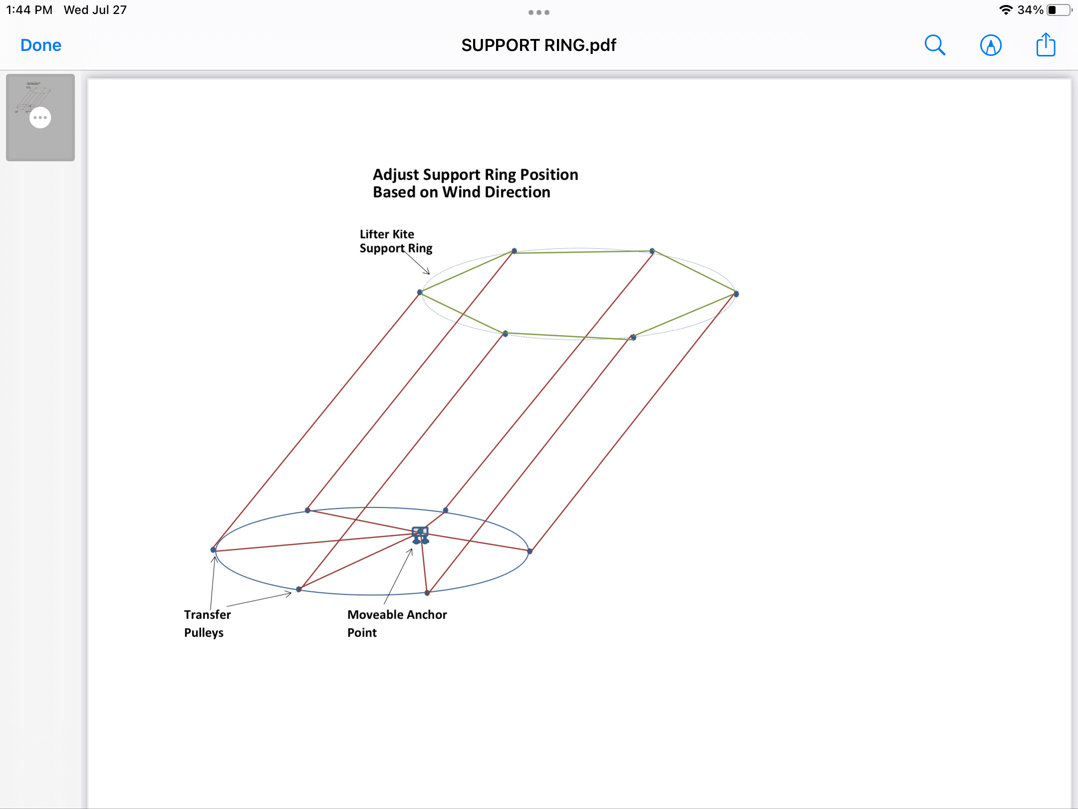
I thought of a way to adjust for changes in wind direction in your wind farm using only one moving device. If all the lines supporting the lifter kite ring pass through fixed transfer pulleys on the ground, and are connected to a moving device then we can simultaneously adjust all the lines. The only problem with this system is where do we plant the Daisies?


 . I hope might inspire a few ideas or investigations.
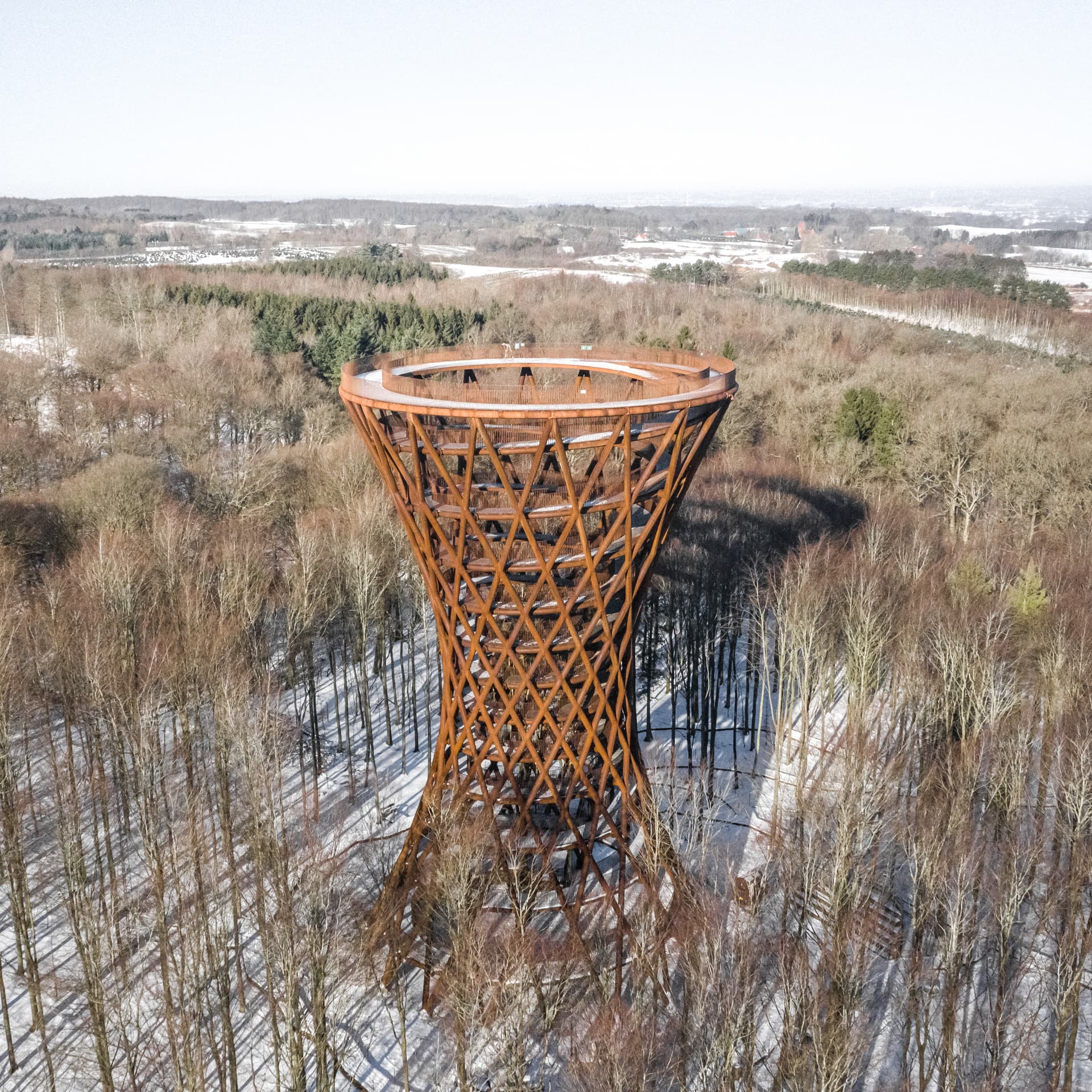


")