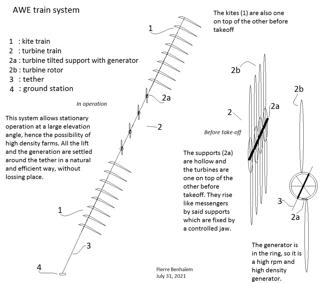
As shown on the sketch, the turbines rotate around a ring which is connected to a support that surrounds the tether and squeezes it with jaws. So the turbines do not rotate directly around the tether which is not their axis as the turbines are not tilted.
Units are in contact only through their respective parts surrounding the tether.
The turbines face the wind direction collectively by the ground station being on a swivel which rotates according to wind direction.
Yes. I think all elements should be stacked toward the tether end before and after operation.
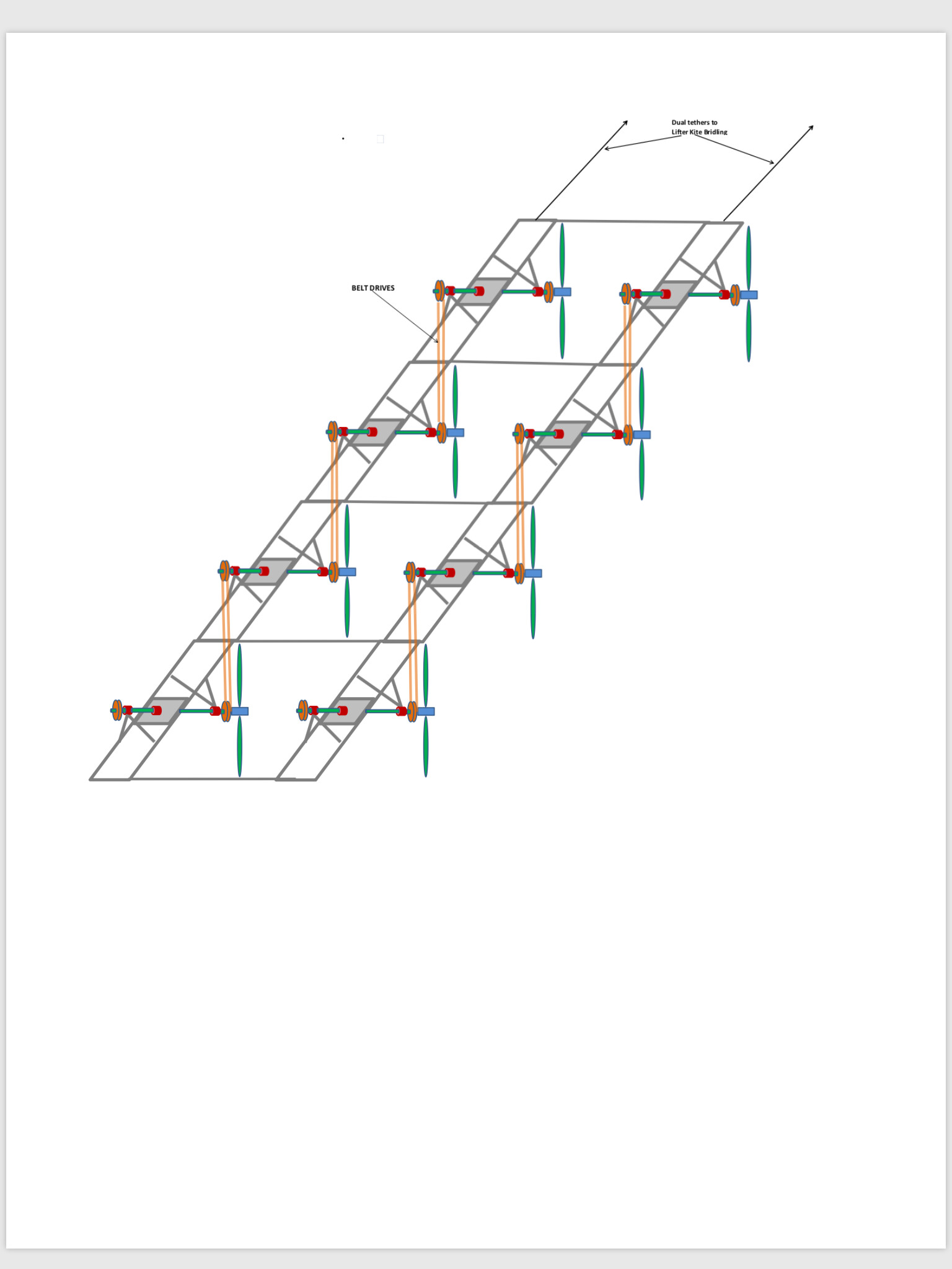
It is not easy to implement several rope-drive systems by using the same tether.
For applications where light weight is of utmost importance, such as in aerospace and motorsports, Calnetix’s high-speed motors and generators are designed to provide maximum power density while maintaining high operating efficiency and good thermal performance consistent with design requirements. An example of a power dense machine that we have designed and manufactured is rated at 100 kW and weighs 7.7 kg in a 2.3-liter volume, which is equivalent to a machine power density of 13 kW/kg and 43 kW/liter.
The real problem I see is the difficulty of control of both turbines and lifting kites, particularly with stacked soft kites. Trains of semi-rigid kites are usual, but rigid kites become too heavy when the system scales up. Moreover the AWE train system uses far more material than a crosswind soft kite for reeling (yo-yo) mode as an example.
A rigid frame is too heavy. The tension of the tether should be used to stabilize the turbines, as shown in the video below.
We can integrate a tube around the tether (still as on the video) then make sure that the plane of the rotor is vertical and therefore not perpendicular to said tube (unlike the video).
If you want a ring like I sketched, you just need to install spokes and connect them to the tube.
I was able to see with FlygenKite that the tension of the lines was sufficient to maintain a rotor via a support bar, even with short tubes (video below). Tension prevents twisting.
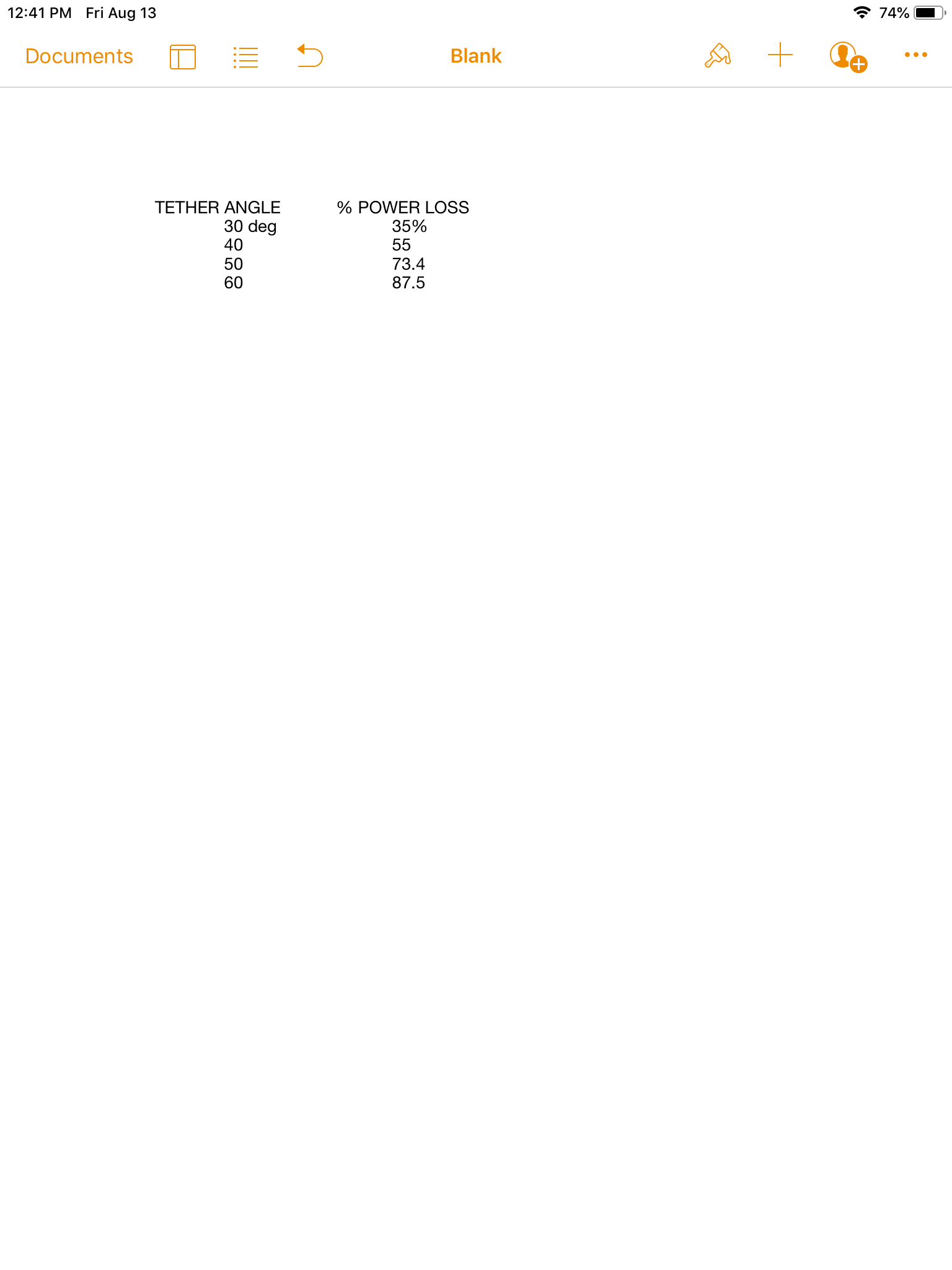
It seems that I am the only person who advocates strongly for turbine orientation. We want to maximize the power of the system especially if we are not operating in crosswind mode. The cosine cubed losses are substantial and catastrophic at high tether angles:
TETHER ANGLE % POWER LOSS
30 deg 35%
40 55
50 73.4
60 87.5
Even if the system weight is somewhat higher due to directional vanes or frames, we compensate for this by increasing the size of the lifter kite. Rag & string is cheap!
On my sketch above the turbines are not tilted. But as a result the amount of lifting kite area is quite huge and the control would be very difficult. With the same area the kites alone would produce more power in reeling mode, and far more by using crosswind flight. So I agree with @Rodread to have a tilted stacked turbine with a smaller lifting kite. The loss by cosine is more than largely compensated by material saving.
In this topic, kite trains and turbine trains have been mentioned.
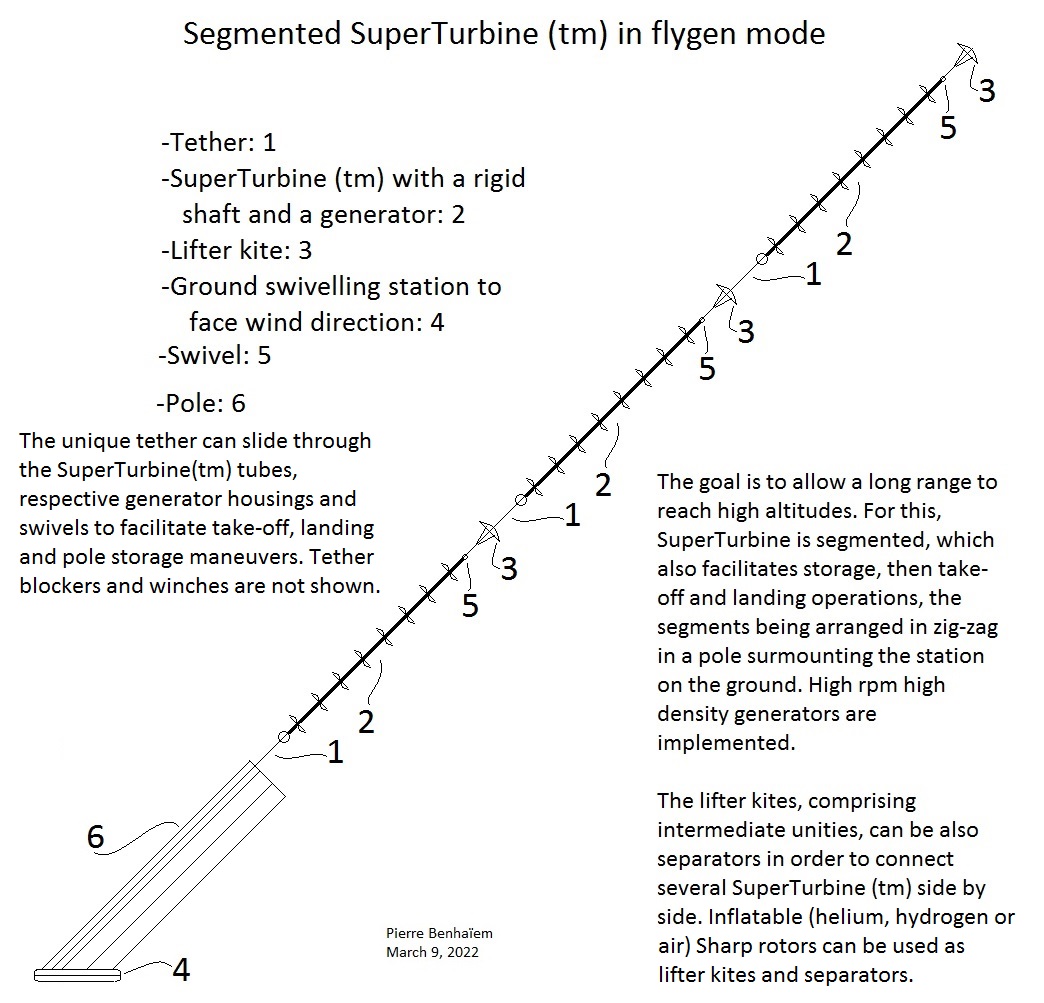
I would like to make the following remark which would need to be confirmed: a tilted turbine train
(@gordon_sp’s configurations are not concerned) like SuperTurbine ™ (sketch of a variant below) requires a lower elevation angle (25-30 degrees) than a kite train, because the angle of attack (AoA) (or the tilted angle if we prefer) of the turbines needs to be high enough in order to not be too penalized by cosine loss, leading to a relatively high spacing between turbines.
A kite train could fly at a higher elevation angle, kite AoA being lower, and lift being mainly wanted. That said spacing between unities can also be significant, as shown on the following video:
In spite of possible spacing requirement (how much spacing with a kite train made up of good lifter kites?), a kite train can be a way for study, leading to super lifters for a reduced used space and a high elevation angle, allowing to support a higher area of not tilted turbines in @Kitewinder or @gordon_sp 's ways.
The problem with the system you propose is that you can’t have a floating generator. The generator will spin with the turbines and not generate power. A way to avoid this problem is to have the turbines rotate in opposite directions on each side of the generator. The generator is still free floating with this system and may be prevented from rotating by having a small air vane attached. An advantage of this system is that the generator operates at double the speed.
The rotating segment (2) including the rotors and the rigid shaft;
The fixed segment including the swivel (3), then a fixed tether carrying the lifter kite then the generator of the following rotating segment.
The generator is more or less fixed if each rotating segment rotates in opposite direction in regard to the previous one, in order to cancel the undesirable torque.
This is like several superimposed SuperTurbine ™, one unity being like on the video below:
You can see that the generator is fixed, then the rotors rotate with the shaft, then the tether carrying the kite is fixed (like the kite). If you pursue, above the fixed kite you can have another fixed generator then a rotating segment, and so on.
The Skyserpent generator is attached to the ground. Any generator between groups of turbines will only be attached to the tether. The tether can easily twist in either direction and this will occur if there are small differences in torque from the turbines. These differences can occur because of different wind velocity due to altitude and different cosine losses due to changes in tether angle.


 Wind Turbine Suspended by Kite - Doug Selsam")