It is an application of post-tensioning. A well-known example is post-tensioned bridges. In this case the tensioning cables would be dyneema, which leaves the material and design of the compressive elements, which are ideally as wide as possible in the direction of the main force. For wings a thick a wing as reasonable, with the tensioning cables mostly along the underside, for shafts as long a chord as reasonable, with the tensioning cables mostly along the trailing edge. Maybe for both bracing between neighboring elements. Maybe you’d use a genetic algorithm for example to minimize drag, weight, and number of wraps, and maximize lift and buckling resistance.
My previous comments about this were mostly just brainstorming. I don’t think I gave an opinion on the viability yet.
We don’t have enough information to make conclusions, but my preliminary opinion is that for torque transfer you only want to use these fairings to resist the torque, and not any gravitational or centrifugal force, as that is for the tether tension. I think that means thin airfoils with a longish chord, and the thickest section very close to the leading edge to have enough cross-section there to resist compression. You can then analyze or test that, does it increase the torque transfer capability enough that it more than makes up for the drawbacks? Testing it, like I say in the other topic, can start out simple: make a few sections and test to failure. The folding/unfolding idea I don’t think makes sense as you’re adding weight and complexity that is not useful in production. I think this idea is probably less viable than adding compressive rings, possibly constructed in the same way.
For wings, if you think it makes sense to make very long wings, which I don’t necessarily, it could make most sense. For shorter wings it could make sense too.
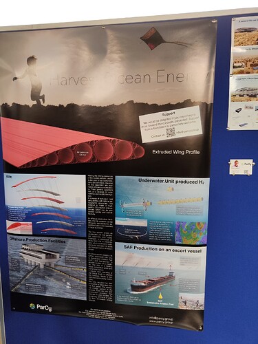
One design could be for example a bridle line every few meters, like the poster I linked to before, mimicking an upside down suspension bridge, and then this construction method mimicking a post-tensioned bridge.
One of or the lightest beam possible is a tensairity beam:
You could use a tensairity beam as a spar and then surround that with these post-tensioned compressive elements. Or you could design these compressive elements to withstand some internal pressure and use an inflated bladder as a core.
The goal with these ideas; thicker wing, bridling, internal spar(s), is to lower the compression needed as that is the likely limiting factor in the strength of the wing; how do you make wing sections that can withstand lots of compression and are light.