Co-Flow Jets

What are Co-Flow Jets (CFJ)?

BAIBHAV TILAK AND PROF. T. K. JINDAL

Department of Aerospace Engineering, Punjab Engineering College, Chandigarh, India

Department of Aerospace Engineering, Punjab Engineering College, Chandigarh, India

ABSTRACT

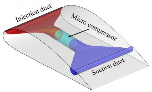
This paper demonstrates the impact of Co Flow Jets (CFJ) on airfoil performance. CFJ airfoils are an active airfoil performance enhancing method which uses injection and suction on the airfoil leeward side. Our research shows that better lift augmentation, higher stall angle and drag reduction is achieved when the injection point of the jet is located close to the point of maximum thickness. This method provides superior performance compared to passive augmenting methods and can be integrated with unified jet-based lift and thrust systems. We analyzed CFJ airfoils based on NACA 2414 by varying location of injection slots on the airfoil. It is essential to give the basic theory behind the working of this performance improvement methodology and to perform 2-D steady Computational Fluid Dynamics (CFD) simulations of the various CFJ airfoils at low speed. The lift, drag and jet momentum coefficients have been obtained from the CFD data and are used to compare the airfoils in this study. The location of the injection slot location is varied to compare performance.

What Co-Flow Jets (CFJ) intend to do? Going towards super-lift coefficients such as those specified on:

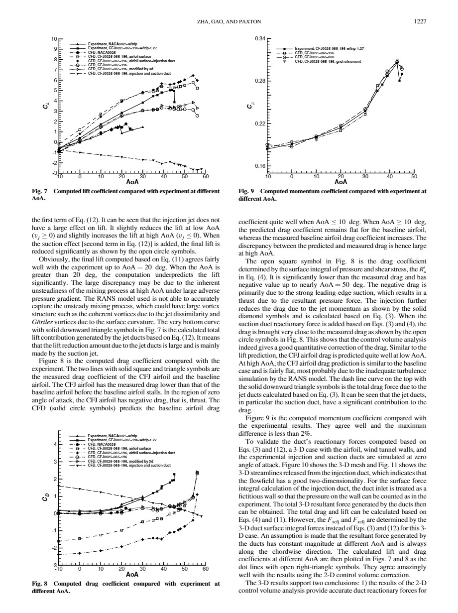
Are there some experiments of Cow-Flow Jets? Below is a paper whose figures 7 and 8 compare experiments with computed lift and drag coefficients (CL and CD).

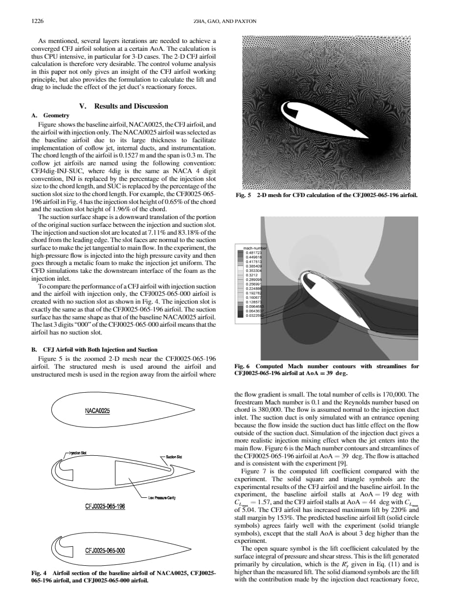
Jet Effects on Coflow Jet Airfoil Performance

Below:

Fig.7 Computed lift coefficient compared with experiment at different AoA
Fig.8 Computed drag coefficient compared with experiment at different AoA

See also:

And:

Why Co-Flow Jets could be interesting for AWES? Let us imagine an airfoil with a lift coefficient (CL) of 8 and a lift to drag ratio of even only 10 without the tether drag, knowing that efficiency is related to CL (CL/CD)²…

2 Likes

I skim read the article, from what I read very simmlar to how dyson fans multiply air flow but for lift. I reckon you don’t even need a pump if it a closed feedback loop. It would be dependent on the size of the ram scoops. From what I’ve seen so far. it a pretty clever design. Ripe for development. I can see many applications especially in scramjet engine design. But also any aerofoil for that matter. Not sure how it could benefit awes or where exactly it would find a home? it’s worth a go, if the pump they refer to? is replace with a turbine of relative size. 3D print a test model would look much like herons fountain. Using the wind to disturb the equilibrium to be completely self sustaining. It a neat idea. Compression ratios will have to be taken into account to ensure a constant, between exhaust aperture and collection scoop. I find it impressive that it has 70 degrees of attack for the monofoil wing structure. That’s near vertical. One to add to the toolbox of tricks. The design reference to boundary layer influences. could also mean a form of low pressure cogging would be involved.

Exhaust jets must be at higher pressure than the collecting scoops.
Choke flow will have to be taken into account as well.
because it’s no use sucking huge volumes of air in. if? the exhaust flow get trapped by incoming airflow from the surroundings. Much how you see rail tankers implode. Technically could be driven by atmospheric pressure alone. provide you calculate pressure differentials. Starting by using 101,325 P standard atmosphere pressure. being the standard unit anything. less than that will generate airflow to fill the void. Much how siphons work. They are able to draw fluids up hill provided the exit is lower than the starting point. I’m intrigued to see where this can go. But it does mean there a theoretical maximum output built in. It should be equal to the incoming airflow minus the usual losses through drag friction and heat. Just something to chew on in the coming months. As new designs emerge. Airborne aeromine comes to mind when I think of this. but in a completely different way I hadn’t anticipated. There option here for variable geometries and polygonal structures. Especially if you consider after burner style mods to the exhaust vents. You will have an induction compression power exhaust design on your hands. The best thing I can think of is the amount of different Materials that can be employed and for cheep. Jaguar used a turbine range extender in one of their electric vehicles. I’d imagine this to work in a similar way.

Experiments, curves page 8: CL = 4.5; CD = 1.2; angle of attack (AoA) = about 36 degrees.

Very good stuff. It does remind me of the Fanwing. These plots I believe assume an external motor/jet engine that provides high pressure and maybe suction. For AWE that would mean an electric fan driven by electricity from a RAT (turbine) or from the ground in case of onboard generation/conducting tether.

For a Makani type of wing this makes a lot of sense. For Kitemill/Ampyx style a little less so because the amount of added complexity and I guess also mass.

In any case, this amounts to a lot of added complexity to an already difficult starting point in AWE. So maybe this is something for 50 years from now if AWE turns out to be a thing

2 Likes

From Super-Lift Coefficient of Active Flow Control Airfoil: What is the Limit? (second paper in the initial post):

Page 6:

The CFJ airfoil has an injection slot near the LE and a suction slot near the TE on the airfoil suction surface as sketched in Fig. 6. A small amount of mass flow is withdrawn into the airfoil near the TE, pressurized and energized by a pumping system inside the airfoil, and then injected near the LE in the direction tangent to the main flow. The whole process does not add any mass flow to the system and hence is a zero-net mass-flux (ZNMF) flow control. It is a self-contained high lift system with no moving parts.

The CFJ airfoil has a unique low energy expenditure mechanism because the jet gets injected at the leading edge suction peak location, where the main flow pressure is the lowest and makes it easy to eject the flow, and it gets sucked at near the trailing edge, where the main flow pressure is the highest and makes it easy to withdraw the flow.

Fig. 7 adopted from [23] is the PIV measured velocity field of the CFJ-NACA-6415 airfoil at the AoA of 25◦ and Cµ of 0.06 , which has the flow attached and a higher speed within the wake than in the freestream. In this case, thrust is generated. The baseline NACA-6415 airfoil has massive flow separation at this AoA. Fig. 8 shows the wind tunnel test results of several CFJ airfoils at Mach number of 0.1. The CFJ airfoil achieves a CLmax of about 5, more than 3 times higher than the baseline airfoil. It also obtains an enormous thrust coefficient of about 0.8. A CFJ wing is hence can be used as a distributed thrust system.

Page 15:

As shown in Fig. 13 for the Cµ from 0.04 to 0.25, the L/D are negative up to AoA about 30◦ . That means the CFJ airfoil will propel itself without a propulsion system. Even when the AoA is near 70◦ with CL about 8, the L/D is at a high level of about 50. This means that the aircraft does not need a large engine and the system can be more optimized to favor cruise efficiency.

Page 29:

The CLmax appears to have no limit. The CLmax limit from the potential flow is the result of imposing Kutta condition, which is necessary for potential flow, but not a true physical condition that realistic flows must satisfy.

The last point (The CLmax appears to have no limit) is particularly interesting for rigid wings or even controlled blades of rotors for AWES, because difficult scaling by area could be replaced by scaling by CL.

The experiments sometimes very partially confirmed the predictions which also were updated later. For now:

For what I know the possible angle of attack (which is connected to a very high CL) is increased from 20 degrees to 40 degrees, without still reached the value of 70 degrees. By the same the CL was doubled without still reaching a value of 9 or 10. Above all the CD at high realized CL value (4 or 5) remains still too high.

The CFJ system could perhaps reinforce the wing structure. I wonder if wind turbines aloft could feed the CFJ compressor of an hypothetical AWES.

Below is a material description of a CFJ system with a picture:

image

1 Like

I’m wondering, is this a new idea?
Are there any airplanes utilizing this?
Seems like a STOL dream.
How much energy does it use, versus how much energy it saves?
On the one hand it has the flavor of “If it sounds too good to be true, it probably is”,
on the other hand, if true, who would want to miss out on such a breakthrough?
Seems like something I’ve seen before - an old idea or a new concept? A breakthrough? Or a big yawn?

Turbosail uses a similar principle:

Concerning CFJ, improving CL would be interesting for AWE if CD is not too high, even if a very high L/D ratio is not required because the tether drag would flatten this ratio.

For the rest, efficiency issues still affect the AWE sector until solutions emerge.

1 Like

A thought I had when I looked at this last was modified Tesla valve
image
as a compound wind/wing structure. As Pierre rightly points out the work done by Ge-Cheng Zha. A single injection port easier to build. But with a tweak I think multiple injections port are possible.
image
image
Manrose flapping vent or an actuator controlled injection vent. A custom built one in this case. Giving and areofoil the greatest amount of flexibility. The same could apply for the suction end. The opening to gather as much volume of airflow from the greatest area possible. From the greatest range of windspeeds. I see no reason why it can’t have multiple turnbine units place at give distances and intervals. 1m*1m aluminium is about £23 a sheet over here. it about the same for acrylic. Might be cheaper to use a reinforce composite. moulded to the wing spars. Something like impregnated canvas. It shouldn’t take 50 years to find out if it works. Heck even concrete would do the trick here. If you can get the cloth thin enough? But with high tensile strength? Spiders silk prehaps? Or aramid fibres? It would be possible to find out sooner. There must be a ratio between intake and injection ports. In my mind, that famous old image of the Ouroboros comes to mind.
image
I’d assume it would run on the square aspect ratio if the diagonal is square routed. Meaning the intake is larger than the injection ports. Plenty of option to go with. Don’t know if you could get a Pratt & Whitney to do the job. But with some funky finagling and a wing the size of a A380. maybe? The infer-structure is already in place. Its barging on price. Ripe for a scale 3D test print. To find out.

From Performance and Energy Expenditure of Coflow Jet Airfoil with Variation of Mach Number page 1758

Figure 5 compares the measured lift coefficient of several discrete
CFJ (DCFJ) airfoils with the baseline airfoil at a constant jet mass
flow rate [16,17]. The DCFJ airfoils in Fig. 5 have different slot
blockages to generate discrete injection holes, and hence different jet
velocity, while keeping the same mass flow rate. For example, the
open slot (black solid circles) has zero blockage. The obstruction
factor (OF; i.e., blockage), indicated after “DCFJ” in the figure
legend, is the percentage of the slot area blocked. An OF of 3/4 means
that 75% of the injection slot area is blocked, and it results in many
small discrete holes for the CFJ injection. Figure 5 shows that the
open-slot CFJ airfoil increases the maximum lift coefficient by about
50%, whereas the discrete CFJ airfoil with OF of 2/3 increases the lift
by about 100%. When the mass flow is increased, the measured
maximum lift coefficient is further augmented, as shown in Fig. 6.
Figure 6 shows all the airfoils generate thrust (negative drag) in the
wind tunnel testing, with the maximum amount produced by a CFJ
airfoil using discrete jets with OF of 3/4. The minimum drag is
reduced by 4000% to an enormous thrust coefficient of about 0.8. By
comparing with the open-slot CFJ airfoil, the discrete CFJ airfoil
needs half of the mass flow rate to achieve the same lift augment and
drag reduction [17]. However, the power consumed by the DCFJ is
significantly higher than for the open-slot CFJ airfoil, because the
smaller holes create more blockage loss for the jets. Nonetheless, the
extraordinary high lift and high thrust generated by the DCFJ deserve
the extra energy cost [17]. In nature, the only system that generates
both lift and thrust at the same time is flapping bird wings. In the manmade fixed wing systems, CFJ airfoils appear to be the only system
that can achieve such effect.
Dano et al. [17] experimentally investigated the energy
expenditure at Mach number of 0.03. Their study indicates that the
CFJ airfoil gains drastic performance enhancement at high AoA for a
low energy expenditure. Additional numerical studies performed by
Lefebvre et al. [23,24] confirm the trends. However, no study has
been conducted to investigate CFJ airfoil performance enhancement
and energy expenditure with Mach number effect.

Still Dr. Zha (and his team in Miami), the conceptor of the Co-Flow Jet airfoil.

Curve at 3:14 for Wind Tunnel Testing of Coflow Jet Airfoil. These tests seem to be more recent (2021) than some other tests related on previously linked papers. CL of a wing without Coflow Jet: about 1; CLmax of a wing with Coflow Jet: 8.6. Negative CDmin: -1, leading to huge trust.

My thought is: go for a CFJ AWES, preferably a fly-gen, or at least wait for more favorable results before taking the step. There is not much to lose.

1 Like

Except is flygen a good idea, even with working CFJ?

I will say a few things about this “co-flow” concept:

  1. It is very interesting and possibly very promising
  2. I’ve seen skeptical comments, possibly accurate, that the forces on the bottom of the loop where the air is moving forward within the wing are not being properly considered or measured.
  3. This concept has been under investigation for 18 years, and related concepts were around much longer. That is plenty of time to have built a model, even at RC model scale. Yet so far it seems the only testing has been in wind tunnels, where maybe only the favorable part of the air loop is being considered and not the rest.
  4. I see aspects of “The Professor Crackpot Syndrome” here:
    a) Seems like it all comes from a single source;
    b) The good professor loves to mix in all his pet ideas into one, (ruining good ideas with bad ideas) so of course you see a canard airplane, electric power with all its extra weight. a million propellers, propellers mounted on the top of the wing, etc. Meanwhile, standard practice is to not ruin the top lifting surface with pylons, use lightweight engines, etc…
    c) seems like they are stuck at renderings and wind tunnel experiments - where’s a prototype? Why haven’t they built even a model-size proof-of-concept or full-scale SuperCub-type STOL plane?
    d) their literature often seems to overstate the capabilities, such as claiming vertical takeoff without tilting wings, etc. yet their simulations use tilt wings.
    To me, it seems they are stuck in the “great news!” point of development where as long as they don;t build a working example, they can keep claiming unbelieveable capabilities.
  5. With capabilities that extreme, it makes no sense that nobody has a flying example at any scale by now.

To be fair fanwing did fly but did not go anywhere I think

Fly-gen and reeling are the two methods having shown some production at hundreds meters altitude.

Ultra-high angle of attack is mentioned in almost all documents.

True, but a more recent claim I saw claimed vertical takeoff and landing without tilting the wings. When I try to look up this concept I find it all coming out of the same place in Florida (Miami) and the same main researcher. Supposedly now NASA etc. are “onboard”. Look, if you have a new STOL concept, it is pretty straightforward to just get a SuperCub like everyone else, and implement your new wing style, show up at a STOL competition, and blow everyone’s mind. It does not take millions of dollars, decades of development, NASA, Whacky canard electric planes (flying batteries) with a dozen propellers located over the wings, etc. That is just dodging the issue by adding endless complication.
STOL competitions are well-established, fun, and relatively low-budget for aerospace research. Most of the planes are built in peoples’ garages etc. There is endless handwaving & happy-talk, and then there is simple “build one and try it”.
For STOL, build one and bring it to a STOL competition, or produce endless Professor Crackpot delays and excuses.

Co-Flow Jet (CFJ) intends to increase the lift coefficient and also the possible AoA, and decrease the drag coefficient. CFJ is not a STOL concept as such, even if it intends to facilitate takeoff.

To me it IS a STOL concept, and I think shorter takeoffs and landing were their main stated goal.
My main point is they should build a prototype, and it need not be high cost, and it could (should) be a lot of fun. I do not see any reason a radio-controlled scale-model could not be built and run in short order. Unless… could it be they know something we don’t? Could there be inherent problems with this concept that allows them to keep getting funded as long as they never try to actually implement the concept? This concept has now been around for maybe 13% of the time powered flight has existed. It doesn’t pass the smell-test at some point that it has never been tried, even in a scale radio-controlled model or low-cost single-seat aircraft. Especially in this era of so many highly-funded (billions of dollars) EVTOL “flying car”, “flying taxi” development efforts, with so many working prototypes.

Increasing lift coefficient and decreasing drag coefficient could be useful for AWES.

Yes Pierre of course that is true.
But like so many topics that sound like “the answer”, where is the proof this is for real, in the form of a working prototype? Are you suggesting AWE should be the proving ground for this concept - that nobody can even build an RC model using this technique, but we should forge ahead and “prove” it with an AWE system, when AWE is in a proving stage itself?
Don’t get me wrong - I love the idea of this concept. I just hope it is for real, as advertised. Seems to me that anything this “revolutionary” would have a working model after 18 years.
Is it possible that it requires excessive power to implement?
Is it possible that providing that extra power adds too much weight?
Is it possible that all the advantages are negated by the forces on the ducting of the return flow?
Is it possible that the weight of all the “pump(s)” is greater than the benefits?
Is it possible that cruise becomes less efficient due to a more dirty wing and excess weight?
Compare it to someone claiming they had a better wind turbine for 18 years but could never build an actual prototype, just had a section of airfoil in a wind tunnel - would you put your money on it? Just sayin’… :slight_smile: