There are some projects using an helicopter-gyroplane flygen device like on:
or gyroplane yo-yo device like on:
SuperTurbine ™ and Daisy use also the lift from tilted rotors.
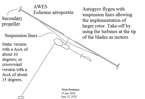
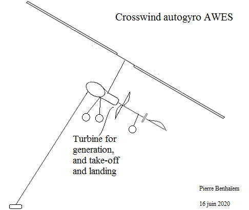
Now the question is if a crosswind gyroplane is suitable, knowing the rotor plane replaces the wing during crosswind operation. After first searches on the web it appears that motor consumption is roughly equivalent for gyroplanes and planes of similar weight.
Below there are two publications about gyroplanes:
Below there is a forum discussion in French language:
https://www.forum-autogire.com/t783-Theorie-du-rotor-d-autogire.htm?start=495 with this interesting sketch below (Cz = Cl (lift coefficient), and Cx = Cd (drag coefficient). The polar gives the values of Cl and Cd for the rotor plane alone in black, then the complete machine in blue) :
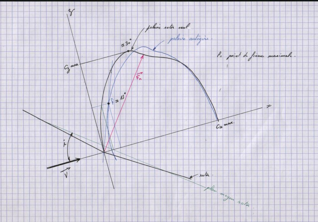
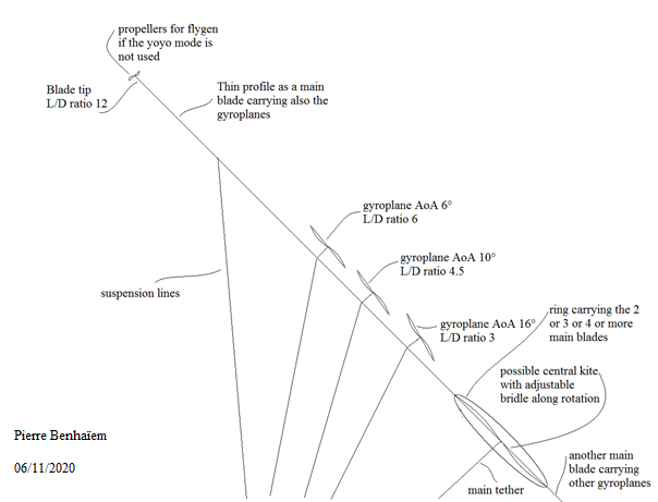
Generally the L/D ratio of the complete machine is about 2.5-4, a little more for the rotor plane alone. However ICAS provides for the MTOsport gyroplane a value of 2 to 16.8 for the rotor plane alone glide ratio for only 2 to 4 for the total aircraft glide ratio, while the speed increases, the difference increasing after 25 m/s. As a first observation it is not easy to extrapolate towards an AWES because both angle attack (relative to the aircraft, 3.2 degrees in the table 1 of ICAS at 33.43 m/s) and angle of incidence (relative to the rotor plane, 13 degrees at 25 m/s in the sketch) decreases while the speed increases, so the Cl rotor plane decreases also. And almost all curves take account of that. However the sketch above mentions the polar in regard to the angle of incidence: it is the reason why it is useful.
So as a first approximation, assuming a wind speed of 10 m/s, we keep the value of 0.45 (from gma’s comment of the sketch) for the Cl rotor plane (55.4 m² for the MTOSport gyroplane as described on ICAS), consider a glide ratio of 2.66 for the complete machine (0.45/0.169 from gma’s comment of the sketch) for an optimal angle of incidence of 13 degrees. In yo-yo mode the crosswind speed is 17.73 m/s (26.6 x 2 / 3 due to reel-out speed = 1/3 wind speed), leading to 15680 W.
As a first comparison, a classical wing covering 1.7 m² like for the area of the blades of the rotor in reference, and with a L/D ratio of 8 with the tether, would generate 9671 W, flying at 53.2 m/s.
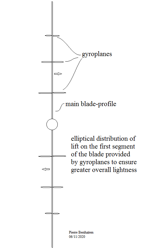
So the crosswind gyroplane could generate a higher value, while its crosswind speed is far lower, allowing less tether drag. It is due to the translation of a far higher rotor plane (55.4 m² for only 1.7 m² blade area against 1.7 m² wing area), even with a low Cl coefficient of 0.45. I do not know if such a system is really steerable, and the cons could be an excess of tip speed, leading to a limit of the crosswind speed even if the wind is very strong, in which case we increase the angle of attack, increasing also Cl, but decreasing the glide ratio.
I see traction use (by yo-yo mode for example) rather than flygen mode. It is because even with a low angle of attack the thrust of the whole rotor plane is significant, while the flygen mode would lead to a flying wind turbine with too large cosine losses in regard to a HAWT.
Beside it ICAS provides a value of 2 for the parachutal drag coefficient for the MTOSport rotor in 5.1 Vertical Descent. As expected this value is far higher than the rotor plane Cl during translation at 13 degrees of the angle of incidence.