FlygenKite

I sketched a TRPT Daisy-like with tied wings on Medium scales for torque transfer systems onshore and offshore - #107 by PierreB.

The problem I see concerns the size of the required rigid tilted ground ring for the generator transmission when the rotor becomes huge.

And also the achievable altitude is dependent to the diameter of the rotor due to the torque transfer requirement.

For a 1 km diameter rotor (it is quite huge but AWES will be competitive when high dimensions (= more or less tether length) will be reachable) such a rigid ground ring would be 0.2 or 0.3 km diameter and 0.1-0.2 km height. It was the reason why I conceived Rotating Reel System.

The limit of a fly-gen flexible wing is its low lift to drag ratio (perhaps 3 at the best with the turbines, and 5 for the kite alone), leading to a low rpm of the generators aloft, something like rpm 1000 for a 2 m diameter turbine (to be compared to the diameter of 2.3 m of the secondary turbines of Makani M600) of TSR about 4 and for a kite flying at 30 m/s with 10 m/s wind speed. The generators would be too heavy when the system scales.

Perhaps one way to drastically lighten the secondary turbines is to install them at the tip of the blades of at least one secondary rotor (TSR about 3 x TSR about 3 of the secondary mounted rotor, so about 9, but not more, rather less). This would give a much higher speed, something like rpm 10.000 for turbines of say 0.5 m diameter.

A use under a static kite is also a (better?) possibility.

A sketch below:

Hello Pierre:
Iā€™m trying to figure out what the lift-to-drag ratio of a supporting kite has to do with the RPM of a turbine?
Also, the idea of enhancing the wind speed through a rotor by mounting it on the tip of a turbine blade ā€œsounds likeā€ a good idea, but the problem wight become keeping that generator cool. There are two ways high winds destroy turbines:

  1. high RPM and gusts rip the turbine apart;
  2. Sustained high output leads to generator heating until the windings burn up the insulation and/or sometimes melt.
    All these ā€œarmchair engineerā€ ideas sound great as long as everything remains ā€œon-paperā€.
    Iā€™ve mentioned in the past, having a visitor - a girl with zero wind or engineering experience, who on the plane ride thought up the idea of putting small turbines on the tips of larger rotor blades. I had to tell her that it is an idea that gets mentioned every so often, and may work OK, but as far as I knew, nobody had ever tried it, and that was maybe 14 years ago?

One big question is: ā€œWhy hasnā€™t anyone tried turbine-reeling on the ground, or blade-tip turbines?ā€ Should they? Are we missing out on the next ā€œbig breakthrough in wind energyā€? Or is there a lesson to be learned here? If these ideas are absurd on a tower, is it possible they are absurd in the air too?
Anyway, just as it would be possible to do kite-reeling on the ground using an unloaded turbine on a tower on rails, pulling a cable as it rolls downwind, then being reeled back upwind, and seeing how much intermittent energy you could extract from the reel, minus the energy used to reel the turbine back in, GE or anyone else could build a tower-mounted turbine with turbines and generators on the blades.
So why hasnā€™t anyone done it?
Well, to start, you want the blade tips to be light weight. Adding turbines and generators at the tips would make that impossible.
I think examining whether any concept would seem ā€œviable vs absurdā€ when applied to tower-mounted turbines can be instructive for AWE.

The higher the L/D ratio, the faster the wing and the higher the rpm.

There are high density generators that work at high rpm, example on

Here the blade tips would be robust.

Peter Jamieson clearly explains the secondary rotor concept in his book page 128.

Doug, I bet that none of the concepts discussed in AWE will have a serious future, be it yo-yo systems, Laddermill, fly-gens, Serpentine ā„¢, and so on. However, there is nothing to stop us from having fun with these concepts, leaving the serious work where it is, in the studies and incremental improvements of regular 3-blade wind turbines.

1 Like

If I had just a bit more spare time I would have done it! :smiley: Another big drawback is the added tower clearance requirements. I would imagine this to be less of a problem on a AWE turbine as the inflow velocity is more predictable/constant.

Anyway: Researchers at DTU were looking for commercial partners to develop this idea further some months ago - so it might happen :slight_smile:

1 Like

About secondary rotors (see also Figure 2, page 810):

I just proposed to use it for a flexible kite flying crosswind at low speed, in order to obtain a high rpm of the tip turbines, so more lightness.

Hey Pierre: Some of the motors and generators that say they can magically produce high output without overheating have not been exposed to the relentless torture of steady-state high winds. At some point, all that heat has to go somewhere.

I checked out the Linked-in link and even commented - flagged it as one more ā€œProfessor Crackpotā€ idea in wind energy (which 999 out of 1000 are). Here is my comment:

This is an idea commonly mentioned by outsiders to wind energy. Like all concepts for increasing the air velocity through a rotor, this one has dealbreaker issues. At a 6:1 Tip Speed Ratio (TSR), these secondary blades would be spinning at supersonic speeds, therefore Helge says to reduce3 the TSR to 2. That means increasing rotor solidity (more blades). But low TSR, high-soldity rotors cannot even approach the Betz coefficient, because if the blades are not at a high TSR, the kinetic energy goes into wake swirl rather than spinning a generator. This is one more ā€œProfessor Crackpotā€ notion that will probably never be built after further scrutiny, and if built, will go down in the history of failed wind turbine ā€œimprovementsā€. Also, adding a lot of mass to the primary blade tips will require greatly-enhanced primary blade strength = greatly increased rotor weight. This is just one of those ideas that ā€œsounds greatā€ to newbies and people who havenā€™t fully thought it through. Nice try, but this aint gonna fly! :slight_smile:

Doug Selsam

They are not trying to achieve high Power coefficient for the secondary rotors. What you are trying to optimise is Cp/Ct => leading to a much lower than usual power coefficient.

You should think of them much more like a propeller than a wind turbine (at least in terms of solidity and TSR). Normal propellers can also reach 90% efficiency if I recall correctly.

My answer:

The tip blades [props] need to have a large pitch otherwise they will be producing lots of drag. In that case they will not provide the aero gearing to make this worthwhile. I will provide the insight to see this: for a fixed windmill, downwind force is essentially free (just make the structure strong enough). For a moving windmill though, drag matters a lot. And the faster the blades spin, the more downwind drag. There, I saved someone millionsā€¦

Its an interesting thought though: are supersonic windmill blades possible?

Apparently not Makaniā€™s millionsā€¦Assuming that secondary rotor drag was a real problem, which I doubtā€¦

There is only one Betz limit, which is that of the whole wind turbine.

Well Pierre, Iā€™ll admit, with two layers of blades, it DOES become a bit of a brain-teaser, and I think these smaller, faster-traveling rotors would still be subject to a Betz coefficient of their own, at 90 m/s, and a TSR of 2, or whatever, but whether we want to invoke Betz or not, rotors need to produce power efficiently, and a low TSR rotor cannot produce power efficiently. It is a matter of momentum exchange versus kinetic energy exchange. MV^2 versus just MV. This is one of many facts about wind energy that I have never seen or heard discussed in AWE circles, yet it is very basic. So now you know. Congratulations. :slight_smile:
Also, crossing over to what Tallak is also talking about - secondary rotor drag: Low TSR secondary rotors will generate less power because the lower-speed blades will just force the wind into a swirling wake, as much as spinning the secondary rotor. That is a waste of power you will never get back. The multi-blade slow-moving rotor acts more like stationary vanes redirecting the flow. You want the rotor to get all the energy, not the wake. A slow rotor leaves energy in the swirling wake. Iā€™m guessing that may translate to more drag, but that doesnā€™t sound quite right for a rotor with a steeper pitch to have more reverse thrust (then again it has more blades = higher solidity) , but I will stick with the fact that a low TSR, high-solidity rotor, such as found on farm windmills, for example, cannot harness as much energy from the same wind as a high TSR rotor. A high-solidity, low TSR rotor is less efficient and cannot approach the Betz coefficient. This is known. And because it is extracting power FROM the air it is not the same as a multi-blade propeller, or even co-axial, counter-rotating, dual-rotor propeller on, say, a giant Russian cargo plane. This fact of Low TSR, High-Solidity rotors being less efficient is one more reason to beware of the claims made by promoters of ducted turbines. Ducted turbines and Makani-style kite-plane propellers end up adding rotor solidity and reducing TSR, which makes them less efficient at extracting energy from the wind flow.

From the PDF above (Top-level rotor optimisations based on actuator disc theory, author Peter Jamieson):
Table 3 page 813:
Design tip speed, (primary) Vt 40, (secondary) vt 160, (unit) m sāˆ’1

Page 814:

Assuming a rated wind speed of Ur = 11 m sāˆ’1, and a relative wind speed for the secondary rotors of 160 m sāˆ’1 [ā€¦]

A short video of a secondary rotor carrying secondary turbines, all being old material, then a photo:

As expected the turbines add a lot of drag. It is understandable why early scientists classified fly-gen (Makani) as drag devices.

The full rotor with its tip turbines is destined for a crosswind flexible kite (FlygenKite). One could perhaps say that it is a double drag (dragĀ²) device.

Hi Doug,

I tried to know more about secondary rotors. I think the issue of blade tip loading is a real problem, as explained in the comment below on https://www.linkedin.com/posts/helge-aagaard-madsen-ba006b93_during-the-last-20-years-we-have-been-thinking-activity-6884416938819280896-le8W/?utm_source=linkedin_share&utm_medium=member_desktop_web :

William Miller, Nextwind Inc.

Nope, not gonna happen, this wind turbine concept is fraught with difficulties, almost all physics related. I have designed and prescribed design refinements to many wind turbines and blade concepts, there is a reason that the industry has adopted a singular approach to blade design, elongation, rotor solidity reduction, and specific power reduction. Adding generators to the blade tips will cause huge loads, how does the blade feather to stop?
what happens when you try to brake this contraption?
lightening will blow the shi# out of the generators?
every lightening strike will require a re-powering instead of a blade tip repair,
you really should have talked to somebody in the business, I moved a few airfoils to the outboard stations of the blade and you should have heard the concerns my peers related

Image de commentaire, aucun texte alternatif disponible

I did a short calculation on this. Now a lot comes down to the glide ratio of the profile chosen for the turbine blades. Of course these can be really high for such a simple shape, but the aspect ratio is of course limited by practical realities. Also, if the blade must work both for VTOL and generation, like for Makani, Windlift and kiteKRAFT, there are even more limitations in design space.

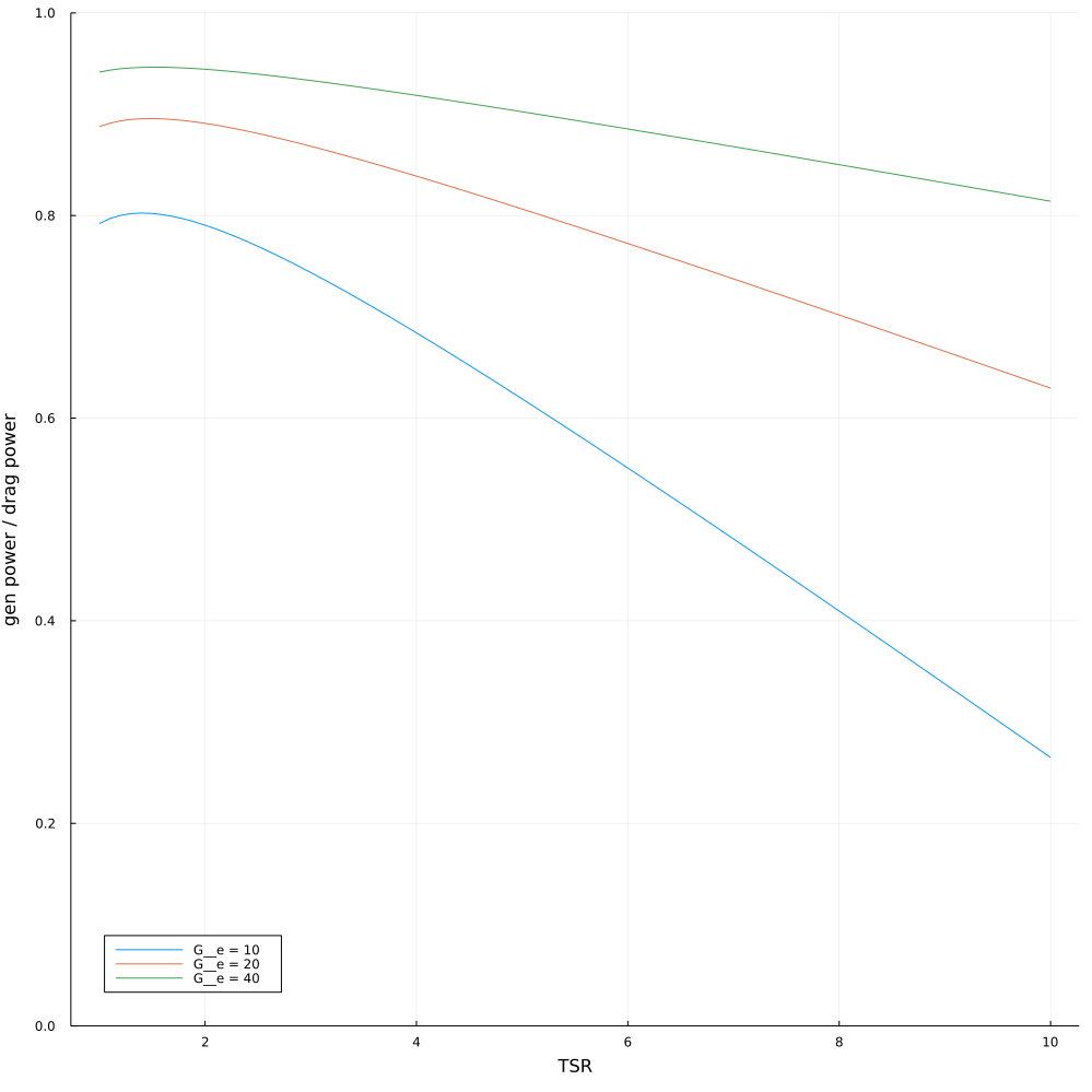
So the plot should show the ratio of power provided to a turbine shaft vs the power in drag direction of the moving vessel (may be a kite, a HAWT blade or a car or whatever). If the ratio is 1.0, the moving vessel will experience the same loss of power as is the power delivered to the generator. Due to what I mentioned earlier, the ratio will never be 1.0, and for some configurations it may be quite small.

It does not take into account that the blades eventually will hit the sound barrier or hit the wake of the other blades and such. So it is an optimistic number.

So even if the main turbine should be like 100% of the energy of the Betz limit, with the ā€œturbine on the bladesā€ approach, some of that is lost there. Also we have additional problems with the turbine blades hitting their own Betz limit and also that the turbine blades are hitting the wake of the main blade.

Note also that where the ratio is very high, the power output is also very small due to low TSR. This means you need to increase swept area to get the power you want. Essentially you can only get a very limited aerodynamic gearing ratio and still some decent efficiency.

Each curve represents a certain glide ratio of the turbine blades. I have no idea what is realistic there.

I will also add the code mostly for my own reference, though I will not try to explain this here and now in more detail.

(maple code)

with(CodeGeneration):

eq1 := alpha = arctan(R / r / K__TSR);
eq2 := (K__TSR * r / R + 1)^2;

eq3 := simplify(subs(eq1, eq2 * (G__e * cos(alpha) + sin(alpha))), assume = positive); # drag power
eq4 := simplify(int(eq3, r = 0..R), assume = positive);

eq5 := simplify(subs(eq1, eq2 * (G__e * sin(alpha) - cos(alpha)) * (r / R * K__TSR)), assume = positive); # lift power
eq6 := simplify(int(eq5, r = 0..R), assume = positive);

eq7 := simplify(eq6 / eq4, assume = positive);

Julia(eq7);

(julia code)

function prop_power_to_drag_power(K__TSR, G__e)
  cg0 = ((-24 * G__e + 3) * log(K__TSR + sqrt(K__TSR ^ 2 + 1)) + ((8 * K__TSR ^ 2 + 24 * K__TSR + 8) * G__e - 6 * K__TSR ^ 3 - 16 * K__TSR ^ 2 - 3 * K__TSR + 32) * sqrt(K__TSR ^ 2 + 1) - 8 * G__e - 32) / ((-24 * G__e + 12) * log(K__TSR + sqrt(K__TSR ^ 2 + 1)) + ((8 * K__TSR ^ 2 + 24 * K__TSR + 8) * G__e + 12 * K__TSR + 48) * sqrt(K__TSR ^ 2 + 1) - 8 * G__e - 48)
  cg0
end

let tsr = 1:0.1:10
  reduce((p, ge) -> plot!(p, tsr, prop_power_to_drag_power.(tsr, ge), ylims = (0, 1), lab = "G__e = $ge"), [10, 20, 40], init = plot(legend = :bottomleft, xlabel = "TSR", ylabel = "gen power / drag power", size = (1000, 1000)))
end

I would like to add, that the plot above does not really support my previous statements that you need a low TSR for a onboard RAT (turbine). For instance, if you have a kite system requiring 500 W continuous onboard power for a system producing 300 kW, you may not care much if the RAT consumes 600 W or 1000 W, taken from the total of 300 kW. Maybe size and generator RPM concerns will be more important. Maybe

@tallakt , I am not sure to understand these two comments. So, as I can, I will quote something I understood before forget it, then you can indicate if that matches your calculation and definition.

https://www.researchgate.net/publication/324565013_Innovation_in_Wind_Turbine_Design (author Peter Jamieson), pages 127-129:

The secondary rotor concept (Figure 6.16) also has potential for very large wind turbine
systems where the conventional drive train solutions will be extremely heavy and expensive
on account of low shaft speed and high rated torque. This concept involves rotors which are carried by the wind turbine blades of the main rotor. The secondary rotors thereby
experience a much higher apparent wind speed than the ambient wind speed and can be of
comparatively small diameter, high speed, low torque and low weight. The idea is quite old,
possibly preceding patent applications of the 1980s and 1990s (Watson [19], St-Germain
[20] and Jack [21]). It has sparked a few misconceptions. One is that the Betz limit will
apply twice to the overall power conversion but, more curiously, another recent one is that
the secondary rotor can achieve a power coefficient of unity [22]. Discounting any ground
related effect, the power produced by a rotor must be exactly the same whether a wind
turbine system is stationary in an ambient wind field of velocity, V , or is mounted on
a vehicle (such as a moving wind turbine blade) and transported at velocity, V , through
still air. In either case the relative axial fluid velocity local to the rotor disc is not V but
V (1 āˆ’ a) where a is the axial induction factor at the rotor plane.
A brief analysis of the secondary rotor concept follows. It is clearly the thrust (and
not power) of the secondary rotor that provides reaction torque to extract power from the
primary rotor. It appears that extraction of power from the primary rotor is most efficient
when the axial induction of the secondary rotor is small. An interesting trade-off then arises
between having larger and therefore more expensive, lightly loaded secondary rotors to
improve efficiency and hence reduce cost of the major primary rotor system.
Notation:
Air density Ļ
Primary rotor radius R
Primary rotor angular speed Ļ‰
Primary rotor blade number N
Secondary rotor radius r
Secondary rotor power coefficient Cp
Secondary rotor power coefficient Ct
Secondary rotor axial induction a

The primary rotor produces power P which is as usual subject to the Betz limit. In terms of
the thrust reaction T of each of the N secondary rotors and assuming for present convenience
that they are mounted at the tip of each blade,
P = NTRĻ‰
T = 0.5Ļ (Ļ‰R)Ā² Ļ€ rĀ² Ct neglecting ambient wind speed compared to tip speed
P = N0.5Ļ (Ļ‰R)Ā² Ļ€ rĀ²Ct RĻ‰
P = N0.5ĻĻ‰Ā³ RĀ³ Ļ€ rĀ² Ct

The power extracted by the secondary rotors is
Pe = 0.5ĻN (Ļ‰R)Ā³ Ļ€ rĀ² Cp
Thus Pe / P = Cp / Ct
Considering the ideal Betz model:
If
Cp / Ct = (4a (1 āˆ’ a)Ā²) / (4a (1 āˆ’ a)) = (1 āˆ’ a).

If the secondary rotor is optimised in its own right, then the usual choice of a = 1/3
applies and the overall limit is 16 / 27 (1 āˆ’ 1/3) = 0.395. This exceeds Betz squared by a little as
(16 / 27)Ā² = 0.351.
However it is much better to trade reduced specific loading, Ct , on the secondary rotors
at the cost of making them a little bigger. In a specific design study a = 0.2 was about
optimum. Hence the ratio Pe/P is (1 āˆ’ 0.2) = 0.8 and the overall limit is 16/27Ɨ 0.8 =
0.474. The power coefficient of the secondary rotors is reduced to a theoretical limit of 4 Ɨ
0.2 (1 āˆ’ 0.2)Ā² = 0.512 and the secondary rotors are somewhat larger and more expensive
but this can be a very worthwhile trade off.

I quote again the main part of his analysis:

It is clearly the thrust (and not power) of the secondary rotor that provides reaction torque to extract power from the primary rotor. It appears that extraction of power from the primary rotor is most efficient when the axial induction of the secondary rotor is small.

Apart from that, a fly-gen wing (Makani-like) does not undergo the structural issue of tip blade loading as for a wind turbine with tip rotors.

I believe he is saying the same as me. You cant have all power lost from the main wing transferred to the smaller turbine blades?