FlygenKite

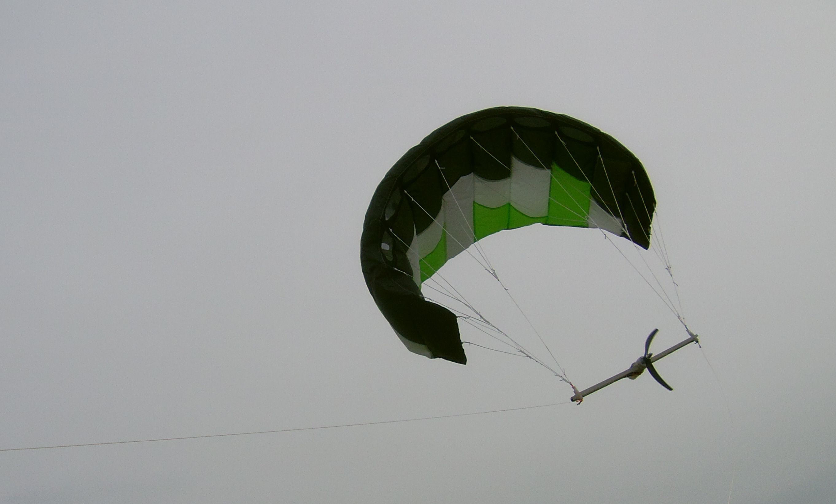
FlygenKite is an old project comprising a flexible wing carrying at least one onboard turbine. It was presented in flight at AWEC2013 and in Kite Festival Dieppe 2012 , the generator feeding a lead tape as shown on the video below.

Some tests were also made with larger generators but without pushing them:

In the calculation the induction factor was neglected as for Loyd’s model. The rotor area should be larger to lead to a lesser induction factor.

Although the paper below indicates:
https://s3-eu-west-1.amazonaws.com/media.newore.catapult/app/uploads/2019/02/21165944/An-Introduction-to-Airborne-Wind-Stephanie-Mann-AP0020.pdf

On-Board Generation
On-board generation devices produce electricity by having added drag on the wing via rotor blades that generate continuously while flying in a crosswind motion (see Figure 3). In this case, the lift coefficient is enough to compensate for the device plus the added drag.The high lift-to-drag ratio requires a hard wing that results in increased performance when travelling across the wind. The power produced on-board is then transmitted down a cable connected to the ground.

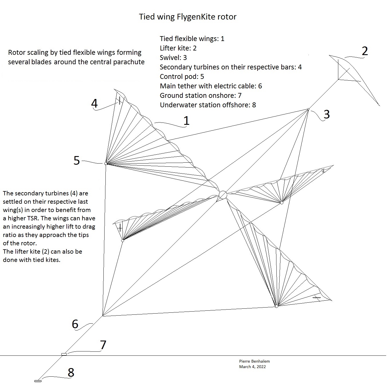
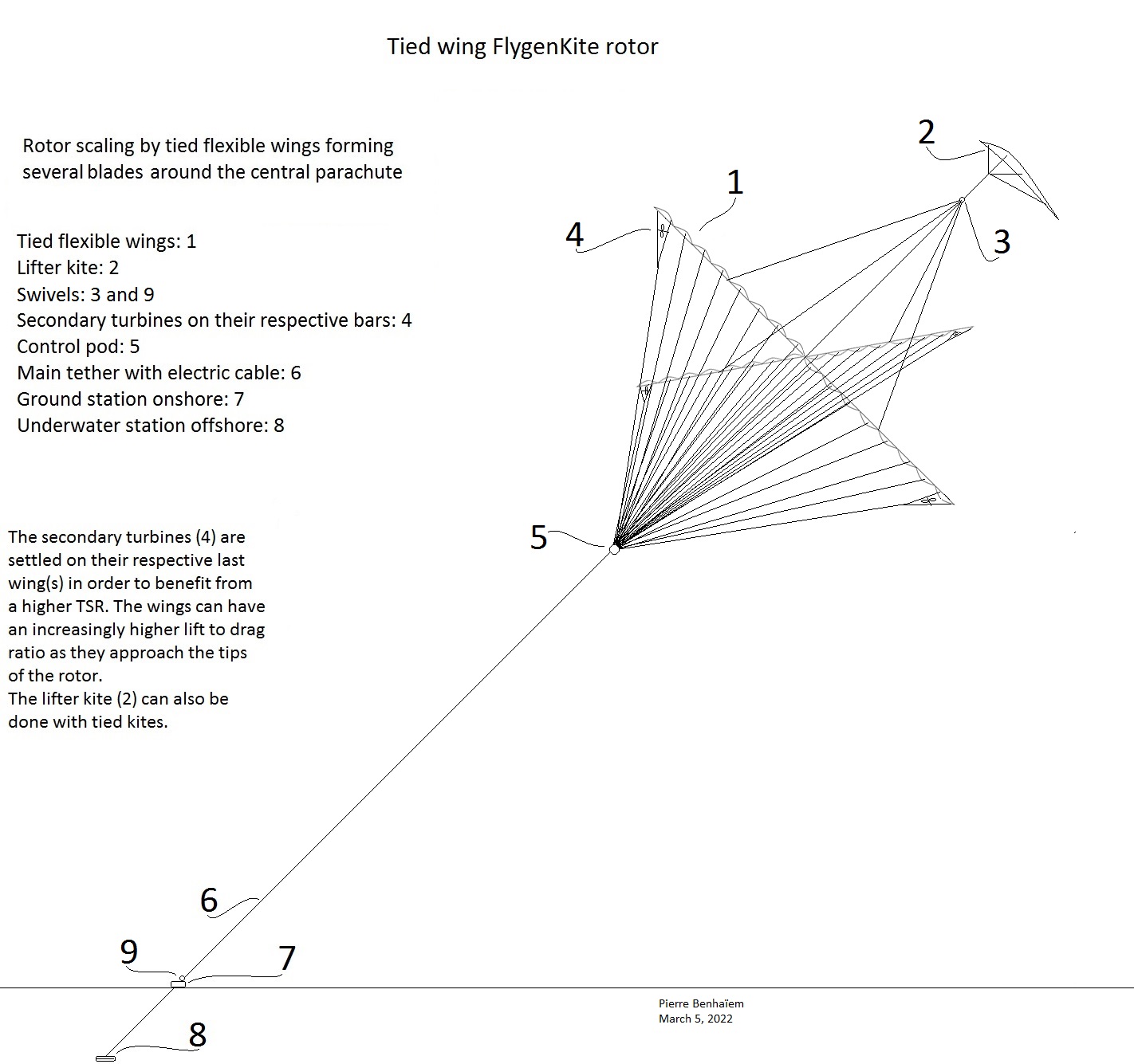
I think a more careful study of flexible flygen could be useful, even if the observation above is confirmed. As for yoyo mode, a flexible wind should use about 10 times kite area to produce an equivalent power as a rigid kite. As an example the expected 600 kW for Makani M600 using a roughly 40 m² wing with a lift coefficient of 2, would be achieved by using a flexible 400 m² kite with a lift-to-drag ratio of 4. An advantage would be a slower flight, so a lower cut-in wind speed. The relatively slow flight could also lead to a better maximization of the space, above all when more scalability can be reached.

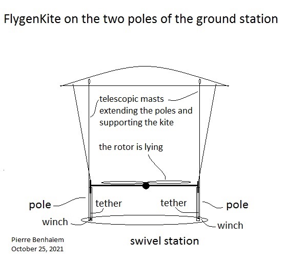
Some improvement of the way to fix the module was and is studied and several options are envisaged.

I think there is an issue with low G_e (lift-to-drag) in flygen. Because the onboard blades are much more efficient if the airflow around them is much higher (i believe though I cant prove it right now). Slower flight equals larger blades, larger generators due to slower rotational speeds etc.

Though I do see that this option may have been underexamined.

Tallak

The point you raise is also mentioned in my post in the quoted publication. That looks to be relevant and I hear the argument of a low glide ratio several times.

However I would want to reexamine that because I saw that the rotor area (33 m²) is close to the wing area (36-40 m²) for Makani M600, as for KiteKRAFT wing. It is a huge value and that leads to relatively large rotors. Loyd’s paper recommended a value of 0.5 for the drag (thrust) of the rotors compared to that of the wing. If the drag coefficient of this wing is even a high value like 0.15, the drag of the (40 m²) wing (without tether drag) would be 6, while the full thrust of the onboard (33 m²) rotors should be about 30: it looks not possible. Indeed with the full rated power wind speed of 9 m/s (data provided by Makani), assuming the speed of flight would be 50 m/s, 33 m² rotors should produce 2 MW. Perhaps (I can be wrong) the thrust coefficient of the rotors should be lower (as well as the power coefficient) as the induction factor is lower when the thrust of the rotors is higher compared to the drag of the wing (see figures 7, 8, 9). See also the relation between axial induction factor and thrust coefficient on


Thank @tallakt for possible explains and corrections about what I just wrote.

A second observation is the limited full rated wind speed of 9 m/s for Makani M 600: this limit can be due to a too high TSR of secondary turbines. As the flight of FlygenKite is slower, it could undergo higher winds, keeping its efficiency, avoiding a too high TSR of secondary turbines.

I think while what I said initially about high G_e is true, it is also true that there are numerous practical issues related to flying very fast like Makani opted for. So I agree that it is maybe worthwhile looking into some less ambitious designs that are more feasible in practical terms.

I dont quite understand your calculations. If the kite has a G_e of 4, you must load it such that the sum G_e with power production «drag» force is G_e’ = \frac{4}{1 + 0.5} \approx 2.7. This allows you to calculate kite speed (around 1.5-2 times wind speed in practice perhaps, no more than 2.7 times windspeed). Next one may calculate how big the drag force of the power producing blades must be in this airspeed. My guess is that for optimum induction factor the blades must be fairly large.

If we eg. consider a AWE like this flying 2x the windspeed, the onboard blades will produce 4x the power compared to a ground based HAWT. This means the onboard blades must be half the diameter of the ground based HAWT.

Such calculations suggest that drag mode AWE works better at higher G_e even than 4.

I do think a glide number for a foil kite could approach 8. With a flying speed of 4x the wind speed, the diameter of the airborne blades would be 1/4 of the ground based windmill. And so on.

To take this to the ultimate conclusion, the blades you propose will be too heavy unless you also use kite blades for the airborne blades. Using something like @Rodread’s Daisy rather than a HAWT like blade should make it possible to increase swept area drastically onboard without a huge weight penalty. In theory of course. Handling should be disastrous

2 Likes

Yes, this is roughly the speed I expected for a kite of L/D of 4 before being loaded by a turbine adding 0.5 drag in regard to the kite drag, leading to: 4 x 2/3.

Not 8x, the airborne blades being 1/4 of the ground-based windmill?

Great idea: difficult but not impossible, as for some other centrifugally stiffened rotor or/and using bank angle for the blades.

1 Like

My reasoning about the diameter if the blades was based on the assumption that they must sweep a certain fraction of the area. So with 2x windspeed, the energy per area is 4x. Then if the diameter of the blades is reduced by \frac{1}{2} the swept area is \frac{1}{4}, and the output energy is comparable.

Do you support your assumption because in Loyd’s formula the L/D ratio is squared (so unlike the real wind speed which is cubed)?

Flying speed (apparent wind) I gather is G_e w (glide number times wind speed). Power is apparent windspeed squared.

The reason I subtract some is due to gravity slowdown, tether strength limit, gusty wind, non optimal flight conditions and control etc. Hard to eliminate all such in real life

1 Like

I am not sure to quite understand your calculation. L/D ratio (where does the apparent wind depend) is squared but the power on the onboard turbine is determined by the cubed apparent wind speed if I am right.

Let us take an example (with some approximations) from the onboard turbines: the diameter of a rotor of Makani M600 is 2.3 m. So 8 rotors lead to a rotor area of roughly 33 m². The nominal wind speed for Makani is 9 m/s. If the L/D ratio is 12, then 6 with the onboard turbines and the losses you mention, that lead to a reasonable kite (apparent wind ) speed of 54 m/s. Air density is assumed to be 1.2, power coefficient is assumed to be 0.2 (losses of efficiency due to a desired lower induction factor leading to larger rotor area; other losses because their trajectory is not rectilinear; other losses…) :

1/2 x 33 x 1.2 x 54³ x 0.2 = a little more than 600 kW.

Now with FlygenKite with L/D ratio of 2 with onboard turbines and losses as you suggest, the same “power” (in fact it is thrust, the real power is that on the wing, even if onboard turbines transmit power to their respective own generators) of 600 kW is captured by multiplying 33 by 27 = 891 m². Too much rotor area, unless I am wrong.

2 Likes

Like how you are laying this out…
When analysing and comparing top level concepts, It’s probably best to keep aparent wind calculation simple.
A fuller analysis of aparent wind contains the true wind vector and is cyclical with the phase of rotation.
I think the Freiburg group proposed a fuller analysis of the changing energy state of pitched rotary wings which could be used later.

The problem with flygen rigid wings of type Makani is the weight as they scale.

The problem with FlygenKite is the weight of the turbines aloft as it scales, that due to a relatively low speed (30 m/s (the double for Makani) with 10 m/s wind speed for a very favorable glide ratio (L/D ratio) of 5).

The problem with FlygenKite with a transmission ring (last sketch) is the complexity for implementation and high speed transmission problems. This has been confirmed to me by several experts including those writing on this forum.

A possibility is using light high density high rpm generators with a gearbox (peak power 1700 W, mass 0.395 kg of which 0.053 kg for the 6.7 : 1 gearbox). Other light high density generators: High speed generators ; Axial-Flux Motors and Generators Shrink Size, Weight (Magnax AXF275 motor (peak 300kW/rpm 8000, continuous 150 kW/rpm 6500, continuous 100 kW/rpm 4000, possibility for a gearbox) about 25 kg); https://emrax.com/ .

So according to my preliminary rough estimations, as the density of generators stops increasing from a certain speed (about 7000 rpm) because of problems such as centrifugal force, we will have a continuous kW/kg density of 4 for soft or rigid wings, but only 3 for FlygenKite because of the gearbox. It’s not a huge difference. It is also necessary to add a few kg because of larger blades for FlygenKite.

As an example a 4.75 m diameter turbine sweeping 17.65 m², would produce approximately 100 kW at 30 m/s (10 m/s wind speed) with a 80 m² flexible wing of glide ratio of approximately 5, weighing about 35 kg. A reasonable tip blade speed would be about 100 m/s (likely less than for faster rigid wings), leading to rpm 400. With a low enough (1 :10) ratio (two-stage) gearbox, rpm becomes 4000, so the rpm of Magnax AXF275 (generator of 25 kg, see above) delivering 100 kW at rpm 4000 in continuous operation. The turbine assembly (rotor + generator + gearbox) would weigh about 50 kg, + about 10 kg for the bar supporting the turbine. We understand that the kite remains lighter than the turbine assembly. It is therefore preferable to significantly oversize it (100-120 m²) to improve performance (in first the glide ratio with the turbine) for a minimal additional mass.

This would remain reasonable compared to a rigid wing of the same power, with the advantage of slower flight and lower cut-in wind speed. In contrast, a rigid wing will not suffer from the effect of moment between the wing and the turbine carrier system.

Take-off and landing operations are facilitated by the rigidity of the bar carrying the turbine. I observed that the kite took off easily manually.

The ground station would comprise two poles for the two ends of said bar, allowing the kite to expand. The turbine (generator as motor) would inflate the kite then allow to assure VTOL take-off, the tilted position of the whole facilitating the catch of the wind ending this phase.

1 Like

Are the two poles part of the kite or anchored to the ground? A sketch would help. Can this method of launch and land be made autonomous?

Hi @gordon_sp ,

The structure of the version of FlygenKite I just described is the same as initially (last photo in my first post).

As I mentioned the two poles are a part of the swivel (facing wind direction) station, and support FlygenKite by the bar.

I think it is possible to automate take-off and landing by using the turbine as motor-propeller directing air towards the kite (which is in downwind position) helping it to rise before catching the real wind. Perhaps an orientable turbine is needed, but perhaps no. Tests would be suitable.

I was probably wrong as the Induction factor is very important for secondary rotors for fly-gen AWES.

A current wind turbine has a thrust coefficient (table 8) of 0.9 at Betz limit. For my initial estimates, I rounded to 1.

So the wing area is 1 m², the lift coefficient (CL) is 1, the drag coefficient (CD) is 0.25, L/D ratio = 4, coefficient cosine³ = 0.65, air density = 1.2, wind speed = 10 m/s. Power: 924 W. The secondary rotor had a CD value of 1, with an “optimal” swept area of 0.125 m², the rotor thrust adding 50% drag to the kite-tether drag as usual.

But I remarked that the rotors of Makani M600 and other fly-gen AWES looked (for me) largely oversized. A main reason is to lower induction factor in order to obtain a better efficiency in regard to the kite potential.

To keep the proportions my initial rotor of 0.125 m² should be about 6 times larger, so 0.75 m², in order to maximize efficiency by lower induction factor.

Note that a static turbine of 0.75 m² with a CP of 0.5 would produce 225 W, so only 4 times less, compared to about 100 times less when used with well sized rigid wings.

I presented a rotor built with tied flexible wings. This method could apply for a FlygenKite rotor. The secondary turbines (4) would benefit from a higher TSR, above all if the used wings have an increasingly higher lift to drag ratio as they approach the tips of the rotor. If a value of 5 or 6 (without secondary rotors) could be achieved, secondary turbines would not be too heavy by using light high density generators.

A sketch below:

1 Like

Maybe calculate the drag of that tether assuming zero kite drag. Quite possibly TSR of 5-6 is not possible with such massive bridles just due to tether drag

Thanks for your contribution @tallakt . You well know tether drag issues. On my sketch the proportions are not applied: above all the main tether (6) should be far longer, the whole being a sort of Y configuration like MAWES or dancing kites but as a full rotor. So the main tether being motionless (as for all Y configurations) the tether drag is mitigated.

That said it is true that the geometry of thin blades made of tied wings imposes an additional tether length. Indeed in “usual” Y configuration the tether between the wing and the main tether attachment point is straight, while in the tied wing rotor said tether makes an angle whose vertex is the control pod (5). I don’t think that the additional length would be very important: it can be calculated according to the span of the blade in relation to the distance from the attachment point to the main tether via control pod (5).

I think this additional tether length could be avoided or mitigated with a more suitable design, like that on the sketch below, where the control pod (5) is directly on the main tether (6).

What I am concerned with is the many tethers close to the kite plane. These will be moving the same speed as the kites. Also as these are at a large angle to the shaft, they must be a bit thicker to accomodate higher tension.

A Y-split is beneficial for Yoyo (eg Kiteswarms), but I feel in this configuration the benefit is offset by the amount of thinner bridle lines.

I am all for bridle lines, but they must be minimal and necessary.

The TSR will be higher than the average glide number (L/D) as your blades extend very far towards the shaft center, like a windmill. Maybe the inner blades may be slightly in front of the outer blades to help the overall TSR.

I think a good place to start calculations is to split your bridle into segments, then multiply their l \cdot d \cdot v_t [length, diameter, tether travel speed, relative to tip speed]. Then compare that to the drag of the kite themselves. If tether drag is a lot larger than the kite drag, expect a large reduction in TSR. And vice versa. To be more specific

\sum \frac{1}{2} \rho C_{D,t} l d v_t^2

For all tethers

\sum \frac{1}{2} \rho C_{D,k} S v_k^2

For all kites

To make calculations concrete assume eg tip speed 100 m/s. Then adjust that speed depending on the placement/radius in the kite looping plane. Use the speed at the center of the tether.

C_{D,t} is probably close to one. For \rho it is customary to use 1.225. The rest are given by your drawing/design/wing choice. I would expect C_{D,k} to be eg 0.1 for a rigid kite, though this is very implementation specific

Anyway, this will give you a ballpark indication whether tether drag or kite drag is dominating.

2 Likes

Thanks for the indications.

The tip wings (carrying the secondary turbines, or in yo-yo configuration although, unlike Y Kiteswarms like, depower during reel-in phase would be too difficult due to the number of tied wings) can be likened to Y dancing kites (like Kiteswarms and some others) by removing internal tied wings.

I think continuous tied wings bring a structural cohesion that Y configuration has not.

Intuitively I think (being right or wrong) that tether drag of tip wings in tied wing configuration would be similar to that of the wings in Y (Kitewarms) dancing kite configuration.

Internal tied wings being slower as they get closer to the center, tether drag decreases also.

Also I have come to believe that TRPT is a strategy superior to flygen for drag mode AWE. Maybe you might look at a soft/supported soft shaft for this construction. If indeed TSR > 6 is in the design goals, this would seem feasible

1 Like