100% efficiency: “If it sounds too good to be true…”
Hi Doug, I think Tallak wrote exactly the opposite. The full sentence is:
I understand that you cannot have 100% efficiency. That also confirms both Jamieson’s analysis and his own analysis.
Yes I was in agreement with Tallak. 100% power conversion from any rotor would be unlikely.
Not quite sure about “double-Betz”, but I would think there has to be some wasted energy - probably a lot, or even most. Maybe some of those “really smart people” we always hear about with their failed wind energy companies know the answer. ![]()
I just tried this:
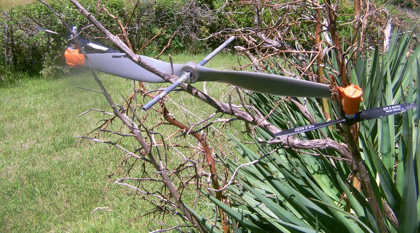
Primary rotor: 0.57 m diameter. Secondary rotors: 0.23 m diameter.
Wind speed: 8-10 m/s.
When the small secondary rotors were facing the wind, they were turning, while the main rotor remained stationary and in profile. But when I placed said main rotor facing the wind, even with it spinning with my additional help, the small secondary rotors did not spin. I think it is because the diameter of the main rotor is too small (less than 3x) compared to the diameter of the secondary rotors which do not attack the wind from the front. I don’t know if this problem is mentioned and calculated, because this issue is not really important when the diameter of the secondary rotors is about 1/10 of the main rotor diameter.
1 Like
This needs to be carefully set up if you want to get good results. The tip props should reduce the speed of the large rotor by 1/3. That is optimum I expect.
For this one, i think using proper blades with correct camber would give rather large benefits. The main blade also needs to be well anchored by bearings to be able to run at high RPM
What you are trying is very hard, and I dare say a bit design intensive.
The 1/3 speed reduction is well known. I already used these small propellers in different conditions, by car with a good efficiency in spite of they are propellers, or to power the leds of a FlygenKite by night, or on tips of a bar I rotated.The small propellers are fixed to a motor with a shaft adapter.
I think the problem I just related comes from the physics, not the propellers as such since they worked in other and different arrangements comprising the FlygenKite module. These propellers were oversized (0.23 m diameter) compared to the main propeller (0.57 m diameter) in such a way (less than 1/3 instead of the usual 1/10) that they cannot produce anything, being not able to take the front wind.
Sure, but they were not available in small dimensions with their suitable generators at the time of the tests. So I used propellers with DC motors for model planes, as wind turbines. It may be unorthodox but it worked pretty well (see measurements).
Yes, but I think that here the physical problem (too large secondary rotors) prevails. I also believe that the propellers at the end of the main rotor destroy the aerodynamics of said main rotor if it is not designed to carry them.
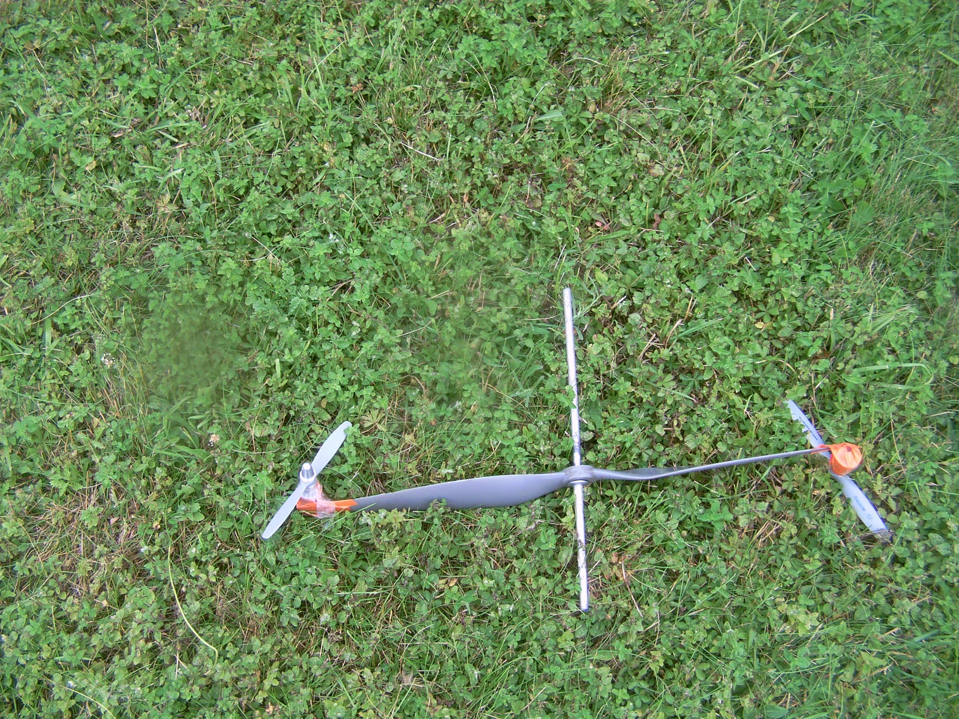
I tried with smaller secondary rotors (0.15 and 0.18 m, see below) for the same primary rotor (0.57 m) and it was not better. Unless the design is specially studied, the secondary rotors destroy the aerodynamic of the primary rotor where the tips of blades were more efficient.
1 Like
In the course of this topic, I’ve sometimes strayed into combinations that are probably not feasible, for the little I’ve tested, like this one: //forum.awesystems.info/t/flygenkite/1401/15.
It is also perhaps a pity that for some reason I strayed towards other concepts that we now know failed. But it is still a bit early to be quite sure, at least partly because failed systems might become successful sub-systems.
That’s why I take back the basic concept of the FlygenKite and whose preliminary tests have been positive, as shown in the videos and preliminary studies: a power kite, at least one turbine, a bar, two lines.
The initial use is as a fly-gen crosswind kite, requiring an automated active control by the two lines at the ground station. Compared to the static version described below, a higher power (perhaps 10x with a glide number of 4 or 5 without the turbines) is reachable, but the high price to pay is a lower elevation angle and a far lower density in the case of implementation of kite farm, so in the end a lower Power to space use ratio.
But it can also be used as a static kite with the same material, the kite becoming a lifter kite. An automated active-passive control is required to stabilize the kite in a stationary position. Higher elevation angle and density become possible, by using more material in return.
Now, I think that the addition of solar power can have a significant advantage for any AWES that becomes ASWES, especially for flexible kites with larger area, and even more so for fly-gen systems because of the electrical cable already present: it saves ground space used for photovoltaic panels, and increases the spectrum of use (wind + solar) and the overall power.
A static FlygenKite would benefit from more sunlight as the sun approaches the zenith.
Conversely, a FlygenKite crosswind would benefit from a better orientation when the sun is close to the horizon.
The materials already exist and are used for sails (French website below):
https://www.solarclothsystem.com/realisations
Premier test grandeur nature en course de panneaux solaires souples (400g/m²)
Translation:
First full-scale test of flexible solar panels (400g/m²)
Classic small and light wind turbines are used, but some other systems evoked above, like TRPT or/and SuperTurbine ™, could perhaps work as sub-systems in order to save some weight.
1 Like
More info (in English) on the same website below:
https://www.solarclothsystem.com/technology
Thin and flexible; all the benefits of solar panels without the drawbacks !
CIGS and aSiGe photovoltaic films encapsulated into flexible and structured textiles providing full protection for the solar modules.
Thin: 25µ à 65µ (microns), lightweight: 210g à 400 g/m2, flexible: can be rolled around a pencil
Reactivity to luminosity: direct and/or indirect sunlight
Sturdy: proprietary encapsulation, product of cutting edge racing technology designed for competitions such as the America’s Cup, the Route du Rhum, the Vendée Globe.
The weight indicated therefore seems to refer to the entire encapsulated photovoltaic film complex, although I am not sure.
A similar technology is described on Technologie ~ Héole :
Le doublement des rendements attendu fin 2022, puis tous les 3 ans vont voir exploser la quantité d’énergie produite et ouvrir la voie à une autonomie complète, illimitée et propre.
Translation:
The doubling of yields expected at the end of 2022, and then every 3 years, will see the quantity of energy produced explode and open the way to complete, unlimited and clean autonomy.
The “Organic photovoltaic cell technology (OPV for Organic PhotoVoltaic)” is relatively new and in progress. The possible supports can be wings, sails, or airships.
A yo-yo AWES could also use it, but by losing the advantage of a not electrified tether.
Launching is facilitated by the bar which supports the turbine and provides some rigidity. Manually the FlygenKite launches in any position, as does the FlygenSharp whose the upper Sharp rotor provides rigidity in the same way.
However, an automated launch would require a support between the bar or upper Sharp rotor and the kite, and side poles between the bar and the ground or along the Sharp rotors to the ground.
I always liked Peter Sharpencil and his Sharp Rotor concept. So simple you’d think it had would be an old. well-explored idea, but no, seems like it has been barely a blip on anyone’s radar screen! ![]()
Pierre, this idea is fantastic, I have been watching this for years, I think we could expand on the idea even more. The issue of launching a foil kite automatically in low wind conditions can be a concern, would you consider three things to make this extremely compatible with the OKE kite winch?
-
What would you say to a ducted propeller? Making it more of a nacelle? (3D printed with ultralight foaming uv resistant ASA) It could also provide protection for the tethers.
-
A slip ring to route electrical power through a swiveling system ($35 on amazon)
-
(This is the crazy idea) Configuring the rotor to be a drone to launch the kite, it only needs to lift a couple of kg for a very short amount of time, and can work with capacitors I have considered using a camera drone to quickly pull up kite and in order to launch
What is invisible to the untrained eye is the stability really comes from the tethers, under tension they are solid. The rotor on the bar is actually supported by these tethers without the need for external control. Also because the tether points are at both ends of the kite, the turning radius is much tighter. More speed, power, and control can be harnessed from the wind.
So my final question is… can they be stacked?
One hundred percent. Just to be clear, once the kite drone is at altitude, it then unwinds? Or is it that the drone acts like a flagpole and the kite is being pulled up like a flag?
Either way, this may solve launching, but have you had any thoughts on landing?
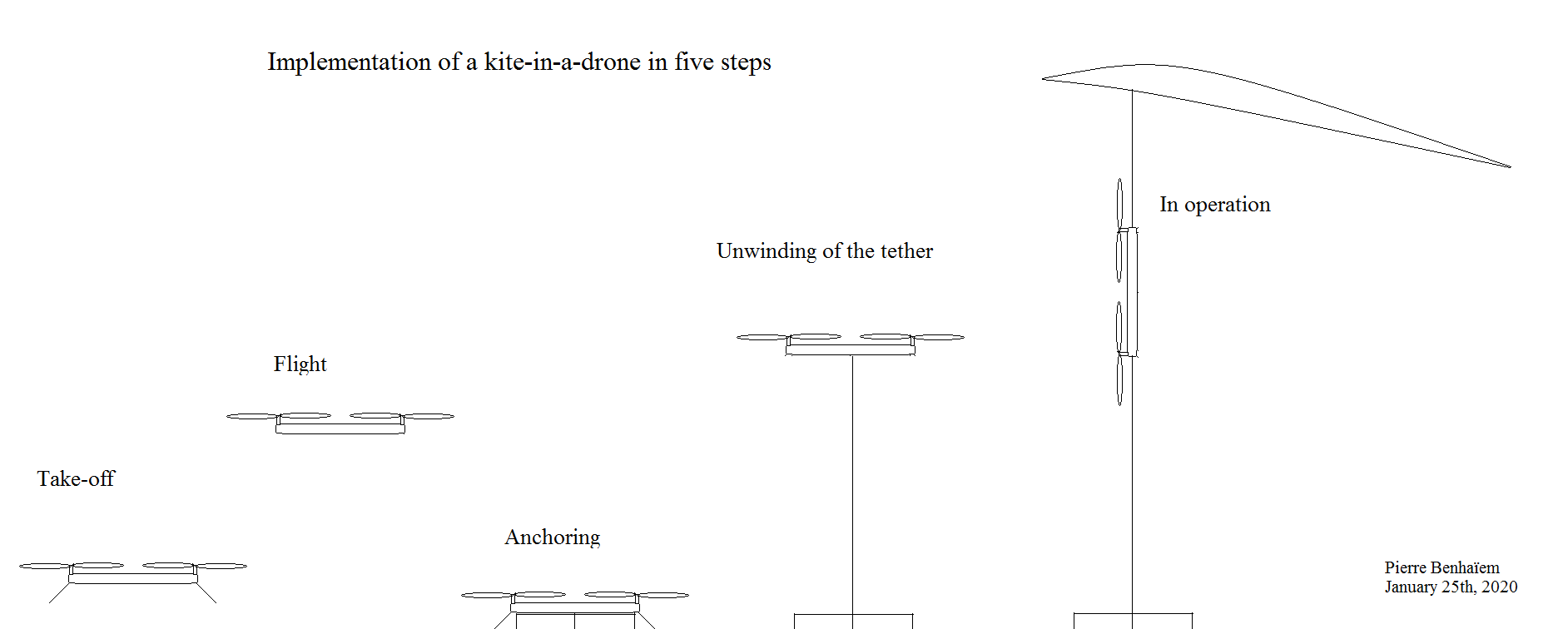
The drone takes off (step 1), then flies (step 2) then chooses a place to anchor itself (step 3), then flies again but unwinding the tether (step 4), then flips his body over at right angles, letting the contained kite escape, the propellers becoming the wind turbines (step 5) as for Makani, the whole being a static (not crosswind) AWES.
The same thing by reversing the steps from 5 to 1.
It’s easier to describe than to do, but it’s perhaps feasible for a robotics specialist, with a fair amount of difficulty.
1 Like
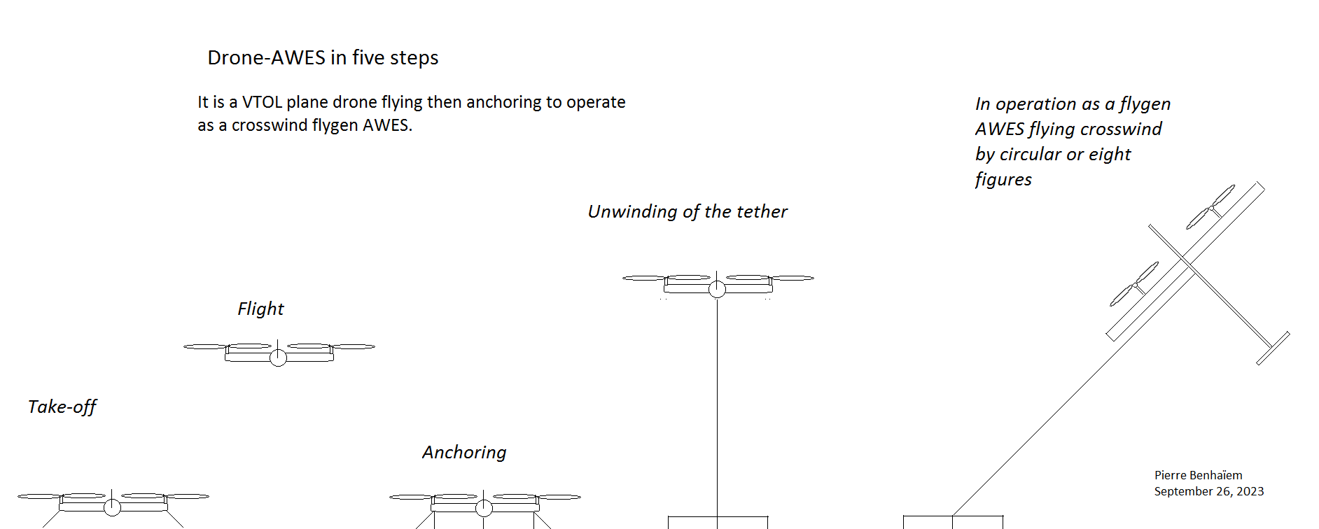
A simplified version: a drone-AWES. It is a VTOL plane like Makani or the VTOL plane on the video below. It flies, then anchors, then operates as a crosswind flygen AWES. Sketch:

The anchoring automated system on these AWE drones 1 and 2 could be based on some kind of screws screwed into the earth, a bit like in the video below:

Nice design for the VTOL drone airplane. ![]()
Hi Doug, some steps to go towards a VTOL drone-AWES plane: a @ChristianH 's idea (“Configuring the rotor to be a drone to launch the kite”), then my idea of “mixing both drone and kite”(see the sketch including 5 steps whose anchoring), then the “simplified version” (the lifter kite is removed and the VTOL drone becomes a plane with the ability to fly crosswind).
A drone version of Kitekraft 2.4 m span would perhaps be a possibility, although very difficult to achieve. For personal wind energy use or various missions, the 2.4 m wingspan is more than sufficient: scaling up is not required, but perhaps scaling down can be.
I think a battery would be required, and would be powered by the plane as an anchored AWES, then discharged in free flight for the various missions, then this cycle is repeated.
For AWE personal use, that would mean the drone would come back to home after battery loading.
To simplify further, if we want to avoid the relatively difficult crosswind flight control, we could base ourselves on https://www.skywindpower.com/ quadrirotor which already looks like any drone like on:
")
See also the new topic: Drone with anchor.
And also a video about drone anchor (here a hook):
Tipula - Drone Anchor Placement

2 Likes
Relevant point.
If managing a Daisy rotor (without torque transfer rings, excepted the ring for Power Take Off) could be simple, it would be a flygen solution for a flexible single line kite controlled by the suspension line control pod like @Kitepower or SkySails.
Otherwise, maybe consider lightweight rotors like the used rotor for
https://kitex.tech/products/wind-catcher?variant=42568574599357
In all cases such turbines could be interesting for flygen AWES being static, or flying not very fast as do flexible wings (20-25 m/s with the turbine for a wind of 10 m/s), as opposed to much faster rigid wings for which even more robust turbines with high rpm generators (and can therefore wear out faster?).