Wind turbines have to be built very strong, or they will be blown apart when the wind gets strong.
Anyone can build a “fair-weather turbine”. But they don’t last. The wind is brutal. ![]()
I thought so. If we go back to our last discussions, this would mean that, one way or another, a kite with one or more turbines on board is unlikely to be viable over the long term. If the turbines are strong enough, their weight is restrictive. If no, the turbines would not be robust enough. And for fast crosswind flygen rigid kites, the power would be concentrated on high-rpm small turbines that are likely to have a limited lifespan.
That’s hypothesis, not an analysis. To test your hypothesis you could do an analysis looking at, say, the work Makani and others have done, what generators were used and their characteristics and so on. I’d be interested for example in the possible cooling effect of an added heat sink moving so quickly through the air, or / and active cooling of the generator.
Yes, it is only a hypothesis. But before considering the solutions, if there are any, let’s try to better understand what exists.
We can wonder if the higher rpm of Makani type (after all barely higher than the 1800 rpm of wind turbine generators in general) limits the lifespan, or if the problem could rather come from the apparent strong wind (but which is also a cooling factor) and the concentration of power on small wind turbines. There is a lack of experimental data.
As a start about rpm of wind turbines:
https://www.google.com/search?q=rpm+wind+turbine+generator&oq=rpm+wind+turbine+generator&aqs=chrome..69i57j0i22i30l2.14103j0j7&sourceid=chrome&ie=UTF-8
What is the rpm of a wind turbine generator?
Large-scale turbines typically rotate at 20 rpm, while domestic sized turbines tend to revolve at roughly 400 rpm . In most large-scale turbines, the low speed shaft is connected to a gearbox. The gearbox increases the rotational speed of the shaft, up to 1200-1800 rpm.
Then a discussion about Makani vs Sky Windpower, Reference: Makani vs Sky Windpower :
Oct 3, 2012 #5 bhaazee 80 0 Ofcourse. If accurate answers are required then actual measurements needs to be made. However, based on working principle I think Makani would provide the best power generated to weight ratio. Coz, the propeller rpm in makani compared to sky windpower is far greater (thnks to the circular flight path in makani). Also, in sky windpower since the device has to hover, I think this limits the unit size that can be built. and regarding the tether, assuming the flight can reach heights of 600 m, what if the flight severes itself (bad wind or mechanical wear…) from tether. The flight can be landed safely. But is it possible for the tether to fall without causing any damage? However, since the airborne wind power is something new, a conclusion regarding the effectiveness, problems, etc. can only be reached after 3 to 5 years of usage.
After more than 10 years, we are very far from 3 to 5 years of usage.
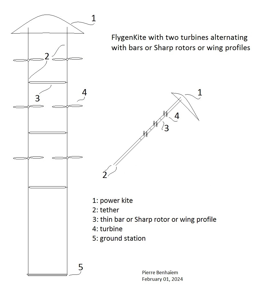
Basic FlygenKite:

Option below.
Replace the bar carrying the turbine with a wing profile generating a little lift to partially compensate for the weight and drag of said turbine.
Superimposed wing-turbine modules could make it possible to get closer to the L/D ratio (around 4) of the flexible tethered kite alone, while carrying more turbine surface area.
Below is a sketch representing an option to carry several small turbines without being too penalized by the mass of the bar, which is used only to maintain space between the two lines. The thin (for crosswind version) bar can be a thin foam Sharp rotor or a wing profile in order to generate a little additional lift. The tethers pass through the respective propellers of the turbines, a little like for Kiwee.
For large static versions, inflatable fatter shapewave® Sharp rotors could be used to compensate the turbine weight.
And also this AWES could be used in both static and crosswind versions, by choosing suitable compromises.
A pair of turbines can be enough, the whole remaining more easily handled.
Pierre,
A couple shotgun questions for you:
If I was interested in making a quick Flygen demonstrator, Do you have any recommendations on how to transmit the power to the base station? Would you do AC or DC? Probably AC (the transformer potentially adds a lot of weight)… is there a place to get conductive tethers?
I think a constant loop cycle with the kite engine would be perfect for the flygen, but then some suitable slip ring would be necessary to avoid twisting lines, Also all of the spools with the conductive elements would need slip rings run through the barrel.
If we could come up with a BOM of this list, I would be happy to test it.
It also occured to me you could have a bot that travels up the line as you have them pictured. the bot could have a couple electronics and a power cable going down, this has been done before.
Hi Christian,
The demonstrator had not electric cable.

I experimented something with a heavy electric cable and a multi-meter, but this did not hold with the crosswind movement.

In all cases DC motors are easier for tests, but heavier and less efficient.
For leds (1st video) I used a small DC motor:
https://product.mabuchi-motor.com/detail.html?id=101
Makani rigid wing used a single electric tether with a swivel. For a flexible kite like mine, avoiding the weight of the pod aloft would be a good thing. For my experiments I used figure-eight.
Perhaps a static use would be better and safer if the weight of the turbines is compensated by the lift of the power kite and the Sharp rotors that are used to space the two tethers and increase the space for the turbines, knowing that the gain in crosswind flight is not very high for flexible kites (about 4-6x, and also taking account of irregular power and quick wear). Commercial wind turbines could perhaps do the trick.
Electric cattle fencing is mostly polyethylene with conductive threads wound through it’s length.
It’s made at scale, so it can be cheap to experiment with.
You have at least 2 lines so 1 +ve 1 -ve
Might need to up your voltage for efficiency.
Also in the same shops they have some good winding spools.
Might help
1 Like
Sorry for the deletion above everybody; I wrote a whole response and forgot that I asked about a demonstrator. I am such fanboy of groundgen that I launched into the potential problems. Has anyone put any thought into long conductive tethers aloft? Do wind turbines experience lightning strikes often? Also using a thin tether, is the only option AC? if so does that mean a transformer or some sort of rectification needs to take place aloft?
Even without electric cable, wet tethers can conduct electricity from lightning strikes.
How to reliably protect wind turbines against lightning strikes
To avoid these damages and costs, reliable lightning protection is needed. Lightning protection systems are used to divert incoming electrical current into the ground, protecting rotor blades or nacelles from damage.
The complete lightning protection system of a wind turbine consists of the external lightning protection system and the surge protection system. The external lightning protection is realized by receptors as well as arresters, which conduct the lightning current into the ground via defined paths.
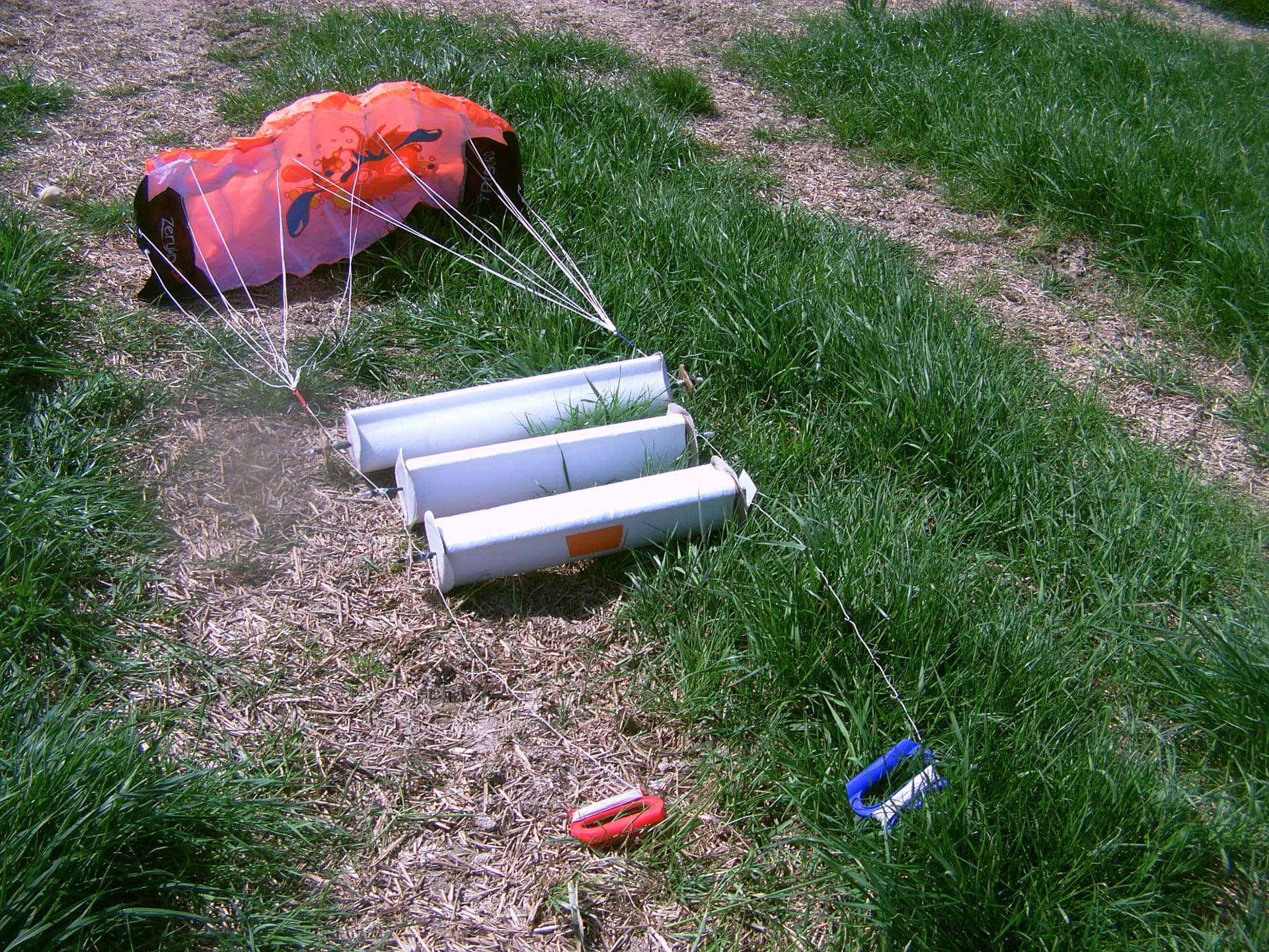
I used DC brushed motors as generators, because the installation was easier, but without being able to test with the kite in crosswind flight, because the wires were torn off too easily. And I measured the power (in W) by using a car, a multi-meter, and the DC motor with the propeller:
However brushless motors and AC are far more efficient (less weight, higher voltage) but required some additional material and are more complex for a first experiment.
Electrical wires can be found at any DIY store.
I did some calculations and I am convinced with todays tech level for conductive wires vs mass, such systems will not scale to many megawatt for one ground station.
Short answer; tether has cubic scaling and at one point the tether shape develops a belly that in turn multiplies the tether drag
1 Like
Makani provided some specifications, including that of the conductive tether. But between what is expected and what is achieved the difference can be significant.
http://www.energykitesystems.net/FAA/FAAfromMakani.pdf
M5 Specs
Rated power: 5 MW
Full rated power wind speed: 9 m/s
Wing mass: 9,900 kg
Generation system: 8 brushless DC motors
Wing
Wing spar: carbon fiber
Wing skin: e-glass
Length: 1,060 m
Tether
Mass: 3,660 kg
Conductor: aluminum
Structure: pultruded carbon fiber
Voltage: 8 kV
Circling radius: 265 m
Operational altitude range: 350m - 650 mM600 Specs
Rated power: 600 kW
Full rated power wind speed: 9m/s
Wing mass: 1,050 kg
Generation system: 8 brushless DC motors
Wing
Wing spar: carbon fiber
Wing skin: e-glass
Length: 440m
Tether
Mass: 250 kg
Conductor: aluminum
Structure: pultruded carbon fiber
Voltage: 8 kV
Circling radius: 135 m
Operational altitude range: 140m - 310m
ChatGPT says: [cut text for briefness, for M600] The weight per meter of the aluminum wire with a cross-sectional area of approximately 33.33 mm² is about 0.09 kg/m (or 90 grams per meter). This calculation assumes the wire is solid aluminum with a density of 2700 kg/m³. In real-world applications, other factors like insulation and manufacturing tolerances may also affect the wire’s weight.
I say: this is the mass of the aluminum core. for the length of the tether, 400 m gives 40 kg aluminum mass. The conpleted tether 250 kg. Sounds right?
Look at the scaling. if we assume M600 at 250 kg tether, the M5 is 2x scale approximately, at 3660 kg. If we would assume cubic scaling we have 250 kg x 2 ^ 3 = 2000 kg. So their actual scaling was even far worse than cubic scaling.
I think though that the power density from m600 to M5 has increased. Quadratic scaling of power should give 600 kW x 2^2 = 2400 kW, and the M5 is rated 5000 kW.
I would say though in hindsight this looks overly optimistic, considering how the flight went.
The preprint Vertical axis wind turbine(s) connected to Flettner or Sharp balloons (DOI:10.13140/RG.2.2.17939.08487) includes a text and a sketch (in the end of this comment) about some combination of Flettner balloons and H-VAWT in fly-gen version, which is suitable for the FlygenKite.
H-VAWT and Flettner balloon(s) of same diameter with generators aloft
This arrangement provides a simplified and more easily maneuverable assembly, and greatly facilitates vertical stacking. On the other hand, this system is adapted to more limited dimensions because it is only held at both ends. In particular it would be suitable for the version of the “FlygenKite” [18 and 19] which uses stacked Sharp [2] rotors as is currently planned (three photos below, before the sketch of the currently planned fly-gen device).
The sketch represents a Flettner balloon and H-VAWT combination. The H-VAWT represented in the Figures 13 and 16 [14) is described above in Scenario 2, and is taken as a basis, considering a different context and a higher aspect ratio. For example if its diameter is 1m, its length is 7 m (7 m²), and the length of the two Flettner balloons together would be 3.65 m (3.65 m²) in order to absorb the complete power of the H-VAWT at a TSR of 3.25. It will therefore be necessary to divide the length of the balloons by three _ becoming 0.61 m X 2 _ in order to allow the H-VAWT to supply the generators with 2/3 of its power, the lower aspect ratio of the balloons lowering their efficiency and their lift coefficient (Cl).
The Fig. 4 [12] indicates a lift coefficient (Cl) of 6. The lift of the 1.22 m² balloons could be close to the lift of (only because of the low aspect ratio) 4-6 m² of kite, so largely enough to carry the generator, the inflatable Shapewave ® [10] blades and the balloons, allowing stacked unities even in crosswind flight where the power would be about (2.5)³ times (the apparent wind speed being about 2.5 times the real wind speed, even with several unities) the power in static flight. The high swept area and the low diameter H-VAWT allow the use of high speed generators without gearboxes, while the high centrifugal force helps to stiffen the blades. And structurally the light inflatable balloons and H-VAWT advantageously replaces the bar [18 and 19] carrying the turbine of type HAWT. The Flettner balloons also serve as supports.


Caption
Fly-gen AWES including H-VAWT combined with Flettner rotors: one unity, then stacked unities, then a kite is added, forming a new (crosswind) version of “FlygenKite”.
1 Like
Caption
Crosswind kite with Flettner balloons and H-VAWT using rope drive transmission.

H-Darrieus VAWT connected to Flettner or Sharp balloons driven by a crosswind kite to increase the swept area
Although the assembly can also be used in static flight, the crosswind flight driven by the kite (not necessarily to scale on the sketch) and the Flettner balloons (both generating lift and drag) can make it possible to multiply the power compared to that of the static flight. The rope drive system avoid the weight and the complexity of the implementation of the generators and electric cable aloft, but its management is difficult.
Update (more details in the preprint, scenario 2) with two sketches:

Although, as such, it is the preferred embodiment (despite or thanks to the relative narrowness of the torus-shaped balloon) for Flettner balloon and VAWT side by side, a FlygenKite version is sketched below:

Just after, I saw a photo of a 22 m diameter “helium-filled torus-shaped balloon” (Figure 1) on:
https://www.researchgate.net/publication/303909318_Torus-nuclear_magnetic_resonance_Quasicontinuous_airborne_magnetic_resonance_profiling_by_using_a_helium-filled_balloon
https://library.seg.org/doi/10.1190/geo2015-0467.1
Although it is not wind energy, the airborne measurement method looks to be interesting, and could lead to some other ideas.
ABSTRACT
The application of surface nuclear magnetic resonance (NMR) measurements, although proven to be valuable for various hydrogeological issues, is in practice often limited to single 1D surveys because measurement progress is slow. First, large stacking rates are necessary to overcome the low signal-to-noise ratio and, second, time and effort are required to move the equipment and to place the measurement loops in the field. We have evaluated a novel approach to cope with the latter. We have assessed and tested a data acquisition scheme based on a torus-shaped helium-filled balloon carrying the loop and moving it rapidly from one to the next measurement position along the profile lines. We have referred to this system as Torus-NMR. We have showed the feasibility of the system to deliver reliable results using common processing and inversion. Surface NMR field data are acquired at successively overlapping positions along a test profile using the Torus-NMR system. To take advantage of the faster loop setup, the overall measurement time of the single NMR soundings is reduced by reducing the number of stacks, whereas the number of soundings is increased to obtain highly overlapping coverage. Regarding a single measurement position, a significant loss of vertical resolution must be accepted that can, however, be compensated to some extent by inverting the complete profile data set simultaneously using a laterally constrained inversion. We have found that for simple subsurface models, e.g., a layered earth with up to three layers, the proposed scheme provided reasonable results, which were demonstrated using synthetic and real field data. We do not expect the Torus-NMR concept to replace 2D data acquisition schemes if high spatial resolution is required. However, we expect fields of application that aim at rapid lateral overview of how specific hydrogeological parameters of shallow aquifers are distributed over large catchment-scale areas.
The basic design:
The impressive results of S1000 prompted me to see if there wasn’t a simpler way to take advantage of the shrouded turbine shape.
With a 40 cm diameter fan, I tested a 23 cm diameter propeller alone, then inside a tire of 42 cm external diameter and 24 cm internal diameter. And the propeller spun much faster inside the tire than alone. My measuring instruments were the sound produced by the propeller, and the pain of the fingers to stop it, with (ouch!) or without a tire.
A tire or a torus (for example the 22 m diameter torus) with a turbine inside, act like shrouded turbines, being far easier to build, and far lighter, with a possible (but not needed) helium or hydrogen option. And a tire or a torus is a protection for the turbine.
In the sketch below, we can see (?) a AWES farm in bumper car mode. Indeed collisions between tires or flexible static kites are without heavy consequence.

We could imagine a tire inflated with helium with its turbine flying alone: it would be a flying tire. But I prefer the lifter (or crosswind in a lesser level) kite, with a tire inflated with air.
Experiment Findings: Flexible kite carrying a turbine within a torus-shaped balloon
- February 2025
- DOI: 10.13140/RG.2.2.29622.00320
Another nice experiment by Pierre: I’d love to see the tire. ![]()