Flettner balloon and VAWT side by side

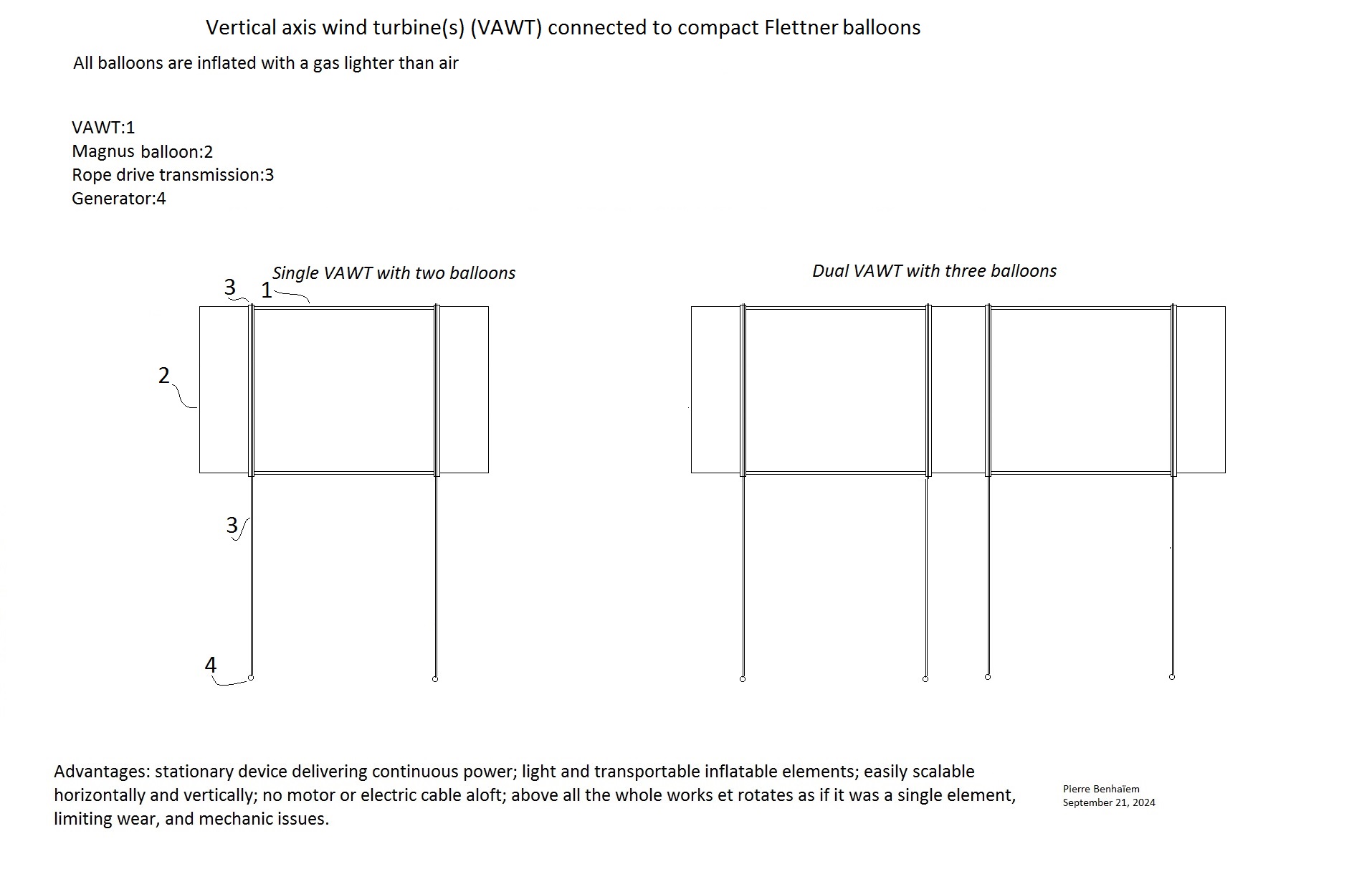
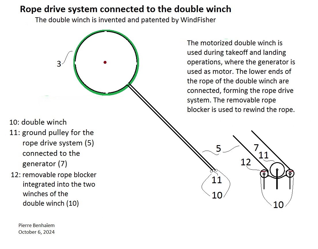
It can be interesting to simplify the AWES when all elements are rotating, working together, and by using rope drive transmission, being stationary. Stacking could also be easier.

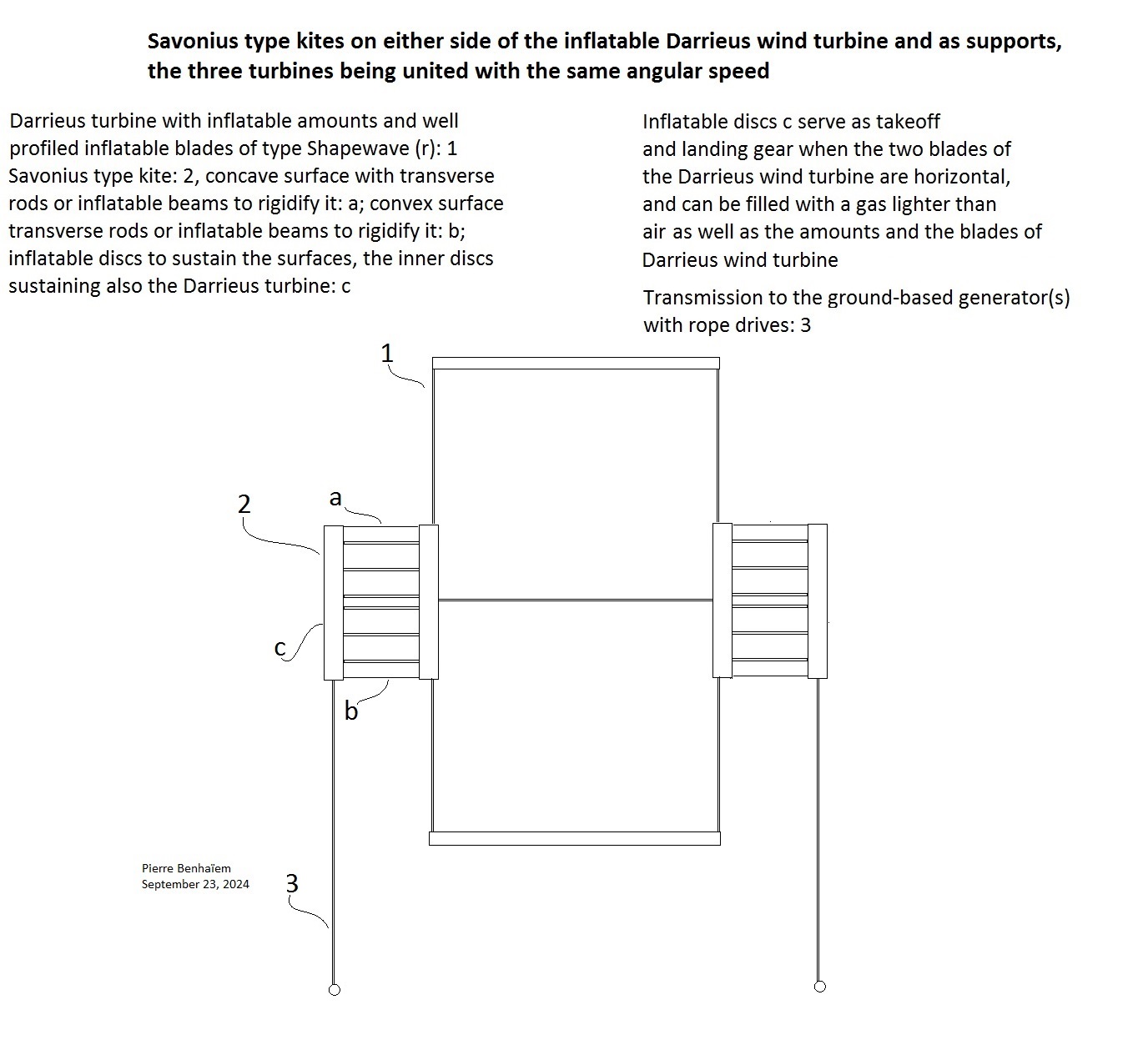
Magenn proposed a sort of balloon surrounded with blades of type Savonius. In this conception the Magnus effect is operating at the tip of said blades, and not at the level of the balloon which “eats” the area concerned by both Magnus effect and the swept area for power generation. And this type of AWES using Savonius blades are difficult to achieve, while being not efficient.

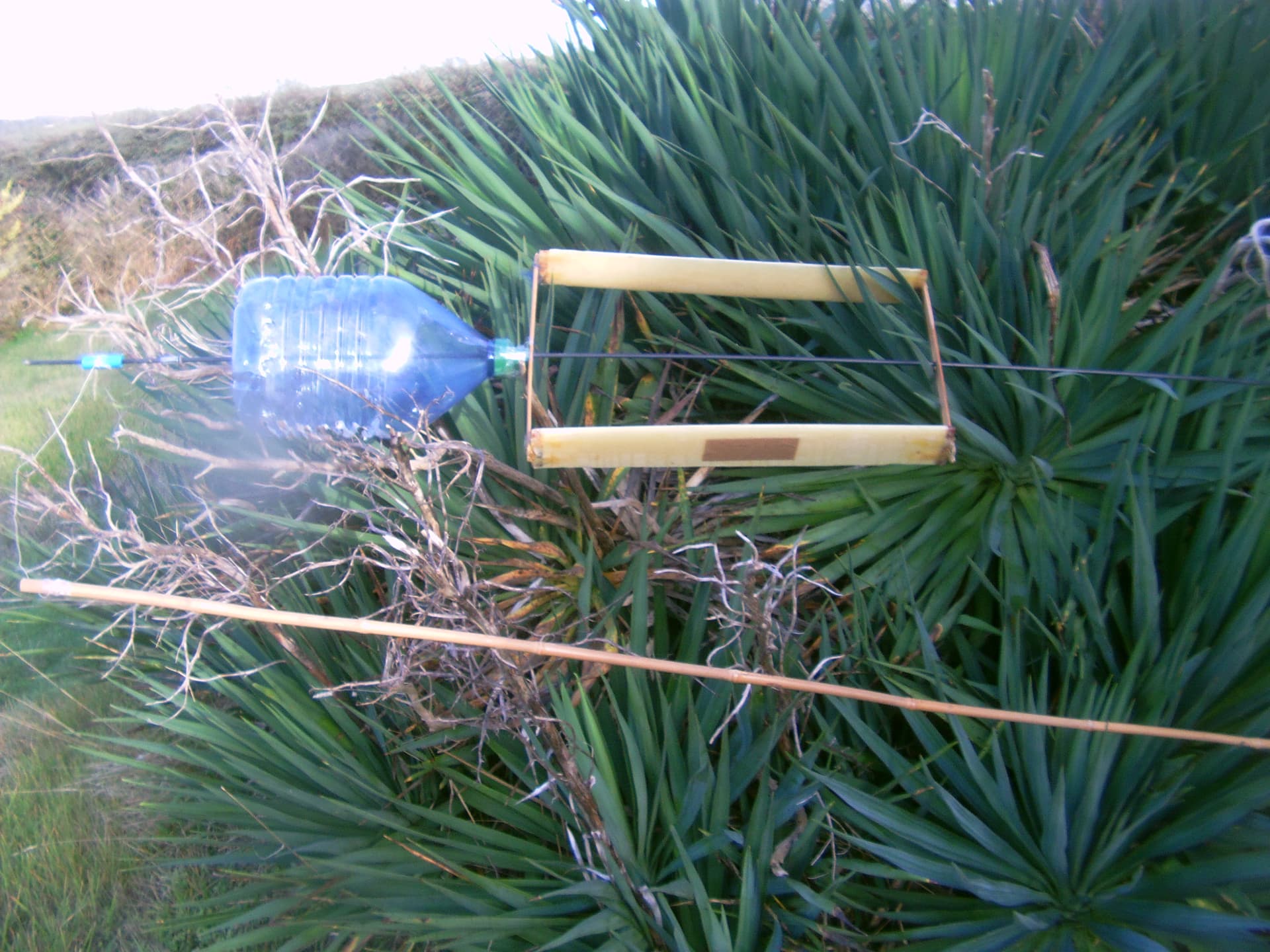
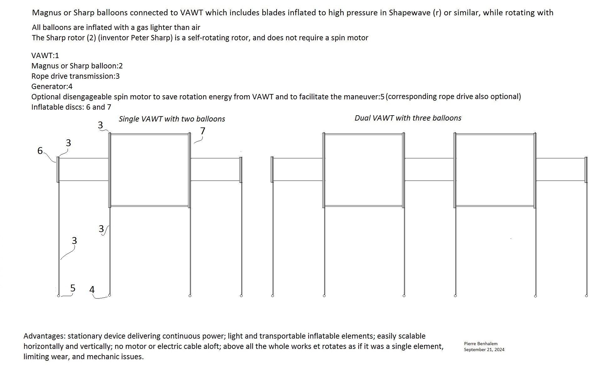
I experimented other configurations such like a Sharp rotor within a VAWT (Darrieus-like). Even with strong wings above 10 m/s, the Sharp rotor did not generate any lift, likely due to interference between both rotors.

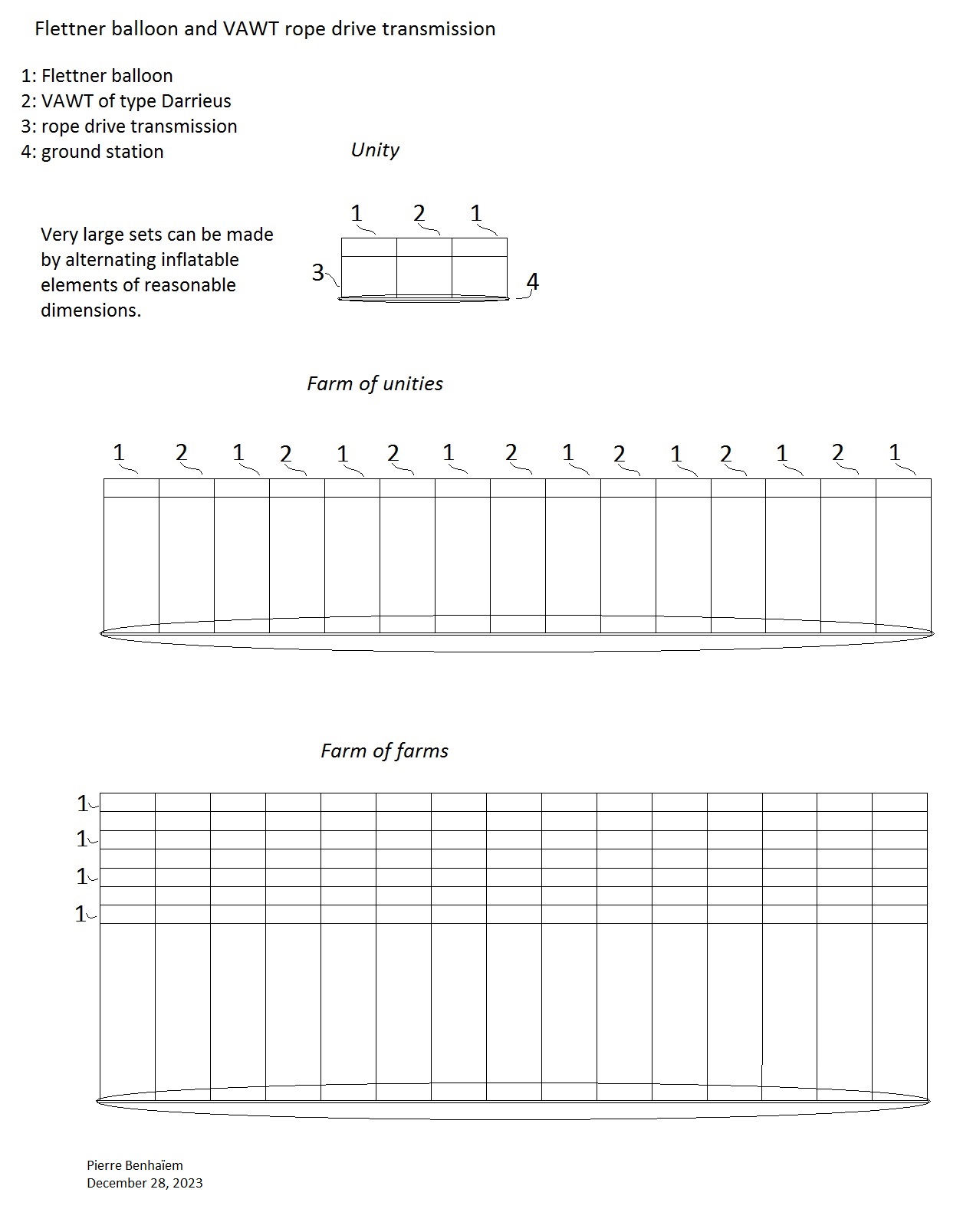
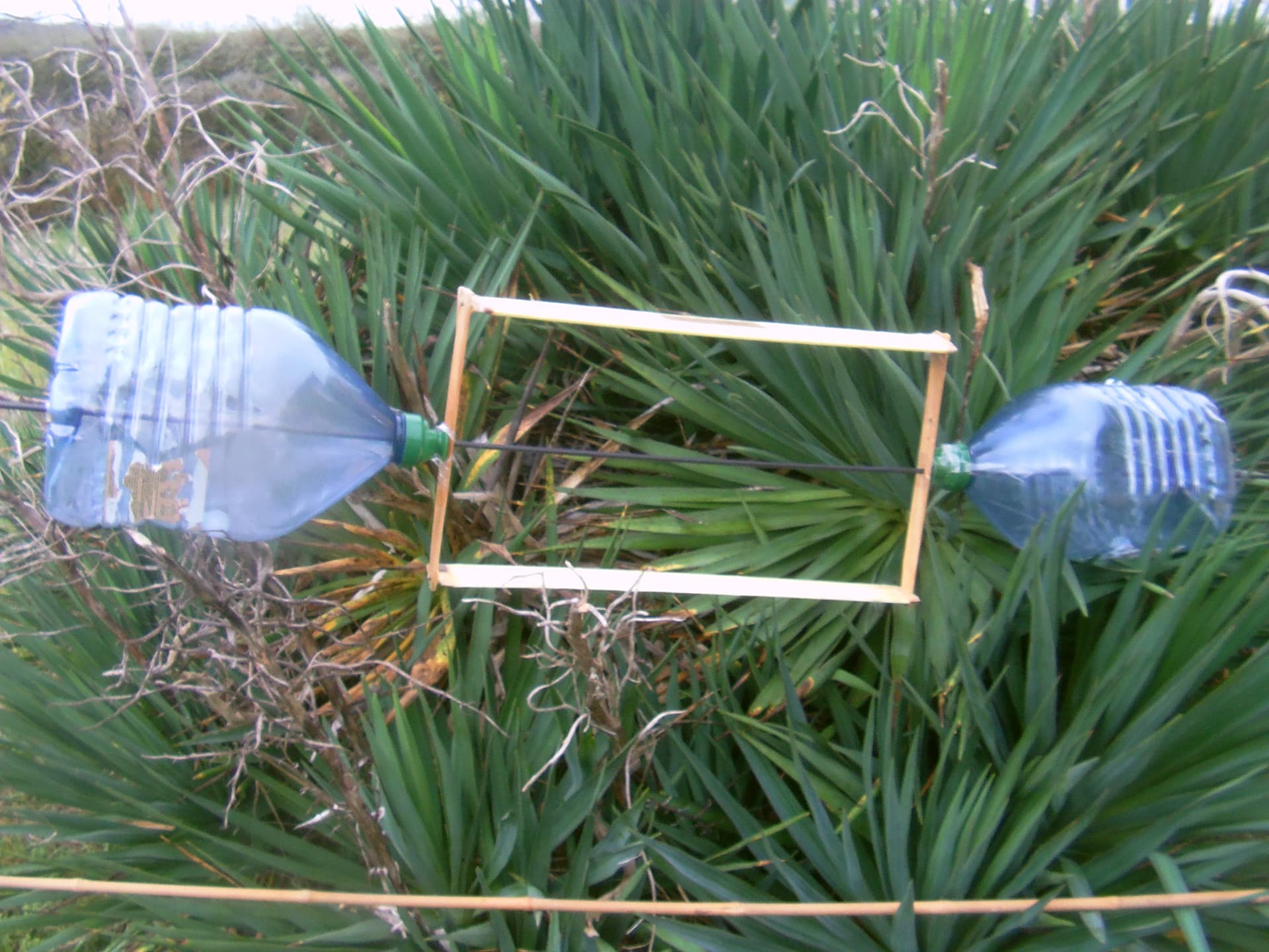
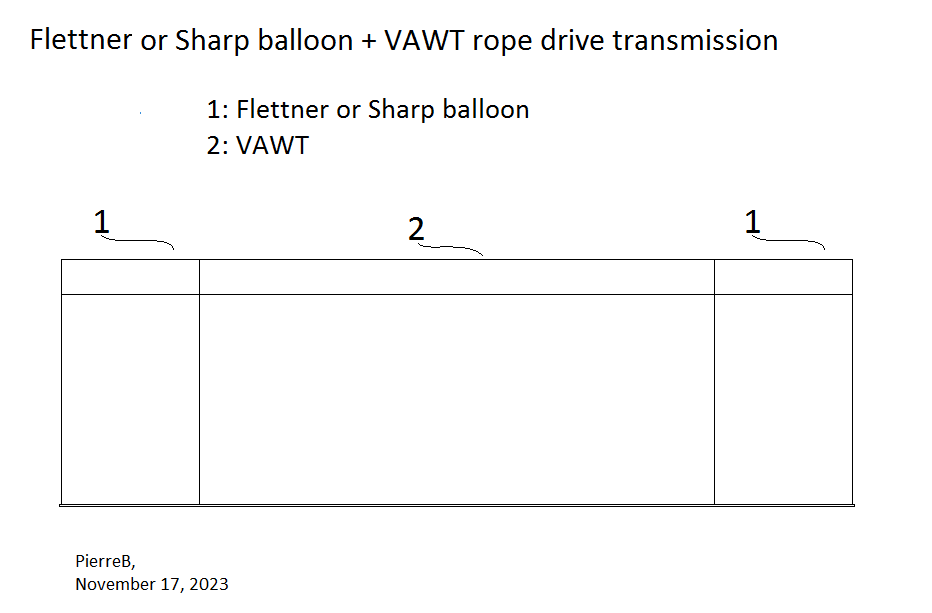
So a side by side configuration is studied. But the maneuver (take-off, landing, then stacking unities close each other) would be far easier if all elements were aligned and of same diameter.

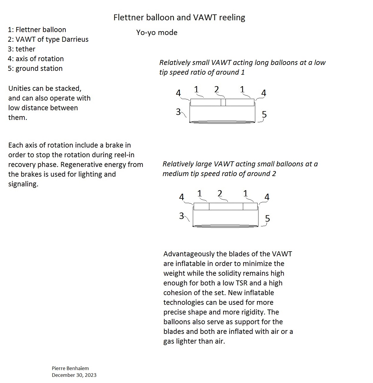
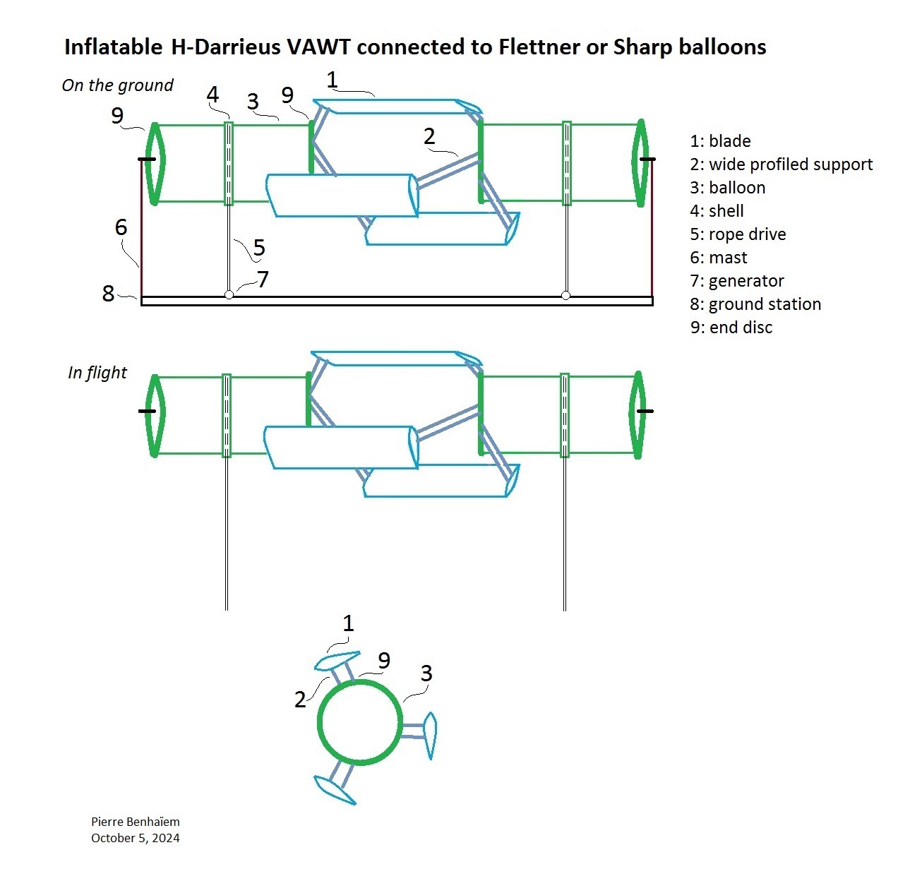
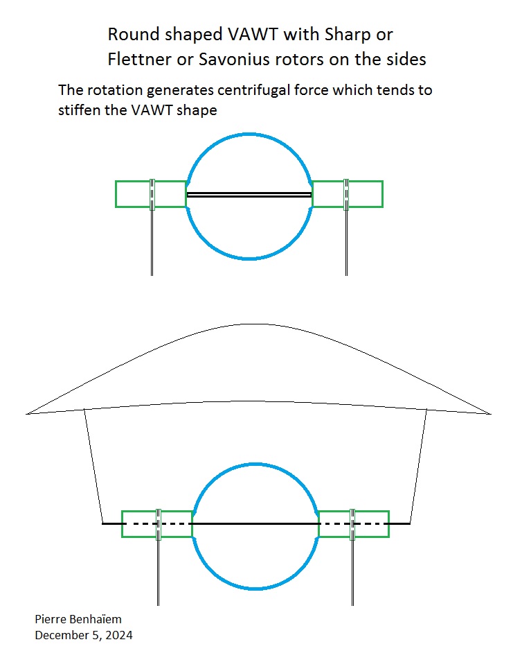
A Flettner balloon is very easy to build and can support the blades of VAWT (Darrieus-like) which can be made by using shapewave® technology. The spin ratio of the Flettner balloon should not be too high, being about 1-1.5. As we know, the power consumption increases by the cube of the tangential speed and would be too high with spin ratio above these values. So the TSR of VAWT should also not be too high, being the same as the spin ratio of the Flettner balloon, leading to a same diameter for all elements.

VAWT Darrieus-like showing low TSR (see Figures 14, 15, 21, and 22) but also high solidity, are studied on:

TSR = 1 or just above with a coefficient of performance of 0.3-0.4 far above that of any Savonius-like rotor.

The high solidity is perhaps not a big issue since for VAWT, the section being the same for the whole length of the blade, unlike the twisted blades for large HAWT, allowing also them to be light by being inflatable and now rigid enough thanks to new inflation technologies.

I put again a sketch as an example:


A Flettner balloon is far easier to build and its power consumption is low for a spin ratio of 1, and acceptable for a spin ratio of 1.5.

See the formula (which I put in full letters) in the last page of the pdf of Experiments on a Flettner rotor at critical and supercritical Reynolds numbers : 0.007 x span x diameter x 3.14 x tangential wind speed³ x air density/2.

An example of an unity, then a farm of unities, then a farm of farms, by using the same two elements alternating, and stackable horizontally and vertically:

The problem with multiple parallel cable drives is that there is no way to ensure that the tension is the same in all of them. If the tension in any cable drive is too low, then it might slip or entangle.

Indeed this is an issue. And also any rope drive could possibly escape from the balloon.

This design was intended to see how balloons and VAWT could be mixed in order to provide lift by Magnus effect.

A yo-yo (reeling, like Omnidea balloon, the VAWT of type Darrieus replacing spin motors) version could also perhaps be studied:

Some experiences last days, using the same 0.52 m x 0.3 m VAWT. The VAWT power is used to spin the 0.2 m diameter bottle(s) which replace Sharp rotors.

Bottle kite:

Rpm 500 in the first part of the video, rpm 1000 near the end, wind speed 8-14 m/s:

Double bottle kite:

Rpm 350, wind speed 10-16 m/s:

1 Like

Great experiment Pierre. Something never done before, requiring no funding, no interns, no new test facility in Ireland, no renting of office space, no director of human resources, no go-fu**-yourself - er, um, I mean “GoFundMe” effort… I don’t see how you could have done this without a few scientific papers, an ample staff, and a dedicated industrial facility! And by the way, I thought you guys were all out of empty space over there in Europe - looks like you have plenty! Looks like a great place to live! :slight_smile:

Thank you for your words Doug. I would add that I will not issue a triumphant press release.

Indeed a VAWT of dimensions equivalent to the Omnidea balloon should be juxtaposed in order to replace the spin motors, taking into account a very high power consumption (much more than the rigid cylinder experienced in this publication).

One thing i noticed: the bottles are pretty short, and if longer, would have a higher aspect ratio, (wingspan-to-chord ratio), which should give more lift, and a better lift-to-drag ratio.

I wanted to experiment with something whose diameter (0.2 m) is close to the height of the VAWT (0.3 m) to have the maximum possible peripheral (tangential) speed and therefore rotational energy consumption (which increases to the cube of the tangential speed). I didn’t have anything else on hand at the moment.

1 Like

Well of course I know you already are aware of this, in general, and I assumed you just used what was on hand and ready for use, which is better than waiting for the perfect bottle, but I just thought I’d mention that longer bottles should give more lift.

It is true. I have bottles with a higher aspect ratio, but the diameter is only 0.1 m. The TSR of my old and patched up VAWT is barely above 1. That means the TSR (or spin ratio) of the bottle would be only 1/3. This is not a good value for an efficient Magnus effect.

I tested thinner bottles with a propeller connected via a bevel gear. The TSR of the propeller was 5 or 6 with the bottles of which the TSR (or spin ratio) was about 1. There was no perceptible lift, unlike the present VAWT with one 0.2 m diameter bottle (spin ratio until 2/3) but also with a far stronger wind.

I reproduce the video:

A preprint: Vertical axis wind turbine(s) connected to Flettner or Sharp balloons, DOI:10.13140/RG.2.2.17939.08487.

Extracts as two sketches with their respective captions:

Basic device, the simplest if the low aspect ratio Flettner balloons produce sufficient lift without excessive consumption due to high speed rotation.

Flettner or Sharp balloons benefit from a higher aspect ratio, a lower spin ratio, and probably a lower power consumption. The construction is a little more complex. Motors (5) installed on the ground rotate these rotors by rope drive transmission (3), thus relieving the VAWT(s) and facilitating maneuvers, particularly takeoff and landing.

A video with Sharp rotor :

Photo corresponding to the video, with caption:

A VAWT in the middle, and a Sharp rotor at each side. This was tested, video [8]. The lift was noticeable although probably weak.

In the section of “description and figures” I added a similar device with the following caption:

Caption

This figure does not appear in the body of the text but the device described is very similar to the other devices and can be appended. The Flettner or Sharp balloons are replaced by Savonius type self-rotating kites which also generate a Magnus effect but also in addition a significant torque. As the VAWT shown here sweeps a large area, the Savonius rotors may need to be longer in order to counter the drag generated by the VAWT. The sole purpose of rope drives is to transmit torque from the combined VAWT and Savonius rotors. The TSR of a Savonius kite can be estimated at 1, and that of a VAWT at 3, perhaps more. Their respective diameters are adjusted, just like the Sharp balloons with their VAWT. The discs are of a much smaller diameter than that of the VAWT which then includes amounts supporting the blades. This provision could also apply to two of the sketches depict Flettner or Sharp balloons with a diameter also much smaller than the diameter of the VAWT, so that the diametrical discs of the VAWT would be smaller and less heavy, the amounts partially replacing for the low diameter discs. A lattice of inflatable bars can increase the rigidity of the VAWT. Usually a Savonius turbine is installed inside a Darrieus turbine to help starting. But such a disposition would destroy the lift of a Savonius turbine settled horizontally as shown with tests using a Sharp rotor inside the Darrieus VAWT. It is the reason why Flettner, Sharp and Savonius rotors are settled externally to the main Darrieus VAWT. During very old tests I noticed that Savonius kites had a good torque, being able to rotate a Flettner rotor of same dimensions, the whole flying. The same applied for Darrieus VAWT with the difference that the Magnus cylinder lifted frankly but the whole thing was unbalanced and did not really fly because the Darrieus VAWT does not generate Magnus effect. It looks that both Savonius and Darrieus VAWT could lead to a successful combination, the Savonius VAWT being settled at each side of the Darrieus VAWT because they generate lift by Magnus effect, in addition to the high torque helping start. All parts are inflatable except for the fabrics inside Savonius kites. A gas lighter than air can fill the inflatable parts. For this arrangement, the elements are light, and the part lighter than air can be reduced or even perhaps eliminated. These devices can also be stacked horizontally.

https://mot-stage.nu.edu.eg/publications/testing-aerodynamic-characteristics-inflatable-airfoil-section

https://ascelibrary.org/doi/10.1061/(ASCE)AS.1943-5525.0001187

Testing of the Aerodynamic Characteristics of an Inflatable Airfoil Section

Authors: Sherif Okda ORCID sherif.okda@eng.asu.edu.eg, Amr Elbanhawy ORCID amr.elbanhawy@eng.asu.edu.eg, Valery Chernoray valery.chernoray@chalmers.se, Wael Akl ORCID wakl@nu.edu.eg, and Adel Elsabbagh

Abstract

Inflatable structures are characterized by being light and easy to manufacture and deploy. Hence, they find many applications in aerospace and aeronautical engineering. In this paper, an inflatable segment with a The National Advisory Committee for Aeronautics (NACA) 0021 airfoil cross-section is designed, fabricated, and tested. The geometrical accuracy of the manufactured inflatable segment is measured using laser scanning. Measurements show that the average normalized error of the chord length and thickness are 2.97% and 0.554%, respectively. The aerodynamic behavior of the inflatable segment is then tested in a wind tunnel at different wind speeds and angles of attack. Lift forces are measured using a six-component balance, while the drag forces are calculated from the wake measurements. The lift and drag coefficients of the inflatable section are compared to those of a standard NACA 0021 airfoil. Finally, flow visualization is examined at different angles of attack using two methods: smoke and tufts. Both methods show that flow separation starts at 15° and full stall occurs at 25°. Results indicate that inflatables can find more applications in the design and construction of aerodynamic structures, such as wings.

Perhaps it would be a solution for the light VAWT inflatable straight blades as aimed above.

PDF availble on request on https://www.researchgate.net/publication/344027702_Testing_of_the_Aerodynamic_Characteristics_of_an_Inflatable_Airfoil_Section

This preprint is updated. A sketch:

Caption:

Preferred embodiment of inflatable H-Darrieus VAWT connected to Flettner or Sharp balloons, with low TSR but good Cp, the great solidity improving the cohesion of the whole.

shapewave® technology would be useful for all elements of H-Darrieus turbine, such like blades and their supports which are profiled. @Rudo, do you have any comments and ideas? About the pressure-class of both blades and supports and their possible weight per m²? Thanks. I would say 1.0 -1.4 bar.

Note that the diameter of the balloon makes it possible to reduce the length of the supports which are integrated into the balloon via the end discs.

1 Like

A post was merged into an existing topic: Wind Fisher

A rope drive can be unwound as seen in the Kitewinder video with the pulley-winch, and until it is completely unwound, not making power. At this time, the rope drive rotates by being driven by the wind turbine hub followed by the right angle return pulley, and drives the generator pulley at the bottom, making power.

The rope drive system is analogous here and generally for the devices described on the concerned topic Flettner balloon and VAWT side by side. The VAWT directly rotates the Flettner balloons which provide lift. And the rope drives transmit the energy from the VAWT via the Flettner balloons. But takeoff by rotation can be difficult without modification of the system. I see roughly what you want to do, and perhaps also what I would like (to be able to takeoff by rotating the balloons-VAWT set before the rope drive is completely unwound, which does not appear on the video).

Answer:

And also winches are adapted to alternating reel-out power phase with reel-in recovery phase, unlike the rope drive which works like a rope without end. “Discontinuous production” would be pumping (yo-yo) mode, where pull is used for power. While with a rope drive transmission the torque of the VAWT is transmitted to the ground via the rope drives around the balloons, with a stationary flight and with continuous power.

Maybe we could use the “double winch drive on both ends of a single cable” like a rope drive (rope without end) during operation, and like it is (double winch) to allow takeoff and landing by rotation. For this, the rope between the two winches should be connected when they are completely unwound.

Magenn was too inefficient (drag system, small blade area, heavy and slow generator aloft) but did not collapse for my knowledge.

A post was merged into an existing topic: Slow Chat III

From the preprint (DOI:10.13140/RG.2.2.17939.08487):

Rope drive system connected to the double winch

A rope drive system cannot change its length during power generation. So the double winch according to the device invented and patented by WindFisher [16 and 17] is integrated into the rope drive system.

The motorized double winch is used during takeoff and landing operations, where the generator is used as motor. The lower ends of the rope of the double winch are connected, forming the rope drive system. The removable rope blockers are used to rewind the rope.

For the same total surface area of ​​the AWES, the yo-yo mode (balloon) generates much more power than the present stationary mode (balloons + VAWT) with rope drive transmission, even in the least efficient oblique base trajectory of the Omnidea type, even more in vertical trajectory (which has a crosswind component and is described in the chapter 13), and theoretically even more by figure-eight with however a considerable loss by power consumption which is a cubic function of the very high tangential speed of rotation.

From my rough (but partially supported by Omnidea’s tests) calculation in “(PDF) Vertical axis wind turbine(s) connected to Flettner or Sharp balloons. Available from: https://www.researchgate.net/publication/384229571_Vertical_axis_wind_turbines_connected_to_Flettner_or_Sharp_balloons [accessed Oct 07 2024]”:

Although other dimensions can be achieved, for this first approach the VAWT is assumed tobe 20 m x 20 m, leading to a swept area of 400 m².Scenario 1 a, concerning the VAWT, the Figure 9 [13] indicates a TSR of 1.6 for a maximal Cpof 0.32, the solidity value being 0.915. The diameter of the Sharp or Flettner balloons is 12.5m for a TSR of 1, their span being 20 m per balloon, and 40 m for both balloons, for a global projected area of 500 m²

Power consumption: about 3 kW at 5 m/s wind speed,and about 24 kW at 10 m/s wind speed. So the total power becomes respectively 6 kW and 48 kW.

So 900 m² for 48 kW at 10 m/s wind speed, leading to about 53 W /m².

From my rough (but partially supported by Omnidea’s tests) calculation in “(PDF) Towards a gigantic Magnus balloon with motorized belts. Available from: https://www.researchgate.net/publication/371856926_Towards_a_gigantic_Magnus_balloon_with_motorized_belts [accessed Oct 07 2024]”:

Extrapolation with a 10 m/s wind speed and the same spin ratio of 1.21
Everything is multiplied by about 6.35, and the power for a classic oblique trajectory before motor consumption and deduction of the transition phases would be around 222.25 W/m²,i.e. a total power of 8890 W before deduction of the consumption power at the tangential speed of 12.1 m/s, i.e. 2222.5 W on average (55.5625 W/m²), and the assumed losses of the transition phases, i.e. 317.5 W, which gives a net average power of 6350 W, i.e. 158.75 W/m².
For a vertical trajectory, the total power would be 16497.3 W, i.e. 412.4325 W/m², which is comparable to that of the flexible kite Mutiny flying crosswind and having a projected area of 18 m², generating an average power of 5.19 kW (table 8 page 44) [4] at a wind speed of 8 m/s, i.e. 323 W/m², leading to a possible 450 W/m² at a wind speed of 10 m/s.

In return we would perhaps have peace of mind (it’s not certain) with the stationary system as described on this topic.

I think the vertical trajectory as described in the chapter 13 would be a good option for Wind Fisher, avoiding a possible excess of power consumption by the cube of tangential speed of the balloon. The vertical trajectory of a rectilinear balloon allows to maximize the use of the space.

Updated preprint:

Trosposkein or round shaped VAWT

These are known forms of VAWT. They can gain another advantage from the use of lightweight inflatable materials through the use of centrifugal force [22] which tends to stiffen the shape as long as the angular speed is sufficient.

Experiments seem to have shown that a Sharp rotor (and probably also a Flettner rotor) inside a VAWT [23 and 24] does not produce significant lift and slows down the VAWT. This is why the central inflatable beam should be narrow, or replaced by a carbon or fiberglass rod. So Sharp or Flettner or Savonius rotors are settled on the sides, and can be inflatable, possibly with a gas lighter than air, just like the blades, or foam (under the crosswind or static kite).

WILLIAM GENE ROESELER is the inventor of the rotor shaped by centrifugal force: