Would it be advantageous to have 2x kites above stretching out the beam to the sides and up?
1 Like
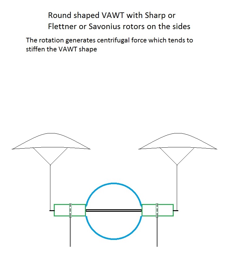
I think you are talking about the first sketch without the kite (the second sketch being an adaptation of the FlygenKite).
It may be advantageous to be able to stretch the central beam, or to make it thicker and in the extension of the two Flettner balloons on the sides, but at the cost of a loss of performance of the central VAWT.
Therefore the proposed solution of a (static) kite on each side would be a good idea to carry out for very large units. In the other hand that could solve the lift issue (if we don’t want use hydrogen or helium) but perhaps not side stretching.
This is the publication I was looking for, and which could explain one of the reasons why inflatable blades are not used for wind turbines, as are inflatable wings for airplanes with some exceptions. The explanations are logical and easily understandable, and give a negative view to the whole topic.
From Abstract:
As the flow speed is increased the aerofoil deforms significantly around its trailing edge, resulting in a negative camber and a loss of lift. The loss of lift is ameliorated by increasing the inflation pressure but at the expense of an increase in drag as the aerofoil bulges into a less aerodynamic shape.
Page 11 (and figures 3 and 4):
This loss in lift remains relatively small for low flow speeds U∞, while for U∞ > 10 a more severe loss of lift occurs, with the aerofoil achieving less than half of the lift of the corresponding rigid aerofoil.
While this value is relatively high for a simple elastic material, the stiffness is increased for aerofoils constructed with composite materials [3] or inflatable panels [7].
That said, the problem of deformation would tend to decrease as the profile size increases. We can assume that for considerable dimensions, and with a relatively low tip speed ratio (TSR), the deformation would be limited, and the efficiency closer to that of an equivalent rigid profile.
1 Like
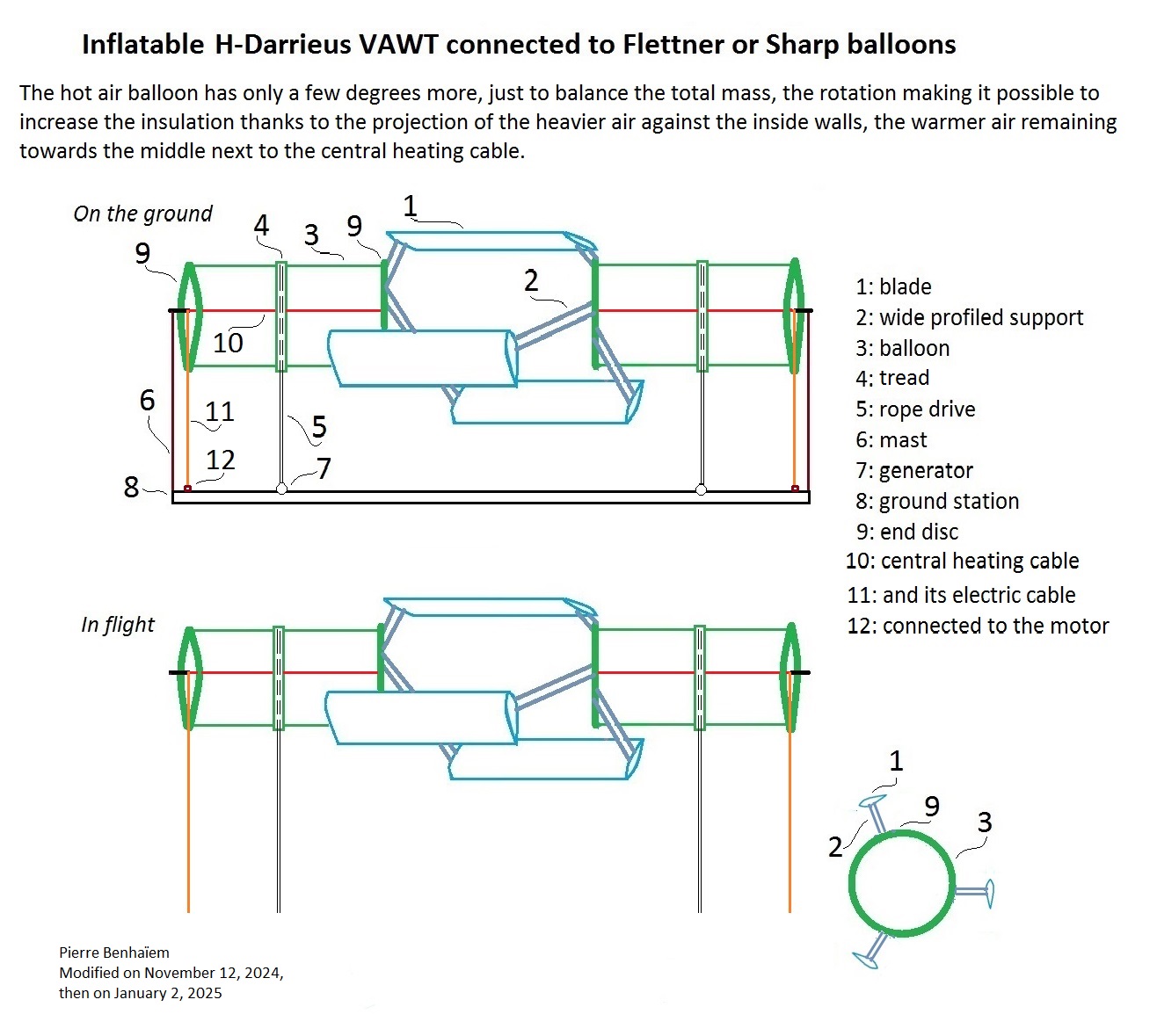
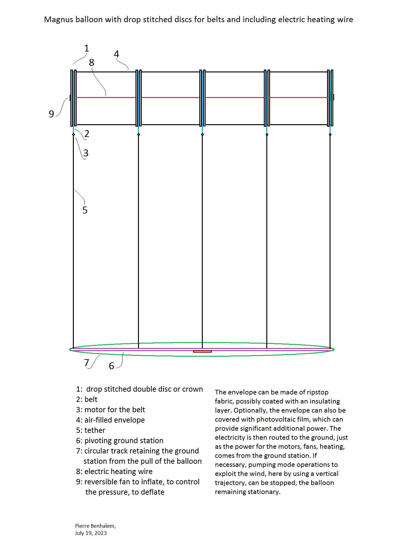
I made a rough comparison between Flettner balloon and VAWT side by side (rope drive transmission, sketch 1 below, preprint) and Preprint: Towards a gigantic Magnus balloon with motorized belts (yo-yo mode, sketch 2 below, preprint).
From Chapter 12: balloon 1000 m² (80 m span, 12.5 m diameter), swept area 13940 m², wind speed of 10 m/s, Cp = 0.157.
The power would be 1.313 MW, so 1.313 kW/m².
Giant balloon 1 km span, 0.2 km diameter, 0.4 kW/m², 80 MW, Cp = 0.0478293, swept area 2,788,000 m², 2788 m in height, by keeping the proportions. Wind speed = 10 m/s.
Now 2,788,000 m² of stacked VAWT + Flettner, totaling 1000 m span, with (per unity) 333 m x 333 m for the central VAWT, and 208.125 m diameter and 333 m span for each Flettner balloon. Cp of VAWT being 0.3, but only 0.2 by being optimistic (with not too high wind) due to the loss of lift by deformation of the inflatable profiles, then 0.06666 if we take into account of the Flettner balloons that produce nothing but ensure lift. So we have 13.3 MW with a Cp of 0.2 on the VAWT of 333 m x 333 m. If we don’t take the requirement of spacing between unities, we have 2788 / 333 x 13.3 = 111.13 MW. It would be less with spacing between unities.
The yo-yo mode seems to be more interesting because for an almost equal power for a same swept area, far less material is used. In addition, the VAWT + Flettner balloons combination has unknowns (real Cp of inflatable blades?).
Omnidea tested yo-yo Magnus balloon, but not in vertical trajectory which would be more efficient.
An example of peripheral drive intended for yo-yo giant balloon.
That said this is not enough to compete with HAWT.
In the case of cable drive, I am concerned that there is inadequate tension to operate satisfactory. Can you give me details on the drive velocity as well as the tension in the cables on either side of the drive pulley? What mechanism do you have to retract the device when the cable is in place? Are you using the Kitewinder system, where the cable drive is stopped and both cables are wound up together to retract the device?
In the case of yo-yo operation, can you give me details on the belt around the cylinder which must slip without friction. Would it not be better to have an attachment to the shaft at the end of the device where a small bearing can be used?
Indeed it can be an issue. Tests are needed, but this architecture has other issues.
No. From the preprint:
Now holding the balloon by only the two ends is not sufficient for large scaling.
External motorized belts in order to hold the balloon on its whole length, and allowing scaling a lot: proposed solution
The balloon is held both by the periphery and on its entire length with as many belts and tethers as necessary. The belts are wide in order to cover more area on the balloon to better distribute the wind force.(4) (PDF) Towards a gigantic Magnus balloon with motorized belts. Available from: https://www.researchgate.net/publication/371856926_Towards_a_gigantic_Magnus_balloon_with_motorized_belts [accessed Jan 19 2025].
That said I don’t think VAWT+ Flettner balloons is a good solution (issues of inflatable blades deformation, low efficiency, see my comments above). And other issues could be better known by tests.
An example of peripheral drive, here by winches in the ground station (no VAWT):

Maybe this could interest @Rudo or @dougselsam or @rschmehl.
(PDF) Vertical axis wind turbine(s) connected to Flettner or Sharp balloons updated (see just below, with the sketch), following the reading of the publication below on the cambered blades of VAWT, the suitable number of blades (3) and the (high) solidity.
Numerical assumptions of a still more advantageous scenario for H-VAWT using cambered blades
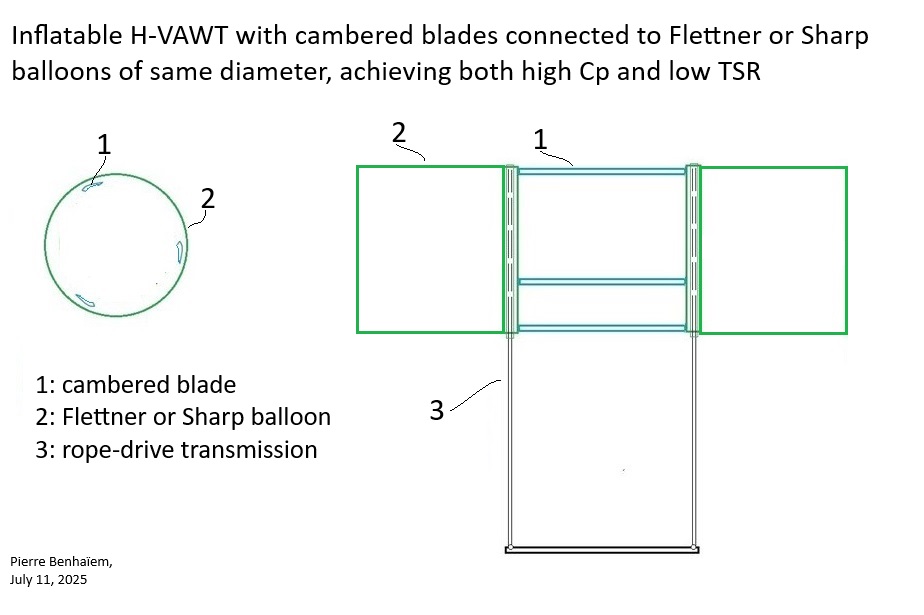
It can be noted that an advantageous aligned layout (same diameter) of the central VAWT and Magnus-effect based balloons cannot be achieved with straight blades due to too high TSR (greater than 1) leading to a too high power consumption or too low aspect ratio of said balloons, as seen in the scenario 2.
A study [29] indicated that high solidity H-VAWT using cambered blades would allow for a high Cp (about 0.3 to 0.5) with a low TSR (below 1).
And for inflatable (Shapewave ® [9 and 10]) blades, the high solidity is not a major drawback since little material is used. Moreover, the low TSR (1 or lesser than 1) allows to diminish the efforts on the blades, leading to better keep their respective shapes [25].
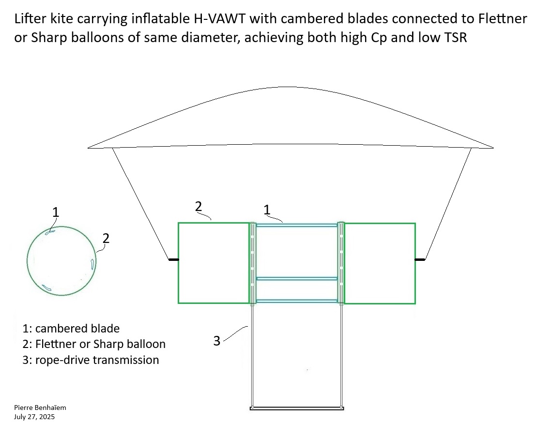
The sketch below takes up certain elements from scenarios 1 and 2, including the assumed diameter of 20 m of the VAWT. However, the TSR is assuming to be 0.8 instead of 1.6, leading to a power consumption eight times lower, allowing each of the Flettner balloons to be extended eight times. The span of each ballon becomes approximately 20 m, and 40 m for both, plus the 20 m span of the central VAWT.
Note that the TSR of a Sharp rotor is also about 0.8 or even 1, which would help avoid energy consumption regardless of the length of the Sharp balloons, which therefore is without limit.
For the reasons stated above, this is by far the most advantageous variant of all the variants described in the preprint.
A kite can suspend the H-VAWT-Magnus or Sharp balloons as outlined below, just like for previously described devices. However, this does not seem advantageous and adds complexity in handling. The buoyancy of the balloons (and perhaps also of the blades) is achieved by inflating with hydrogen or helium, or by hot air using a central heating cable (see above) or by using thermal solar energy. Solar photovoltaic film can be added around the balloons and blades.
A comprehensive analysis of solidity for cambered darrieus VAWTs - ScienceDirect
Also available (full text) on (PDF) A comprehensive analysis of solidity for cambered darrieus VAWTs.
This VAWT-Magnus one-piece AWES would be a Variable speed wind turbine. “Variable-speed wind turbines cannot be directly connected to a transmission system”, but seem to be designed for an individual use, just like Kiwee and some other AWES.
A variable speed wind turbine is one which is specifically designed to operate over a wide range of rotor speeds. It is in direct contrast to fixed speed wind turbine where the rotor speed is approximately constant. The reason to vary the rotor speed is to capture the maximum aerodynamic power in the wind, as the wind speed varies. The aerodynamic efficiency, or coefficient of power, Cp
for a fixed blade pitch angle is obtained by operating the wind turbine at the optimal tip-speed ratio as shown in the following graph.
The case for variable speed wind turbines
Originally, wind turbines were fixed speed. This has the benefit that the rotor speed in the generator is constant, so that the frequency of the AC voltage is fixed. This allows the wind turbine to be directly connected to a transmission system. However, from the figure above, we can see that the power coefficient is a function of the tip-speed ratio. By extension, the efficiency of the wind turbine is a function of the tip-speed ratio.
Ideally, one would like to have a turbine operating at the maximum value of Cp at all wind speeds. This means that as the wind speed changes, the rotor speed must change as well such that Cp = Cp max. A wind turbine with a variable rotor speed is called a variable-speed wind turbine. Whilst this does mean that the wind turbine operates at or close to Cp max for a range of wind speeds, the frequency of the AC voltage generator will not be constant. This can be seen in the equation N = 120 f/P, where N is the rotor’s angular speed, f is the frequency of the AC voltage generated in the stator windings, and P is the number of poles in the generator inside the nacelle. Therefore, direct connection to a transmission system for a variable speed is not permissible. What is required is a power converter which converts the signal generated by the turbine generator into DC and then converts that signal to an AC signal with the grid/transmission system frequency.
The case against variable speed wind turbines
Variable-speed wind turbines cannot be directly connected to a transmission system. One of the drawbacks of this is that the inertia of the transmission system is reduced as more variable-speed wind turbines are put online. This can result in more significant drops in the transmission system’s voltage frequency in the event of the loss of a generating unit. Furthermore, variable-speed wind turbines require power electronics, which increases the complexity of the turbine and introduces new sources of failures. On the other hand, it has been suggested that additional energy capture achieved by comparing a variable-speed wind turbine to a fixed speed wind turbine is approximately 2%.[3]
After some analyses and recent experiences, it turns out that the rope-drive system is not operable unlike, for example, that of the Kitewinder Kiwee One [5]. The patent [31] indicates a problem when the pulley guiding plan (here around the Savonius or Darrieus H-VAWT rotor) is perpendicular to the axis of rotation. This problem is not solved with the addition of the lifter kite. This conclusion is also applicable to similar devices [32 and 34].
It is the reason why a last design is sketched, including ring generators aloft.
(PDF) Vertical axis wind turbine(s) connected to Flettner or Sharp balloons. Available from: https://www.researchgate.net/publication/384229571_Vertical_axis_wind_turbines_connected_to_Flettner_or_Sharp_balloons [accessed Aug 30 2025].
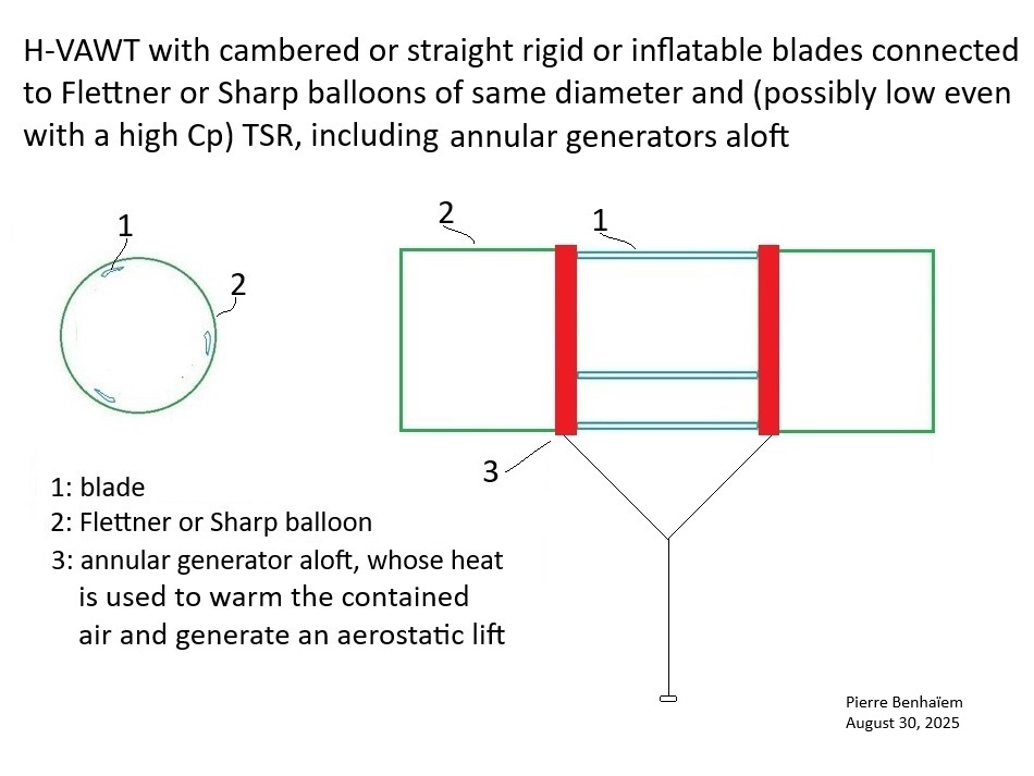
Annular generators aloft for the variant above (Numerical assumptions…), static flight
The difficulty of rope-drive transmission is circumvented by the implementation of ring generators, the stators being the fixed parts hold with the tethers also conveying electricity, while the rotors rotate at the same time as both balloons and H-VAWT. This arrangement looks to be the more promising among the others in this preprint.
Takeoff and landing are facilitated and can be automated. Indeed, the AWES can rest on the ground and land via the shells covering the fixed stators of the respective generators which are used as motors to initiate rotation and takeoff, while the balloons benefit from a slight aerostatic lift from the heat produced by the motor-generators.
(PDF) Vertical axis wind turbine(s) connected to Flettner or Sharp balloons. Available from: https://www.researchgate.net/publication/384229571_Vertical_axis_wind_turbines_connected_to_Flettner_or_Sharp_balloons [accessed Aug 30 2025].
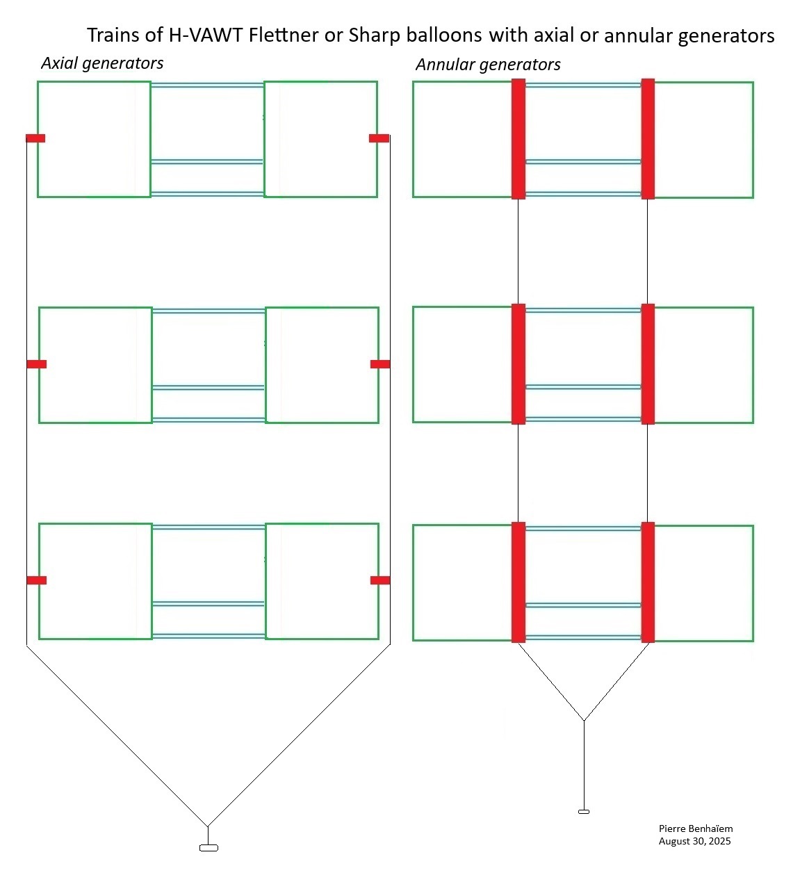
Trains of H-VAWT Flettner or Sharp rotor with axial or annular generators (based on the previous paragraph and on” Numerical assumptions…”), static flight
Takeoff and landing are possible if unities are on the ground, takeoff starting with the unit at the top, landing starting with the unit below.These trains could allow large scaling because the units are static.(PDF) Vertical axis wind turbine(s) connected to Flettner or Sharp balloons. Available from: https://www.researchgate.net/publication/384229571_Vertical_axis_wind_turbines_connected_to_Flettner_or_Sharp_balloons [accessed Aug 30 2025].
A version to power @dougselsam 's house:
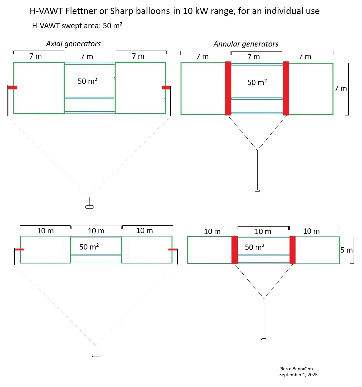
Individual H-VAWT with Flettner or Sharp balloons and generators aloft
Design according to the same model as before (60 m by 20 m, swept area of the H-VAWT: 400 m²), but smaller (21 m by 7 m, or 30 m by 5 m if we expect a better aspect ratio for the Magnus or Sharp balloons), in the 10 kW range and for individual use. Swept area of the H-VAWT: 50 m².(PDF) Vertical axis wind turbine(s) connected to Flettner or Sharp balloons. Available from: https://www.researchgate.net/publication/384229571_Vertical_axis_wind_turbines_connected_to_Flettner_or_Sharp_balloons [accessed Sep 01 2025].
I think it is because the radial traction towards the VAWT-Flettner balloon (or any wheel) prevents rotation. In contrast, the traction towards Kiwee is an axial traction, after transmission to the right angle idler pulley. Similarly the traction towards Keuka wind turbine (or any regular wind turbine) is an axial traction, allowing torque transfer through rope-drive cable surrounding this rim-driven wind turbine, as shown on the video below (from 1:37):

The rope-drive cable could perhaps be replaced with @Freeflying 's annular generator.
1 Like
Funny you mention flettner balloons using an annualar generator. I was thinking the other day of a balloon concept where the annualar generator could be used? By inflating the balloon just enough for the ring of the generator to hold where it would sit on the outside of the balloon and not move. Depending how long the balloon is? You could have multiple annualar generators along its length? A balloon would provide support for the annualar generator. preventing the annualar generator tubing collapsing under the weight of coils. It would be a great use for an annualar generator.
Further more any structure that can provide rigidity for the annualar generator would be a good thing at scale. Where you could nest annualar generators on a hawt superstructure to provide more power? It kind of reminds me of a spiral water wheel pump
https://youtu.be/wCxRHueX6jQ?si=f6BON4GX7M3oHxnU
The same could be done for my annualar generator? Leading to more conductive events. That’s just one of many options for an annualar generator? I hope in time I can demonstrate a few more? as I’m in the market for a kite surfing kite. To lift the annual generator skywards. But a balloon should do the same where it is applied.
There are several sorts of annular generators. The simplest could be generators using wheels for the rim-driven wind turbine, like on
and also on

Keuka used also the rim-driven system, then a variant with a rope-drive cable.
I think other variants of large annular generator with a stator and a rotor rotating around the said stator are difficult to implement.
Finally, we have the gravity annular generator such like the one suggested by @Freeflying.
For a VAWT-Flettner balloon, I suggest annular generators, but I don’t know if they could really work because they could block the rotation (like rope-drive system), although perhaps that wouldn’t be the case due to the ball bearings (for the variant with a stator and a rotor) or wheels (for the rim-driven variant).
1 Like