FlygenKite

A very ordinary inner tube.
Below are the photos of the experiment:

The tire (inner tube) has an internal section which reduces towards the middle, and increases again, just like a fairing for a shrouded wind turbine. During the experiment the wind really increased with a tire.

1 Like

Experiment Findings is a rarely used category that fits the content well. The content has been completed with outdoor experiments. Some excerpts in addition to the sketch and the photos above:

Experiments of the elements with a fan
With a 40 cm diameter fan, I experimented a 23 cm diameter propeller alone, then inside a tire (inner tube) of 42 cm outer diameter and 24 cm inner diameter. And the propeller spun much faster inside the tire than alone. My measuring instruments were the sound produced by the propeller, and the pain of the fingers to stop it, with (ouch!) or without a tire. But as wind speeds were too variable depending on the location in relation to the fan, outdoor experiments with natural wind were necessary.

Experiments of the elements outdoor

The same tire (inner tube) was used, with the same 23 cm diameter propeller then a 20 cm diameter propeller. A buoy of 85 cm outer diameter and 38 cm inner diameter was also experimented, with a 35 cm diameter propeller.

Wind speed was 3-4 m/s. The rotation of both 20 cm and 23 cm diameter propellers was faster within the 42 cm tire than that of the same propellers alone, while the rotation of the 35 cm diameter propeller was significantly faster than that of the same propeller alone.

Likewise, placing my face inside the buoy, I felt a significantly faster wind.

A little later, the wind having decreased (being 2 m/s), measurements were made with an anemometer, also showing an increase in wind speed in the middle of the tire, and a significant increase in the middle of the buoy. The wind speed having been variable, it was difficult to quantify it, and was perhaps of the order of 1.25 times with the buoy.

The elements used outdoor

(PDF) Flexible kite carrying a turbine within a torus-shaped balloon. Available from: https://www.researchgate.net/publication/388800040_Flexible_kite_carrying_a_turbine_within_a_torus-shaped_balloon [accessed Feb 10 2025].

Page 5:

With an entire volume of 220 mÂł, the balloon has a lifting force of 130 kg (without cable loop)

So the weight of the torus could be about 90 kg, so far less than the weight of a corresponding wind turbine inside.

More accurate measures and data could help to see if shrouded-shaped balloons would be far better by taking account of the weight.

About shrouded wind turbines:

The shrouded wind turbine with a brimmed diffuser has demonstrated power augmentation by a factor of about 2–5 compared with a bare wind turbine, for a given turbine diameter and wind speed.

Also:

DWT’s wind turbine produces 50% more energy than a conventional turbine with the same rotor size.

@dougselsam will perhaps tell: why adding weight due to the shroud while a larger rotor will be less expensive?

Sure, the weight of a shroud is significant. But inflatable cheap and light shrouds (like the experimented tire) could perhaps be used for some AWE configurations I mention in these experiment findings.

Nicely done getting test data @PierreB
I’m going to stay sceptical that an inflated shrould is worth flying as a kite.
What I remember of Altaeros was that they had a problem with blowdown.
Basically more drag as the wind picked up ruined their altitude.
If the shroud however could be oriented to be lift generating and the turbine mounted inside this effective kite shroud and still have flow enhanced
 sure why not.
Someone give Pierre a bunch of smiling students and a €300 billion grant

You are right to be skeptical. The torus or any other shroud has the effect of concentrating the wind on the turbine. You shouldn’t expect anything else from a vertical torus, especially not that it flies like a kite.

In the complete sketches I therefore added the kite: in all it is a variation of the FlygenKite. This would make it possible to rely less on helium.

That said, we can imagine a tethered torus inflated with helium carrying a turbine inside if the drag of the turbine and that of the torus (therefore the force of the wind) remains limited.

But lift generating and power turbine generating through the shroud can be incompatible. Indeed the required angle of attack to generate lift could mitigate the wind area on the shrouded turbine if it is tilted. So I think the only lift is that of aerostatic lift with helium. Or so is a point to check.

This seems likely. Concerning Altaeros and other shrouded BAT, we do not have all the data (in particular the wind speed, the effectiveness or ineffectiveness of the shroud, the angle of attack
).

Concerning the torus-shaped balloon (tire) as a shroud, by my approximate experiments, if the turbine power is 2x, the total drag is about 3-6x: for some AWE applications (crosswind flight), it would be too much; for a static flight under a kite, it would perhaps be a possibility, the torus being light compared to the turbine when scaling.

Right. Do not confuse Torus-shaped balloon with Circoflex kite like the one below. Their respective shapes are quite different.

Beware of disinformation via unsolicited and abusive emails from who-we-know.

1 Like

Oh I can imagine we’ve caused great offence @PierreB
Did the detractor in chief insist circoflex is a torus?
I missed the day in Primary 4 when the teacher said what a kite shape was (She didn’t like maths much) But even I know that circoflex is not a torus.
Not that I was insisting on a vertical torus either but hey ho

Let’s assume a kite (whatever shape) has higher pressure on the underneaty down side
and it has lower pressure somehow on the uppy top side
Hmmm OK and a spinny turbine rotor mounted in a hole similarly planar with the kite surface does the same.

Yeah if you can fly the thing
And if you’re getting more flow through the holey turbine bit - You’re the dude. Go Pierre.

1 Like

He wrote: “Circoflex Torus Kites”. :laughing:

It’s like saying for example: “Spherical Cubic Balloons”. :laughing:

What a newb
Go ask him to get a can of tartan paint from the shed for the new ground station

Hi Pierre: I always find ways to concentrate more wind into a rotor compelling. However, none has ever worked out, despite a lot of money and effort being applied. One reason is any structure needs to be strong enough to withstand 100 mph winds, even solar panels. That makes ducts and shrouds expensive and heavy, whereas adding blade length turns out to be easier.
Other factors are the need to use higher solidity rotors, to control noise and keep tip speeds reasonable, which is less efficient, somewhat offsetting the advantages of the shroud. I’d say the research that claimed 2-5 times the power from a ducted rotor are overly-optimistic, especially at the upper end! They are taking “data” in their own way, torque and RPM, possibly not translating properly to electrical output. Also, I used to think science people, kite people, etc. would always be naturally honest, but scientific fraud and exaggeration are common. Seems pretty common for researchers to try and make their results look even better than they really are. I would not “throw the baby out with the bathwater” on the concept of concentrating the wind thru a rotor. it is definitely a known effect that really does work. But we have to remember, there are a million ways to make SOME power at SOME price and SOME level of reliability from the wind, but not all are practical solutions or improvements. Nonetheless, it is a real effect and may have a place of someone can figure out how to make it worthwwhile. :slight_smile:

1 Like

Hi Pierre: The “brimmed diffuser” is something new to me. It seems to be an application of the old concept of a “Gurney Flap”, pioneered by Dan Gurney for use on Formula-1 Race cars, to a wind turbine shroud.

The Gurney Flap Turns 50 - SPEED SPORT

In the publication you refer, the authors Yuji Ohya and Takashi Karasudani mention two versions in the Introduction:

Furthermore, we placed a wind turbine inside the diffuser shroud equipped with a brim and evaluated the power output generated. As a result, the shrouded wind turbine equipped with a brimmed diffuser demonstrated power augmentation for a given turbine diameter and wind speed by a factor of about 4–5 compared to a standard micro wind turbine.

Furthermore, for the practical application to a small- and mid-size wind turbine, we have been developing a compact-type brimmed diffuser. The combination of a diffuser shroud and a brim is largely modified from the one with a long diffuser with a large brim. The compact “wind-lens turbines” showed power augmentation of 2–3 times as compared to a bare wind turbine.

Basically, the longer the shroud is and has a larger diameter compared to the turbine, the more power increases. But also the more the mass and the drag increase.

Perhaps for FlygenKite (a flygen flexible kite) a compromise could be found to increase the power of the secondary turbines by keeping the same diameter of the turbine, leading to a lighter generator thanks to a higher rpm, without an excess of drag (which would be equivalent to the drag of a larger turbine but not more).

Now my experiments of torus with buoy and tire (inner tube) showed a greater increase in speed with the fat buoy than with the relatively thin tire, and also as a function of the area swept by the propeller in relation to the surface of the torus. A fat torus leads to a relatively longer shroud.

In the other hand there is an excess of drag with a torus because its exterior half part is not a part of the shroud. It is the reason why I think that the torus configuration could be more suitable for static devices, inflated with helium or carried with a static kite, if really it can be applied.

An example of a large torus on the next comment below.

A torus for an inflatable shrouded flying turbine, inflated with helium, and/or under a static lifter kite?

In first, experiments were realized by keeping the tire facing the wind.
I added experiments with tilted tire (so tilted 20 cm propeller) at low then high angle of attack, auto-gyroplane type. Whatever the angle of attack, the propeller inside the tire turned much faster.

Perhaps a path to follow for flygen or torque-based, or yo-yo mode tilted rotors.

1 Like

Hello Pierre: It’s easy to “say” a brim can produce five (5) times the power from the same turbine, but I remain in doubt of that figure. Nonetheless, it is interesting that a sharp corner can accelerate the wind, a fact I’ve been mentioning with regard to a 90 degree corner of a high building on my property where the wind is always way stronger than anywhere else, seemingly as strong as up on the 120-foot-tall tower supporting our 10 kW, 21-foot diameter wind turbine.

Meanwhile, what do you think of my noting that the “brim” amounts to adding a “Gurney flap” to a shroud?

And by the way, the swirl shown as the key enabling feature in the brim promotion looks, to me, to be rotating in the wrong direction to support its alleged effect. I’d say the swirl should rotate outwards from inside the brim, as the wake encounters the sharp corner of where the brim begins, to create a vacuum at that point, pulling more air through the turbine. :slight_smile:

Hi Doug,
A publication shows, in figure 6, a significant decrease of the power coefficient of a shrouded wind turbine, when wind speed increses, here from 2 m/s to 6 m/s:

https://www.researchgate.net/publication/350169818_Shrouded_wind_turbine_for_low_wind_speed

With my torus I also observed a decrease of efficiency when wind speed increased.

That said this decreasing is not observed for the specific shroud you refer (see figure 6):

I saw the similarity (after you mentioned it), but I do not know the aerodynamic causes.

1 Like

Well everyone was surprised at how well the Gurney flaps worked, I think it was a rare case of an aerodynamics layman accidentally making a big discovery that “properly-trained” aerodynamicists would never have tried - a sharp corner. Let’s realize, the “Gurney” flap is just a subset of a regular flap as used on airplane wings to increase lift while lowering airspeed when planes are landing. But regular flaps seldom if ever reach a 90-degree angle from the wing as a whole. I think the magic of the gurney flap is to create a vacuum at the trailing edge that forces the airstream to remain fully “attached” to the suction side of the airfoil. Plus, it probably raises pressure on the pressure side. I’ve watched a lot of wind tunnel videos over the years of flaps, and always wondered about the sharp angle they were placed at, thinking a more curved transition would be more “elegant”. Once again, we have to go with what actually works, as opposed to what “seems” like it “should” work.

Regarding the lower effectiveness of a funnel or diffuser at higher windspeeds,

  1. I’ve never heard about that before;
  2. Sounds like your experiments were limited to low- and very low- windspeeds

I still suspect that the 5x power increase from a brimmed diffuser sounds “too good to be true”, but hey, that’s just what I happen to “think” - subject to modification upon proof or witnessing it myself. :slight_smile:

1 Like

I reproduce a quote from the mentioned publication on a comment, page 7, about Figure 6.

But the efficiency decreases when the wind speed increase for both types of wind turbines, where the shrouded wind turbine has a significant reduction. This is caused by the frequencies of data at measured and collected data, where on the collected data process, frequencies of wind speed 1 - 3 m s-1 is relatively many than frequencies of wind speed above 3 m s-1 which caused the result of average generating power at wind speed 4 - 6 m s-1 . Another thing that affects the generated power on the experiment is the yawing mechanism on the shrouded wind turbine which is not optimal due to the addition of structural loads.

I put again this quote, which seems to ask questions:

This is caused by the frequencies of data at measured and collected data, where on the collected data process, frequencies of wind speed 1 - 3 m s-1 is relatively many than frequencies of wind speed above 3 m s-1 which caused the result of average generating power at wind speed 4 - 6 m s-1 .

What is your advice about it?
On other publications about shrouded wind turbines, I did not see a similar thought nor a drop in efficiency when wind speed increases. An example:

Experimental Investigation of Wind Turbine Using Nozzle-Lens at Low Wind Speed Condition
Authors: Nugroho Agung Pambudi, Danur Lambang Pristiandaru, Basori, Danar Susilo Wijayanto, Husin Bugis, Bambang Dwi Wahyudi, Cyrillus Sudibyo, Karno M.W., Ngatou Rahman, Nyenyep Sriwardani, Subagsono.

Energy Procedia

Volume 105, May 2017, Pages 1063-1069
https://www.sciencedirect.com/science/article/pii/S1876610217305003?via%3Dihub

See Figure 4 and, on pages 1066-1067 (with low values of wind speed), this excerpt:

We can observe that nozzle lens A has increased the wind speed from 2.5 m/s to 3.03 m/s; it increases from 3.5 m/s to 4.5 m/s and from 4.5 m/s to 5.46 m/s respectively. These results are influenced by other RPM and TSR experiment on different lenses.

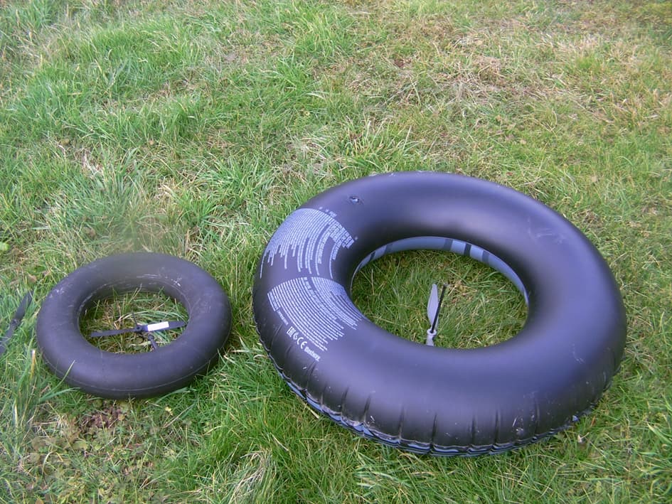
Today I experimented again the wind speed inside the 42 cm diameter tire, then the tire off, using a blower. Wind speed measured with an anemometer was about 8-10 m/s at 1 m from the blower, with or without tire. I did not see any difference. But more accurate measures would be useful, because even low speed variations lead to high difference of power. I will experiment outside on a windy day.

Hello Pierre: As usual, you are good at digging up relevant info. This paper seems to agree with my assessment of how Gurney flaps affect both the suction and pressure sides of the airfoil. Its discussion of so many relevant factors regarding blade erosion and resulting deterioration of blade efficiency over time also point to the naive nature of the decade+ of “opinions” expressed by hopeless perpetual-newbie know-nothing(s?) in discussions about hard blades, versus soft fabric attempts with their limited performance and lifespans. :slight_smile:

I think there was an interference caused by my arm holding the anemometer inside the tire and which limited the wind speed, said interference maybe increasing with wind speed.

In order to improve the accuracy of measures, avoiding some interference which could have distorted the previous measurements, an anemometer was settled inside the tire. Another anemometer (with apparently the same measurement calibrations) was used simultaneously in order to see the difference of the wind speed in free air and the wind speed inside the tire.

I just made again this experiments, using a bower on a chair. At 1 m of the blower the air speed was about 6.5 m/s, and 7.8 m/s (20 percent higher) for the anemometer inside the tire exactly at the same place than the other anemometer (6.5 m/s).

A similar increase of about 20 percent was observed outdoor with wind speed of 2-3 m/s, by using the same tire with the same anemometer inside, and the same other anemometer.

A little later the wind increased to an average of 4 m/s, peaking at 5.8 m/s. The anemometer inside the tire showed an increase in wind speed of around 20 percent, peaking at 7 m/s, and with an average of 4.8 m/s. In the same time when the tire with the anemometer was tilted, the wind speed dropped drastically (from about 5 m/s to 3 m/s), even at an angle of attack higher than 45 degrees. In vertical position, the tire achieves unambiguous efficiency.

Measurements with high wind speeds remain to be taken, but it can be stated that the tire’s effectiveness does not depend on wind speed.