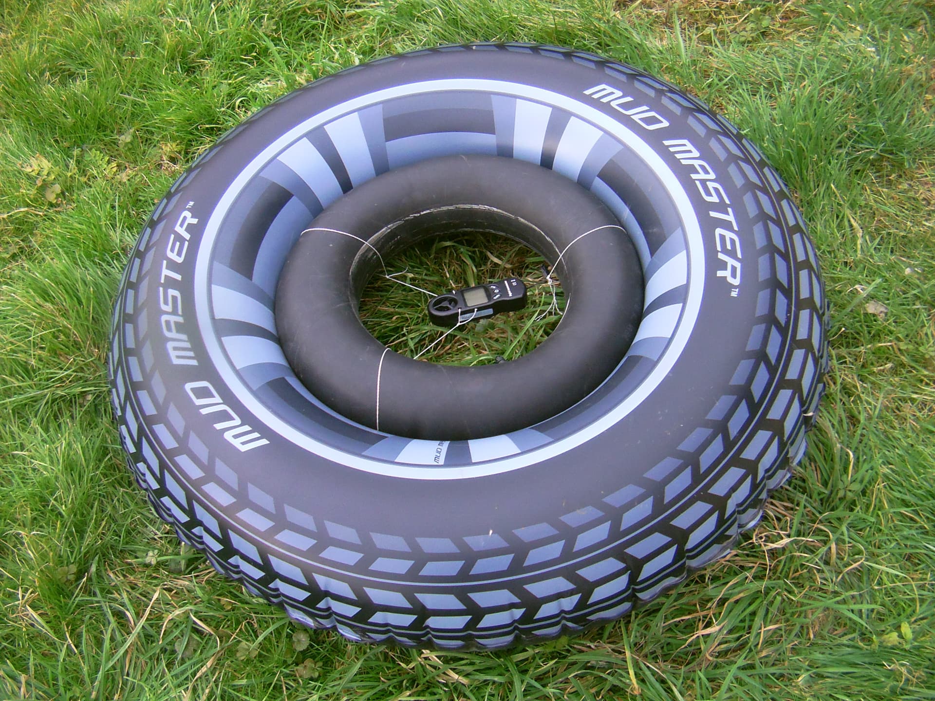
And now, with the 42 cm tire within the 85 cm buoy, will the increase be even greater?
A windier day. Anemometer alone, average 6 m/s, peaking at 7.3 m/s, anemometer within 42 cm tire, average 7.2 m/s, peaking at 8.8 m/s (always 20% faster, at several wind speeds).
Then the whole in the buoy was not better, peaking at 8.3 m/s.
That said tests were performed again because (compared to the anemometer in the same 42 cm tire but with not taut enough wires):
Previous measurements were underestimated due to lack of tension in the wires holding the anemometer. This is the reason why other tests were carried out with a higher tension of all the wires holding the anemometer which was able to position itself facing the wind in all circumstances. The measured increase of efficiency was significant, being approximately 25 percent. Measurements in a windy day gave the following values at three different wind speeds: an anemometer alone and another anemometer in the 42 cm tire (as previously) in the same time: respectively 6 m/s and 7.5 m/s; 7.4 m/s and 10 m/s (unusual increase); 10.2 and 12.6 m/s. In all tests, the proportion of increase does not appear to depend on wind speed.
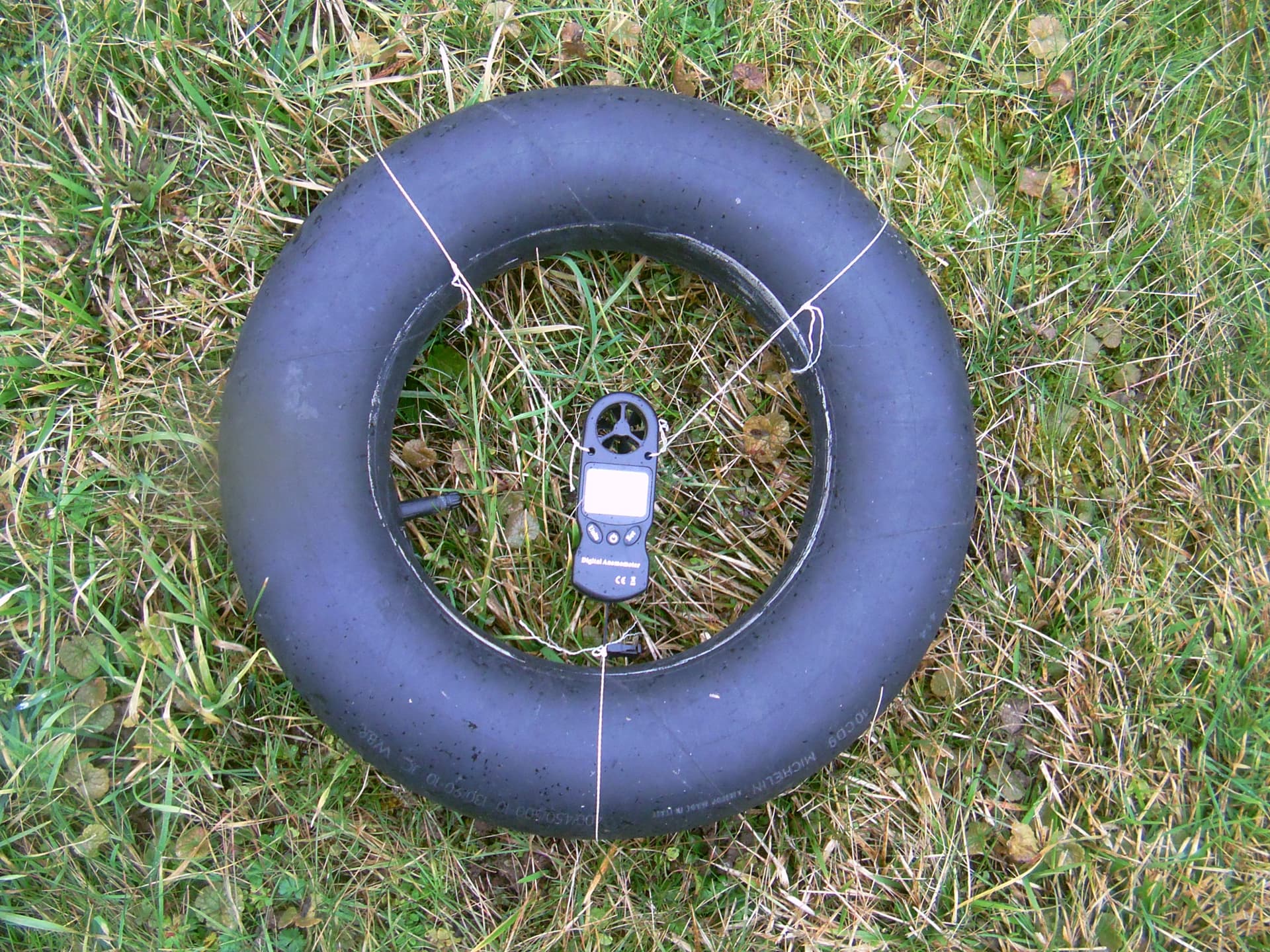
Anemometer in the tire well positioned with taut wires
A more compact option was added in these experiments.
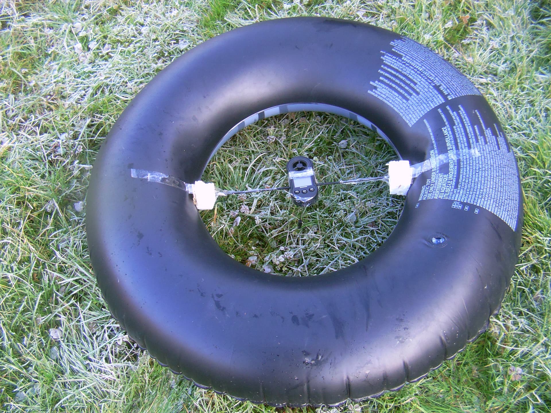
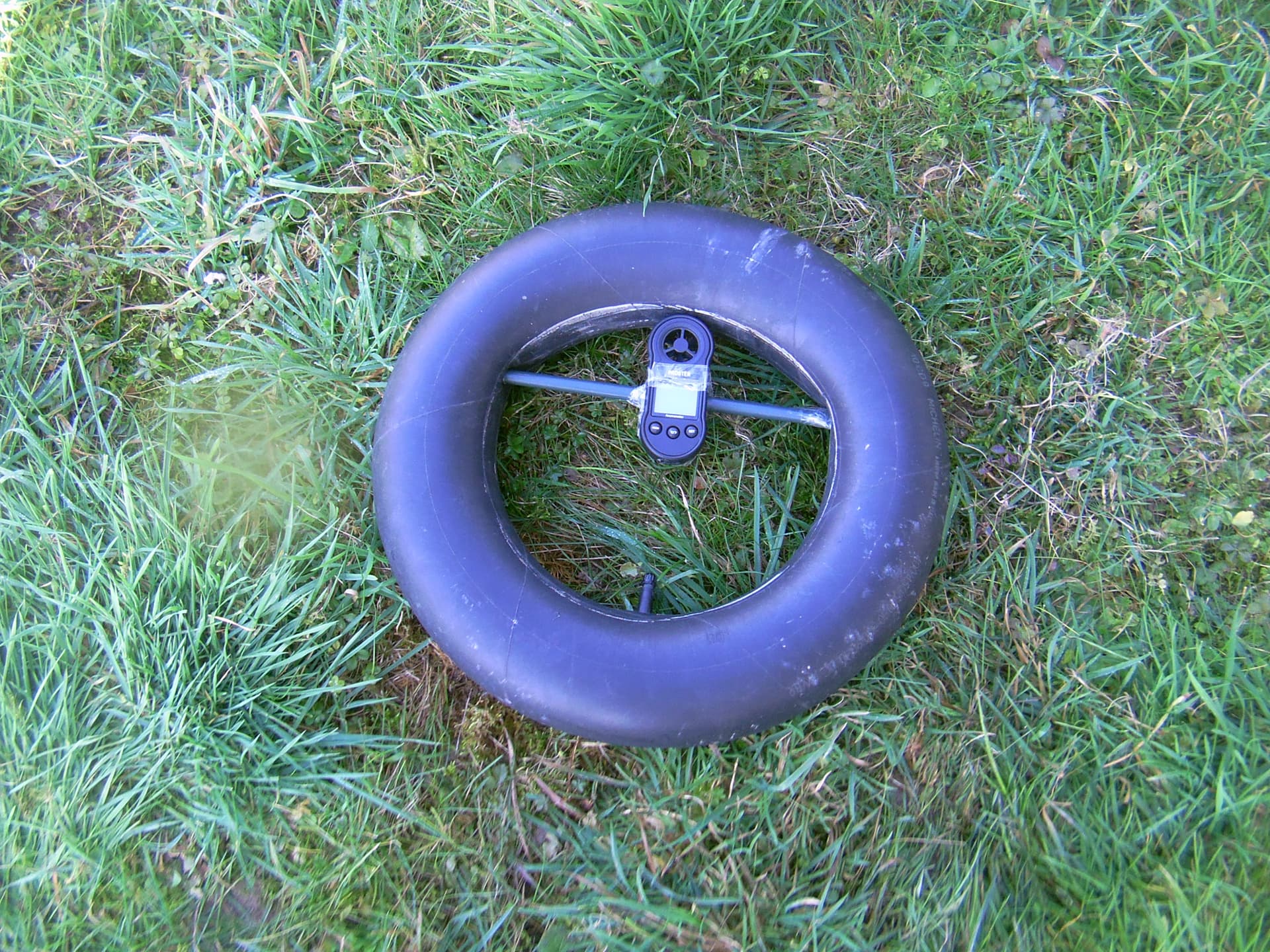
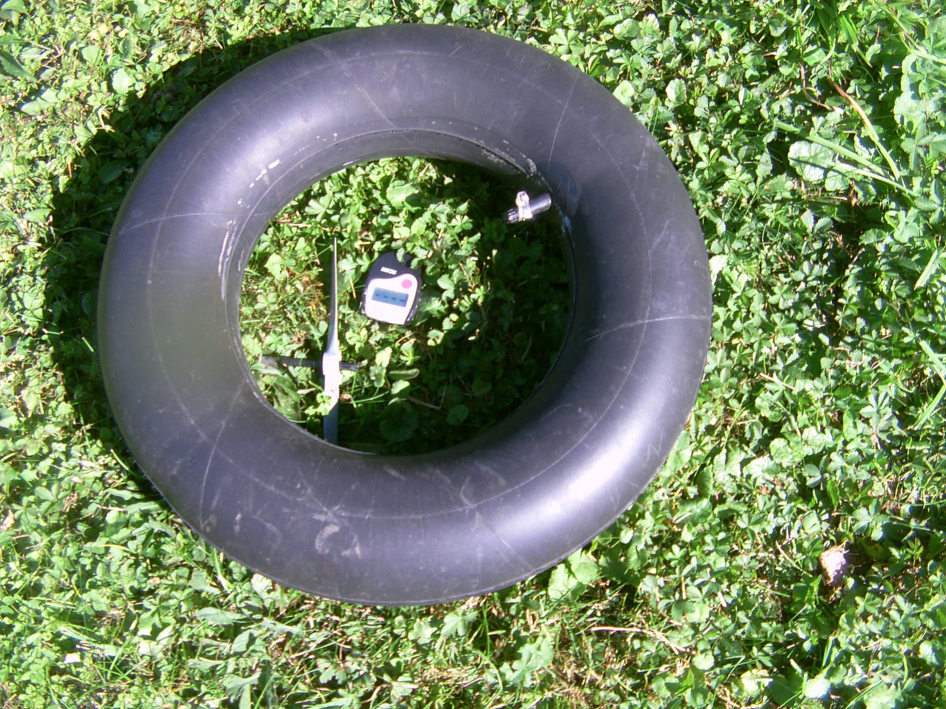
Experiment with an anemometer inside the 85 cm diameter buoy (photo below). This was far less efficient than with the 42 cm diameter tire (see above). Wind speed inside the buoy was slightly higher than that in free air, approximately 5 to 10 percent more, instead of 25 percent increase with the tire. Perhaps the relatively greater thickness of the buoy further slows down the entry of air.
Today other measures were performed with the efficient 42 cm diameter tire.
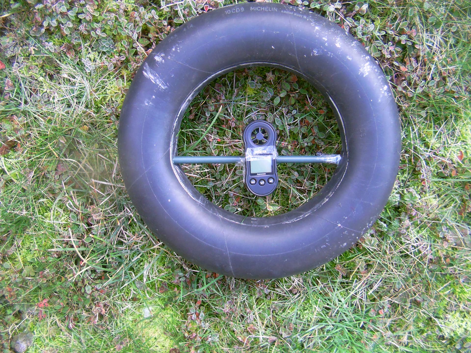
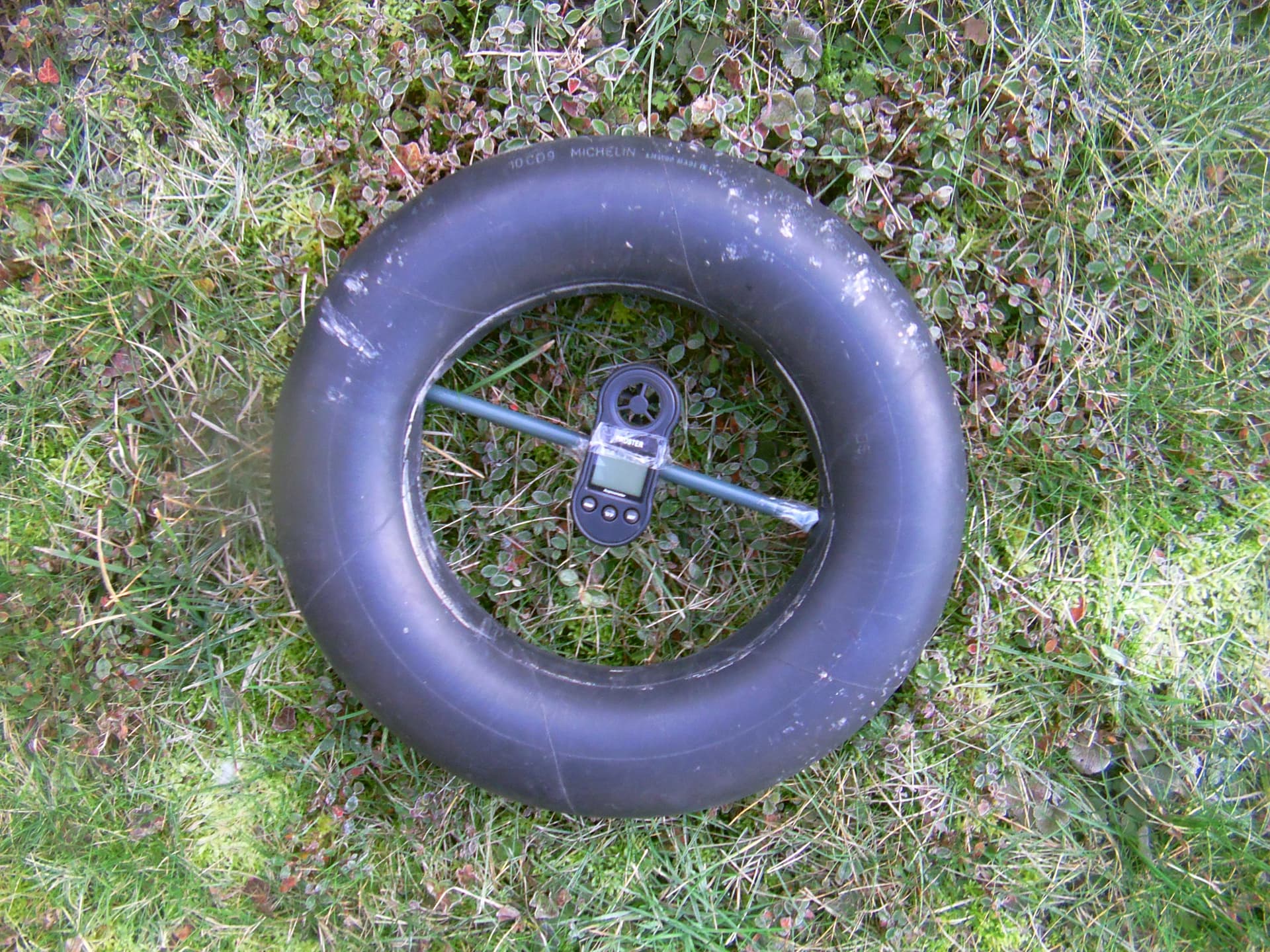
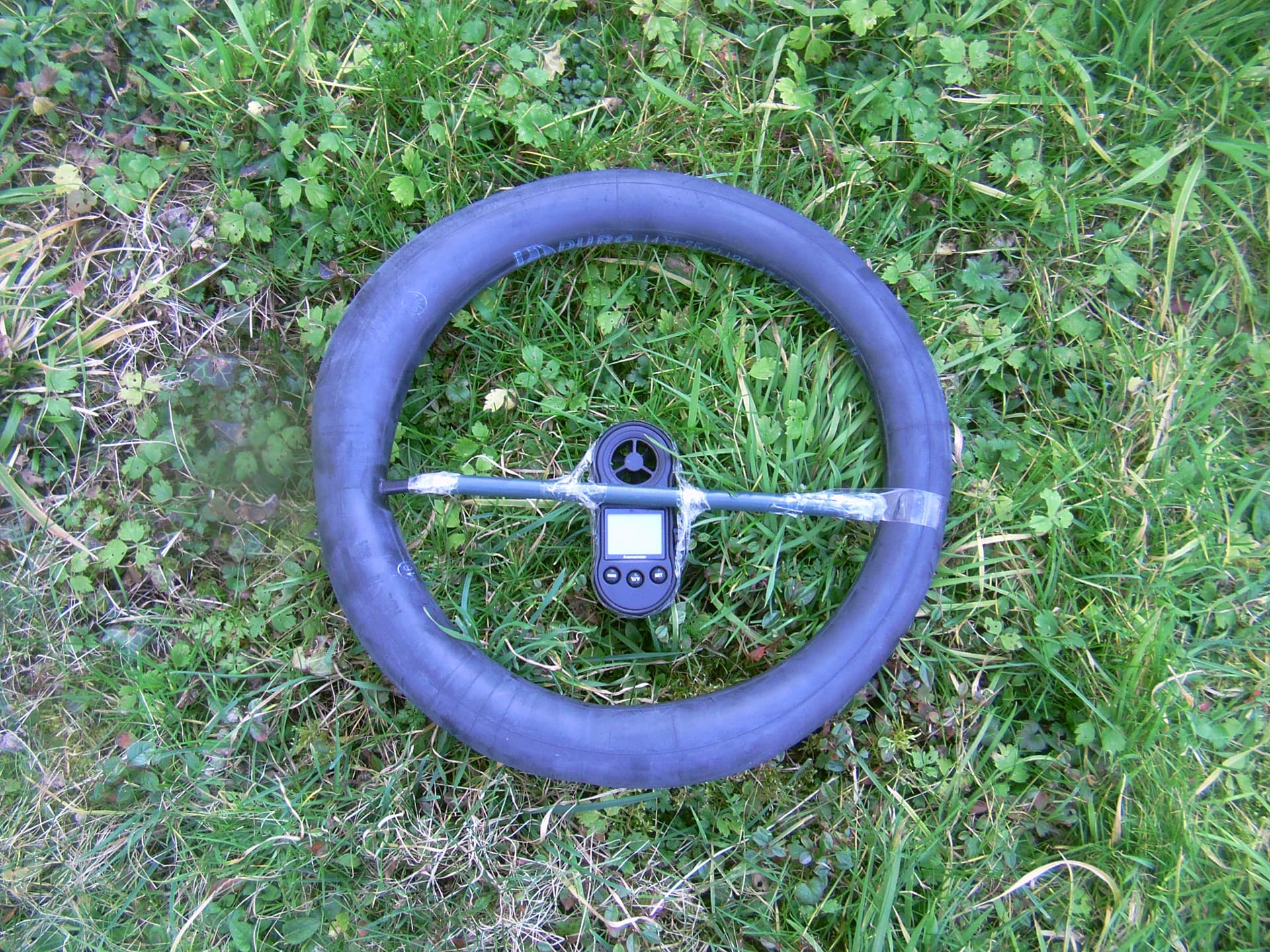
Then other measures were performed by reversing the two anemometers, the one inside the tire on a tube, and the other one in free air. Said tube was moved through three positions, so that the anemometer rotor was placed in the center, then between the center and the edge, then at the edge, as shown in the next three photos. Wind speed in free air was 4 to 5 m/s. As previously, the anemometer inside the tire indicated a value 25 percent higher, so respectively 5 m/s for 4 m/s in free air, and 6.25 m/s for 5 m/s in free air,regardless of its position at the center or at the edge or between the two.The effectiveness of the 42 cm diameter tire as a shroud was therefore confirmed in the different experimental configurations.
(PDF) Flexible kite carrying a turbine within a torus-shaped balloon. Available from: https://www.researchgate.net/publication/388800040_Flexible_kite_carrying_a_turbine_within_a_torus-shaped_balloon [accessed Mar 02 2025].
Anemometer rotor in the center of the 42 cm tire
Anemometer rotor between the center and the edge of the 42 cm tire
Anemometer rotor on the edge of the 42 cm tire
1 Like
Almost the size, and also almost the weight which is only 640 kg.
With my experiences on tires and torus, I was seeing if we could do something simpler by carrying a turbine shrouded by the torus and suspended with a kite or a Flettner balloon.
As wind turbines quickly become too heavy, we should limit ourselves to small wind turbines of 5 or 10 kW maximum, perhaps of type rope-drive Kiwee @Kitewinder , for individual use, in bumper car mode allowing collisions without consequences between neighbors’ AWES.
If, as the tests have shown, the 42 cm diameter tire makes it possible to increase the wind speed by a quarter, this would almost double the power if we do not take into account the negative parameters: the power would have to be measured with a turbine and not just the increase in wind speed.
Cons: the torus shape adds a lot of drag, especially because the outer half torus area adds a large area leading to useless drag.
I evaluated the total drag with the torus, as between 1.5 and 2 times the drag of a non-shrouded wind turbine sweeping a doubled area.
Indeed, if the power is almost doubled, the same goes for the drag or thrust for the turbine (“normal” thrust coefficient Cd of 0.9 before being doubled when the turbine is augmented). We must add the drag by the torus itself, and whose coefficient Cd would be 0.8, as shown on Figure 4:
So a drag calculation was sketched. I am not sure if it is correct.
0.42 m diameter tire; diameter throat = 0.24 m. Length Lt = 0.09 m (= thickness of the tire). Lt/D throat = 0.375. D useful shroud = 0.33 m. Lt/D shroud = 0.272. Full torus area = 0.093274 m²; outer half torus area = 0.053 m²; inner half torus area = 0.08548 m² - 0.0452 m² = 0.04 m²; diameter 0.33 m disc including inner half torus area = 0.08548 m²; inside 0.24 m diameter D throat area = 0.0452 m²; 0.08548/0.0452 = 1.89, so 1.9; complete area of 0.42 m diameter disc = 0.138474 m², so about 3 times diameter throat area; outer half torus (useless drag) area = 0.053 m² with 0.8 Cd with 90° angle of attack 0.42 m diameter tire; diameter throat = 0.24 m. Length Lt = 0.09 m (= thickness of the tire). Lt/D throat = 0.375. D useful shroud = 0.33 m. Lt/D shroud = 0.272. Full torus area = 0.093274 m²; outer half torus area = 0.053 m²; inner half torus area = 0.08548 m² - 0.0452 m² = 0.04 m²; diameter 0.33 m disc including inner half torus area = 0.08548 m²; inside 0.24 m diameter D throat area = 0.0452 m²; 0.08548/0.0452 = 1.89, so 1.9; complete area of 0.42 m diameter disc = 0.138474 m², so about 3 times diameter throat area; outer half torus (useless drag) area = 0.053 m² with 0.8 Cd with 90° angle of attack according to the Figure 4, so slightly higher than diameter throat area, and slightly lower (0.0424) by taking account of the 0.8 Cd. Power is 1.9 times the turbine area, while drag (thrust) is 0.9 Cd x 1.9 x 00.45 = 0.07695 for the turbine, plus 0.8 Cd x 0.093274 m² (full torus area) = 0.0746192, so 0.1515692. A turbine sweeping 1.9 times more would have a drag of 0.07695, so almost 2 times less for the same power. But perhaps it is not correct to count both augmented drag of the turbine and drag of the inner half torus area (0.04 m² x 0.8 = 0.032), which leads to 0.1195692, so only 1.5538 times more drag. The useless part of drag of the outer torus area represents 0.053 m² x 0.8 Cd = 0.0424.
Another experiments with a thinner inner tube.
Anemometer in the 36 cm diameter inner tube
Anemometer inside the 36 cm diameter inner tube
It was used an inner tube with a thinner but irregular section of 4.5 cm on average instead of 9 cm for the 42 cm diameter tire. The tests with two anemometers including one in the free air showed higher values inside the said inner tube. These values were slightly higher than that of the 85 cm buoy, but lesser than that of the 42 cm tire. These values were slightly higher than those of the 85 cm buoy, but lower than those of the 42 cm tire, and tended to come closer together as the wind speed increased, unlike the 42 cm tire: thus for a wind speed of 3 m/s, we had 3.7 m/s in the 36 cm inner tube, and for a wind speed of 4.5 m/s, we had 5.3 m/s, while a wind peak of 6.5 m/s corresponded to a peak of 7 m/s in the 36 cm inner tube.
Hi Pierre: You are very thorough in your research. I am surprised you get so much enhancement in speed from such a narrow inner-tube profile compared to its diameter! All very interesting. ![]()
Hi Doug, at low wind speed (3 m/s vs 3.7 m/s), but not above (6.5 m/s vs only 7 m/s). The 42 cm tire is better, but the fatter buoy is worse.
Hydrogen balloon transportation: A cheap and efficient mode to transport hydrogen - ScienceDirect
A quote of this publication, then a comment, then a sketch were added to the Experiment Findings.
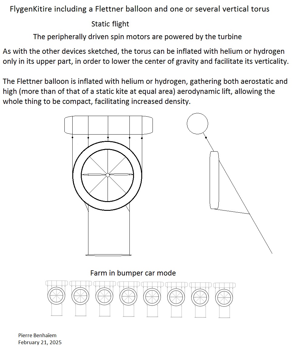
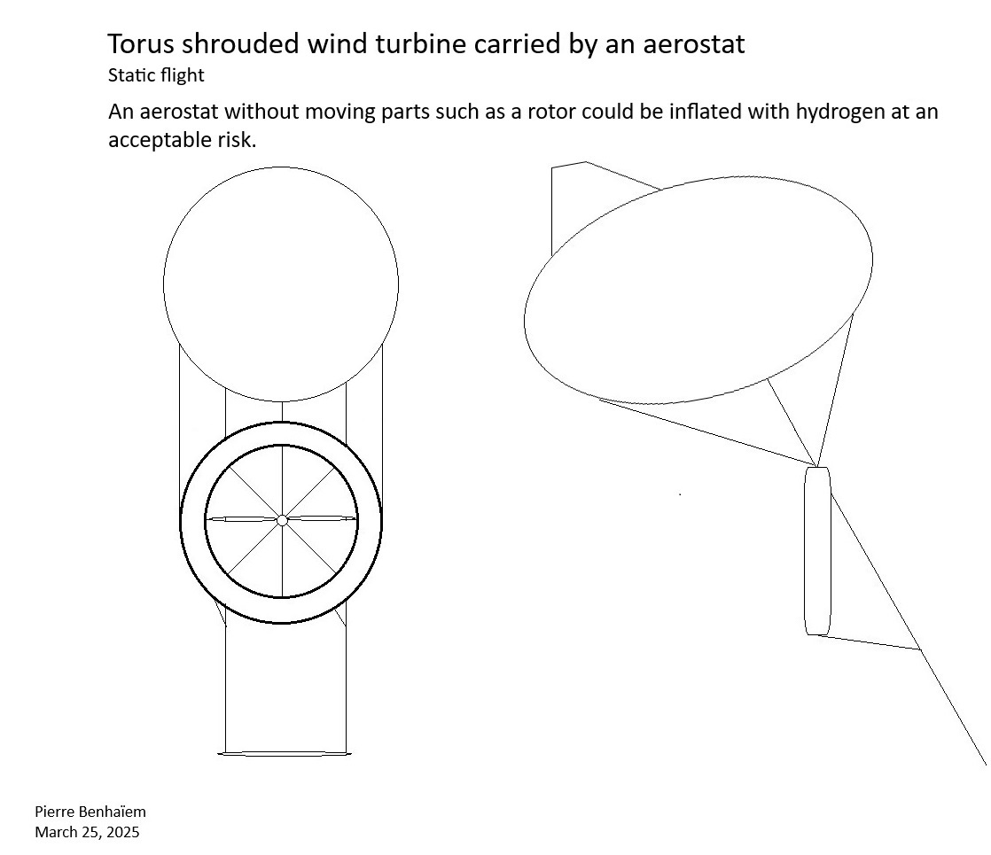
Torus shrouded wind turbine carried by an aerostat
“2. Hydrogen balloon transportation (HBT) […] To reduce the risk of explosion, hydrogen balloons should not have propellers or other moving parts.” [13]It is the reason why a static aerostat without moving parts causing frictions could be preferred to allow the use of hydrogen which is cheaper and more widespread than helium. The aerostat can include an aerodynamic lift."
Hi Pierre: Nice sketch. Yes we’ve always acknowledged hydrogen as a lifting gas, potentially useful for AWE. ![]()
But later tests showed that once again the anemometer in its 36 cm inner tube was not well
fixed and leaned downwind, more so as wind speed was higher. This is why the fasteners (by
adhesives) were consolidated: as a result the anemometer in the inner tube indicated
higher values, even with higher winds: 7.9 m/s then a peak of 8.6 m/s for the free
anemometer, for respectively 8.5 m/s and 9.2 m/s for the anemometer in the inner tube.
Although the measurements were made carefully, the results remain too uncertain due to
the very rapid variations in wind speed which increase the already large margin of error for
relatively small increases in wind speed inside the 36 cm and then 42 cm diameter inner
tubes.
Thus, the recent additional tests in winds of 4 to 10 m/s have shown no perceptible increase
inside the inner tube, whether it was 36 cm or 42 cm in diameter. The same anemometer
was used alone and then inside the 42 cm inner tube, and in a setup that allowed you to
switch from one position to another very quickly and without excessive interference.
Too bad you can’t perform these tests in a wind tunnel. You would have your answers in minutes.
1 Like
Not sure. The high value of 12.6 m/s inside the 42 cm inner tube was achieved with the anemometer providing values that are too high compared to the other. Then this anemometer began to seize up and emit a more and more frictional noise, so that the two anemometers gave more or less equal values for a while and from a certain wind speed, and finally the anemometer that gave these high values ended up giving lower values than the other anemometer that I used, alone, for the latest experiments.
Moreover, the speed of the propeller inside the 42 cm inner tube was perhaps only an impression because of the noise produced, and also perhaps because of a greater stability of the flow which was enough to accelerate the propeller then turning empty.
Certainly, but I make do with what I have.
Wind tunnel results are notoriously meaningless for small wind energy devices, usually used by the next “Professor Crackpot” to artificially force air through an otherwise inefficient vertical-axis turbine that takes up too much area of the tunnel for the results to be meaningful.
You’re better off using a well-designed and well-constructed truck-testing rig, placing the turbine in an open flow, more representative of actual wind than what a wind tunnel can provide. That also allows you to see how your toy fares at highway speeds, which it would see in normal operation at some point. it’s usually above 30 mph you will see your generator being challenged, and over 40 mph when you may be exposed to a catastrophic failure, forcing you to abandon or modify your design. Or the failure might modify your design for you. Not that I would have any way to know this… ![]()
My experiments were not easy because of one of the two anemometers. However, I eventually saw that the inner tube did not lead to an increase in wind speed.
Some update, showing the inefficiency of anemometers (because of too variations), better measures being done by using a rpm-check, indicating a potential of double the power, which confirms some previous approximate evaluations with anemometers.
The rotors of anemometers are small and light, leading to a low inertia, hence too fast variations compared to those of a propeller with a diameter of 20 cm (sometimes 23 cm) which was also used.
While anemometers were finally not useful, the impression of a greater speed of the propeller inside the 42 cm tire (inner tube), the most efficient according to first rough evaluations, was confirmed with measurements using an rpm-check.
Measures with a rpm-check
With the same fan, a rpm-check was used.
Measured rpm (135 x 10) 1350 (sometimes 1400 even more inside) with the 42 cm tire, and rpm oscillating between 1050 and 1100, more often 1050 without tire. The wind speed is directly derived from the rpm.135/105 = 1.2857. So, wind speed is 1.2857 times higher with the tire. 105² = 11025, and135² = 18225. 135²/105² is about 1.65 times. 105³ = 1157625, and 135³ = 2460375.135³/105³ = 2.125, which is more than double the power. And the experiments with the rpm-check all yielded the same result in front of this fan. The difference in speed was obvious, the acceleration much stronger with the tire, and the pain and difficulty of stopping the propeller with fingers was greater. The same was going for outside.
(PDF) Flexible kite carrying a turbine within a torus-shaped balloon. Available from: https://www.researchgate.net/publication/388800040_Flexible_kite_carrying_a_turbine_within_a_torus-shaped_balloon [accessed Sep 10 2025].
42 cm tire (inner tube), propeller, and rpm-check
Hello Pierre: The inner side of a tire tube, surrounding the central hole, has the shape of a typical concentrator or funnel on the windward side, and the typical shape of a diffuser, which tends to create a vacuum, on the downwind side. The combination of the concentrator and diffuser would be expected to increase the wind speed through it. This is not new information, the fact that a tire inner tube can naturally achieve this shape, while being inflatable, easily obtaind, and potentially buoyant, is notable for experimantal purposes at least, although for larger systems, it might be difficult to find tire tubes big enough. What I’ve wondered about with the longer Altaeros-type tunnels is how much the tunnel length impedes airflow, weighing against the concentrator/diffuser effect.
Hi Doug,
A 22 m diameter tire tube:

A 16 m diameter wind turbine would get about 50 kW with 10 m/s wind speed, perhaps doubled with the tire. The scale is largely sufficient for individual use such as powering your home, and for industrial use by stacking the units side by side with little risk (?), and lifted by kites or aerostat lifters.
The length of the assembly should help to increase its efficiency, provided that the constriction remains reasonable, which does not seem to be the case for S500 or S1000.
In addition, the angle of attack required for aerodynamic lift also partially closes the opening, leading to less wind in the turbine.
I agree with this good point. Good example of a larger torus, Pierre. It still seems too thin to concentrate much wind. Also, with all these buoyant structures, even blimps, the armchair designers have often not experienced the magnitude of forces and weight involved with wind turbines. A good example is the original Altaeros structure, touting its MIT origins as evidence of credibility: A person like me, with some experience in wind energy, was able to categorically announce it was not in fact powering a remote village in Alaska, based only on seeing photos of how frail if was. With all the design resources available, why were the designers unable to comprehend this? And why do so many of these companies make such dishonest announcements, that turn out to be entirely false after the fact? Do they hope nobody finds out their stuff isn’t even working at all? Another example: With all the millions of dollars worth of CFD and CAD at hand, why was the Makani system’s bleak performance a surprise? They had a lot of us fooled for years!