Well I had thought of fitting it to one of your kites for fun. or a spinning Jenny, or even a rotating parachute design? Anything that rotates should do the trick. as the magnets are free to move around the tubing to generate electricity. The rotor can move independently of the magnets inside the tube. Should give you some idea how it might work? Umbilical cords will be need for the design to work as and air gen system. That can be figured out as things progress? Hopefully that helps?
Apparently the magnets are inside the tube. So what makes them slide and rotate through the coils?
How?
In few seconds I was able to understand how the Annular Electromagnetic Generator works, but I’ve read and reread your descriptions, and I still don’t understand how it works. Does it work like the Annular Electromagnetic Generator (with the magnet(s) rolling inside the tube while the tube and the coils are fixed (apart from the movement of the waves)? If so, then how, if not the waves?
Glad to hear you are OK Jason. ![]()
1 Like
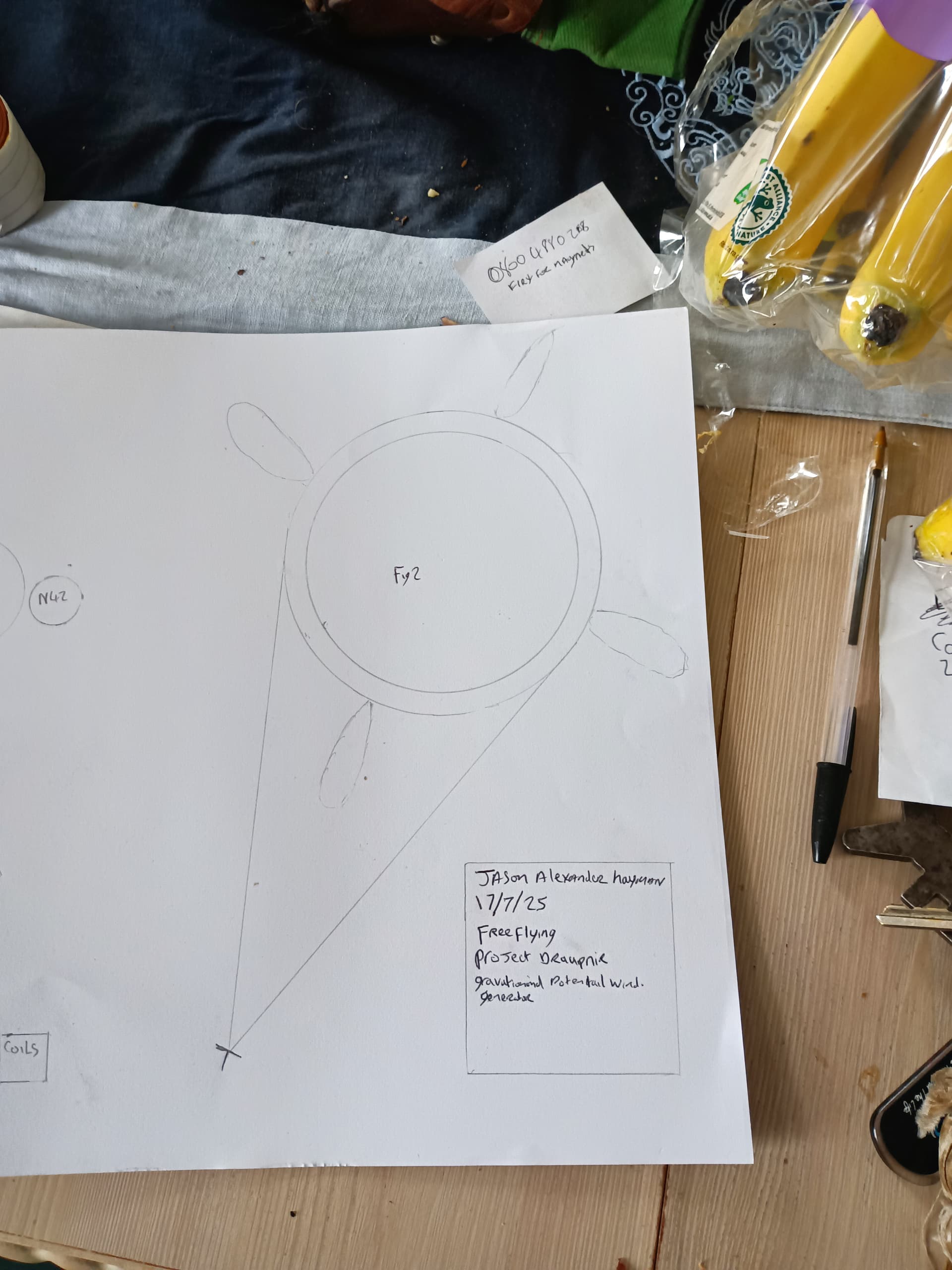
It is like an annular electromagnet generator. But for awes, it uses wind power to turn the rotor. Where you have a rotary kite system which the generator is attached to. The magnets fall under the weight of gravity opposite to the spin of the kite in the tubing. Which the generator is attached to. The magnets should be able to pass through the coils because of the rotation of the kites used. The wind will lift and spin the rotor. Enabling the magnets to fall through the tube under the power of gravity. That’s what generates the power. It dual action motion under every action has an equal and opposite reaction. The rotor is aligned with the direction of the wind in one axis. It turns round a central axis as the wind blows. That then allows the magnets to fall through the tube. Ideally the magnets will always fall to the lowest point around the rotor as it turns. Both coils and tube will be rotated. The magnets are free to fall while the tube and coils rotate in flight. Instead of wave action, you have wind acting on the rotor making it spin. I wish I could explain it better? Something like a daisy kite, rotary parachute, a spinning Jenny is what I have in mind for the generator. Like in the drawing below. Both soft wing and ridged wing kites can be used in the design. Hence why I think it could bolt into many a project on here. Hope this helps give you a better idea of what I was aiming for?
1 Like
Thank you Jason. I now remember that you had already investigated this route, as reported in the forum here.
It looks to be a mix of the Annular Electromagnetic Generator for Harvesting Ocean Wave Energy and the gravity device to compress air as shown on the video below (already in a previous discussion):
")
Pr. Seamus Garvey envisaged such a device for very large scales, allowing the weights to fall:

In a similar way, I expect your gravity device could better work at large scales. Perhaps you could replace the central annular generator with (for four blades) two tubes, each tube connecting two opposite blades, and including a coil at each respective end, and a magnet. The magnet falls from the top coil towards the coil at the bottom, at full speed, just like the weight falling in Garvey’s device. Now you would have a generator running in fits and starts, which may not be a very good thing. The annular generator as you envisage is surely better, and corresponds to the concept of the Annular Electromagnetic Generator, the difference being a regular rotation rather than the motion of waves.
2 Likes
Hi Jason,
Rod’s design isn’t that different from a regular wind turbine. The big difference is that he uses blades that are suspended between the lifter kite and the nacelle with tethers, instead of the blades being fixed to the nacelle.
So that means that he can use a relatively standard generator that will probably work fine. He should do that as that is the cheapest and least risky thing to do.
This is more or less the case for every AWES where the (heavy) generator is on the ground.
You are using permanent magnets, not electromagnets.
I guess the idea is that the ring with coils turns and that the magnets inside sit on the bottom.
But the ring should stay static instead. That ring would be fixed to the nacelle of the wind turbine. The magnets should move inside it, or the magnets should be attached to another, rotating, ring. The movement between the magnets and the coils then generates an electric current in the coils. If you rotate the ring instead, you’d have to think about how to move the electricity generated to the ground, probably involving slip rings, friction, and losses.
You can do tests just with a straight tube that you drop the magnets down. How much voltage and amperage do you get when you drop the magnets down the tube? You can angle the tube from vertical to horizontal to get the magnets to go at different speeds. You can also see if the magnets stick together and get stuck inside the tube.
Now you can only extract the potential energy from the very light magnets slowly falling through the very inefficient generator, so I don’t expect you can generate much electricity, or slow the wind turbine down much. A more standard stator and rotor design would be better. Then you can use the torque of the turning blades.

In the video: 1) (mechanical) rotation by hands; 2) rotation with magnetic field produced by electric current.
1 Like
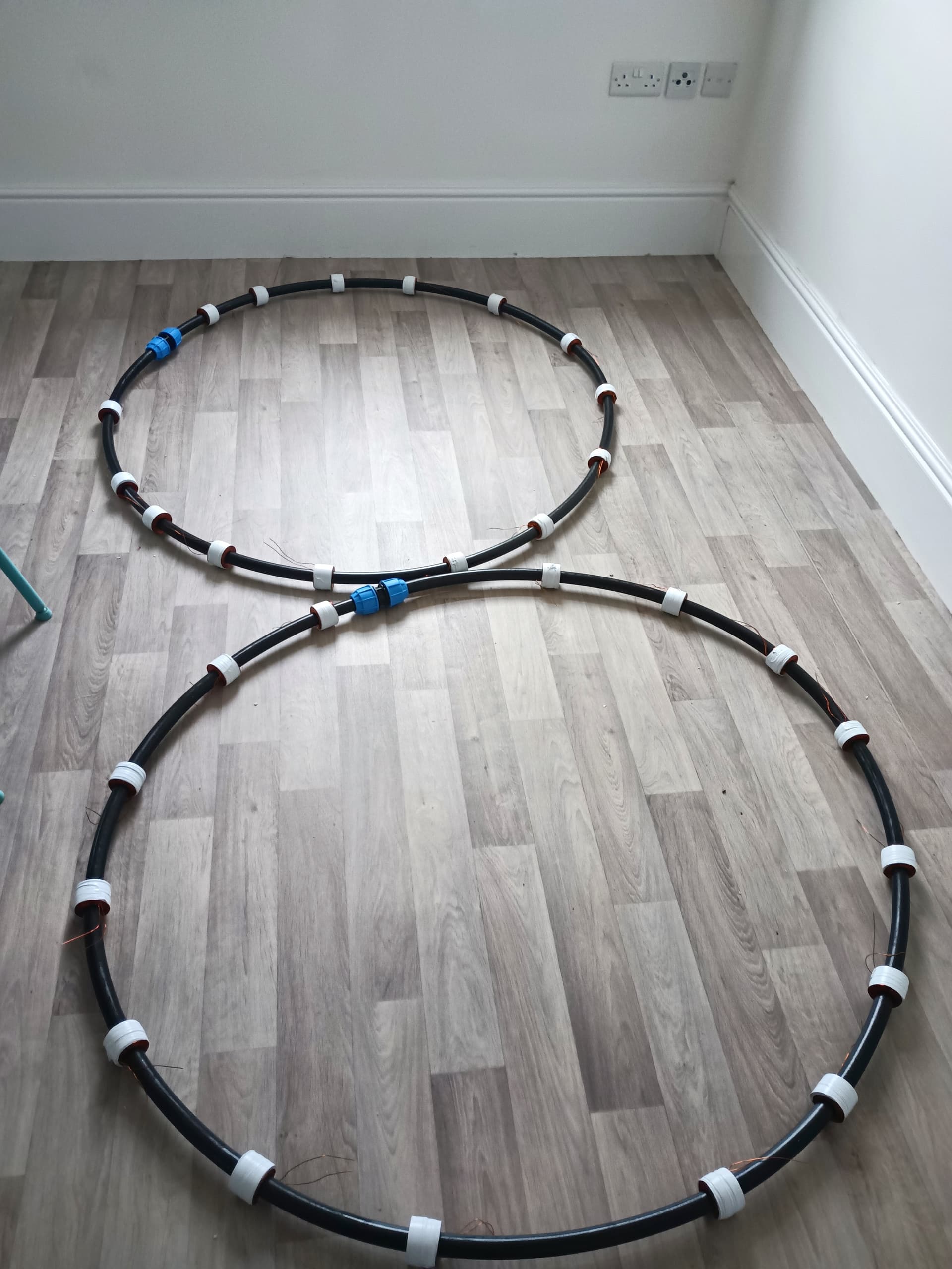
As luck would have it I do have an off cut of tubing and a spare coil. Which I could test the suggestions out on? Already tested to see if magnets get stuck in the tubing. Lucky for me they don’t as the i.d bore of the pipe is 20mm and have 19mm magnets. I had fears of the magnets getting stuck in the coupler. If I remember correctly the harder you pass a magnet through a coil the greater the voltage? Without a moving rotor it would be hard to gauge exact numbers? I can arrange the magnets in groupings of nsn,or sns which usually makes groups of three. So plenty of room to play with arrangements. For testing purposes.
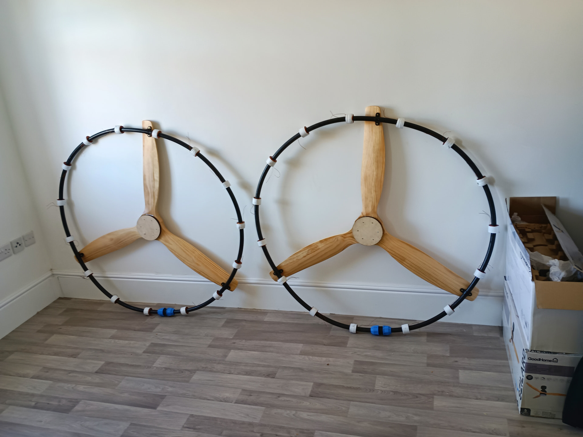
definitely a few interesting suggestions to consider. Did I mention I have two annular generators in the works? cost will be split between them for testing. So far this is near the £500 mark per unit as a sub assembly. I was hoping that the faster the ring spins the more energy it would create? Currently thinking of having a 4 bladed propeller style design. with the propeller blades used as central supports inside the ring preventing the whole thing collapsing. I could then play about with variable pitch? That should augment rotational speed and make it far more controllable. There loads I could do here it knowing where to start first? There is also potential to pre charge the coils to get better results? Turning it into a magnetic accelerator. The more magnets I have the higher the frequency of conductive events. Meaning more stable power output. That was my thinking on it? I was thinking the rings could be stacked in a kite train to generate more power? More rings =more power. Obviously there’s a cost to stacking them up. Still would be cheaper that a multi million pounds conventional wind turbine at this stage.
Total get how standard stator would be cheaper in some instances. That’s fair doos. I’m aiming for direct transmission of energy without the need for other components. It’s also a bit of a DIY projects for myself. Where the challenge is to make a generator with as many off the shelf items as I can for as cheap as I can.
Huge learning curve for me. I had the coils custom made by a company in Gloucestershire UK. the magnets were source online. So tried to keep things local to my region. Not an easy task. It’s why I’m going to have to outsource some of the work. If anyone is willing or interested enough to help? I know I have plenty of decisions to make but I’m ok with that. I’ve not much else to do. its fun trying to find what I need at a hardware store.
Umbilicals will need something like a swivel/slew bearings. though I’m yet to find a design for that. I do however believe it could be made frictionless perhaps even containing a spark gap/ induction gap? Honestly loads that could be done?
I’m trying to make it more like Meccano as I built it? That should people the greatest accessibility to my design? Which should make it user friendly? With low maintenance in mind. Anyways if you have any more input? I’m all ears. I’m happy to tube test for now just so I know my coil ratings. Also should give me an idea of optimal angle for the magnets to drop.
Very nice Pierre B, the idea is not lost on me. I suspect I could do something similar for my generator? Maybe exciting the coils first? Would be interesting to see how it would work in an AWES? Like The world’s most efficient motor is an ABB large synchronous electric motor that achieved an efficiency rating of 99.13% in May 2025 for a steel plant in India. I wonder how close my design could come to a synchronous motor if setup like an electromagnetic accelerator?
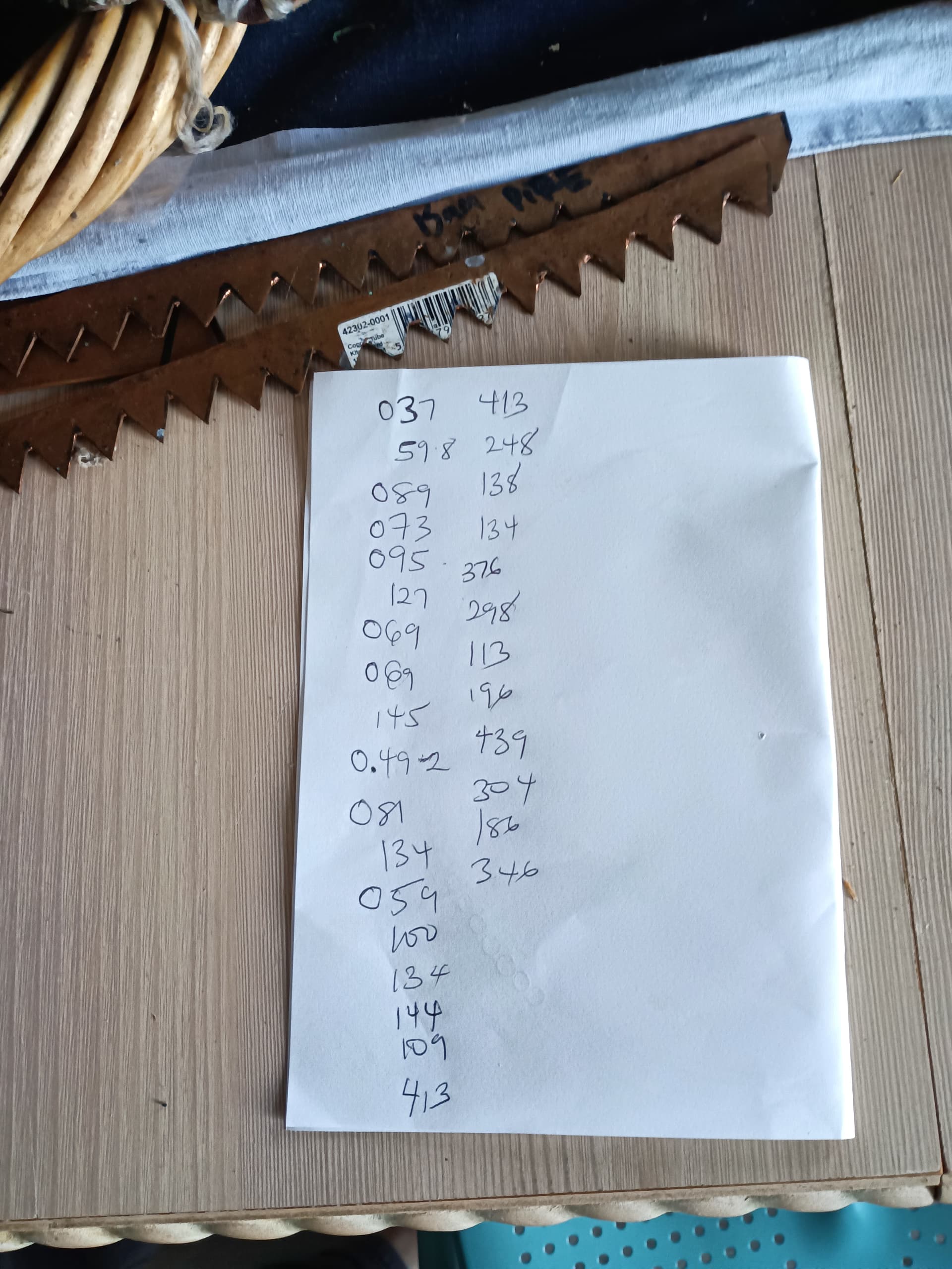
Ok just a quick run down volts per coil with the 19mm n42 neodymium magnets. the results after 30 vertical drops. My highest reading was 0.492v my lowest reading was 0.037v. score card below. Should give you some idea of the numbers for the generator? did seam the faster they dropped the greater the voltage. Though not on the score card I did manage to get 0.5v from the coil. This was using all 20 magnets like a magnetic bracelet/chain. Well worth doing as I have a better idea of power output potential. Results for using an un-energised. Very rough numbers but you get the idea.
Hi Jason. Always good to hear about whatever you are up to. OK so you’re working on a new generator concept. In the world of inventing, one main approach in explaining ideas is to identify what is lacking in the prior art, then explain how your new or novel concept solves that (those) problem(s). That approach nails down the “improvement” in the context or format of “problem => solution”. ![]()
1 Like
Hi Doug, interesting suggestions you have made. So how does my design best other design? Well I am aiming to be a low carbon alternative. Hopefully providing zero emissions power, provided I can get the voltage up per coil? Easy to resource materials with a low waiting time on delivery. So far on this section of the build I’ve spent about 3 months. Due to manufacturing methods. Coils being a large part of the delays. ordered 21/7/2025 arrived early September about six weeks after the order. Understandably since I suggested the idea it been about 2 1/2 years or so as health got in the way somewhat. But I’m back up for another round to take a crack at it. I’m also trying to use the least materials possible with a lower kg rating for final product. So light that you could put it in the back of a van? It should be entirely renewable. Which I believe my generator will be come final assembly? It should be easier to recycle come the end of its life span. So far as I know most of the material I’m using can be recycled in various processes. So overall a cleaner and greener product. It can be produced locally so fewer road mile are needed to produce the final product. I source most of my materials for the UK markets. At this stage it still rather cheap to produce I have two ring with coils, magnets, tubing for under£1500. I know that a diesel generator once set a local growing allotment back about 7k. I’m still cheaper by a country mile if you go by that standard? I’m Cost accessable by locally resourcing, which should make me more competitive in the long run? My design should be more durable than most other designs? able to take a hammering in a variety of conditions? From low winds to gale force winds. I suspect it would work better in a gale then anywhere else? Especially if a use variable pitch rotor system attached to the ring nacelles to control rotation. Usable in current designs as a sub assembly. Anyway just a few areas where my generator might be able to complete in AWES? I’m sure there’s more in just yet to figure that out? Please do chime in if I’ve missed something at this stage? Always willing to learn and take some critical advice. I hope to solve many problems with this project? It may not be the only way to go about it? but for me its a start and that what counts. Next step soldering and circuitry. I might just have a guy for that? Till then have a good day people. I will be back with more development as and when I get to them. Freeflying out!
Hi Jason: I always find your posts very interesting. Well, since you asked, the first problem I see here is whether the mere weight of the magnets provides enough force to generate much voltage or power. Most wind generators these days operate at hundreds of Volts, not fractions of a Volt. One of the biggest challenges, normally, is to affix the magnets to the rotor in a sufficiently strong way to prevent them being torn away by the immense magnetic fields produced by interaction with the stator. It is these very strong forces that generate strong electric power. These forces go way way beyond 1G x magnet weight. Also, a key factor to achieve a 20-year life is eliminating friction and wear. This might weigh against magnets sliding inside tubes, as that would entail wear. What I was originally saying was you might explain your idea as “The problem with existing generators is X, which is solved by Concept Y, because of effect Z”. As it is. I’m not sure I even fully comprehend your apparatus, or its intended role in a wind energy system. Hope that helps!
Let’s do a little simple math, OK?
1 Horsepower = 550 foot-pounds per second = 745.7 Watts.
So if you have a magnet weighing 1 ounce, falling at one foot per second, divide 745 Watts by 16 ounces to the pound, then by 550 lbs. I’m getting 0.0847 Watts, which somewhat agrees with the paltry voltage figures you’ve so kindly provided. Now, you could multiply that feeble output by 5, if the magnet were falling at 5 feet per second, and still be well under one half of a Watt. Then further multiply by, say, 8 magnets simultaneously falling, and you’re still at only 3.3 Watts. So I’m not sure how this ring with falling magnets could be useful enough to rationalize its cost. Actually, I have no idea how it could even be used at all, but maybe I’m just not seeing it.
Let’s remember our basic forces: The strong nuclear force, then the weak nuclear force, then electromagnetic forces, THEN gravity, which is the weakest of the basic forces. Funny to think that AWE seeks to overcome this weakest of forces, when a simple rigid pole will do the trick. ![]()
1 Like
Hi Doug, from what you’re saying I don’t even have a glorified mobile phone charger. I’m very intrigued with the suggestion of adding more magnets, The durability question, and the many of the other points raised in your previous post. I’m still up for the challenge just to see what I can get from my setup? 3 watts sounds like a challenge to beat? I am using 20 magnets at this stage. but I am willing to up the numbers if that will help get more watts? I did wonder if you had accounted for the rotation of generator in your calculations? As it’s gravity plus RPMS. Should make some difference in the numbers if not by much? I figured I could get about 15v. if I used both rings together in a kite train?
It maybe more but won’t know until I’ve tested it in the field? That should keep me busy for awhile? For now it’s just a proof of concept. I will be flying the generator soon as a get a kite to lift it skywards. Then I will report back here with the numbers. I think you might be right on the low power output? But as always see the project to the end. Even if that means it turns out it wasn’t a very good idea to begin with. It also means I got very bored enough to build a wild contraption. just to test the idea out in the field. At my current spending I’m looking at 2k all in. Just to find out how well it works? I’m doing it for fun. hopefully I can share some of that with the people of AWES all is good. Proof is in the pudding so to speak.
So I will get those real life numbers for sheer giggles at this point. It maybe that it won’t solve the problems I’d hope it to? There no harm in giving it a shot. Oh and thanks for chiming in it was very helpful insight. Like I said I will see this project to the end and get the numbers. Currently the bet is 3 watts. If it exceeds that I’d would be chuffed? Won’t know until I give it a go?
Hello Jason: Well, you could possibly add lead weights to the magnets to increase power. But that veers into “all-ya-gotta-do-is” territory, as in all ya gotta do is add heavy weights to a system that should be as light weight as possible. I must admit, I have zero understanding of the physical configuration you describe, nor exactly how it would or could work, but I DO remember one effort, which the person achieving it was quite proud of, that’, attached a self-winding watch to an unstable kite, that according to him, did serve to wind up the watch. Since this same person routinely predicts GigaWatts and TeraWatts from his ideas, imagining a larger version capable of useful levels of output might entail a LOT of extra weight. Overall, I’d tend to lean away from any idea that requires adding dead weight in any form to a system that is supposed to be supported by the wind. As one who builds generators, I do not thin the mere weight of magnets is going to be sufficient to generate much power in most cases. A tether is sufficient to provide any needed downforce, in most cases, I would guess. In engineering, it’s important to apply basic arithmetic to see what the actual possibilities might be. Anyway, with all your magnets and coils, certainly some powerful generator could be built! ![]()
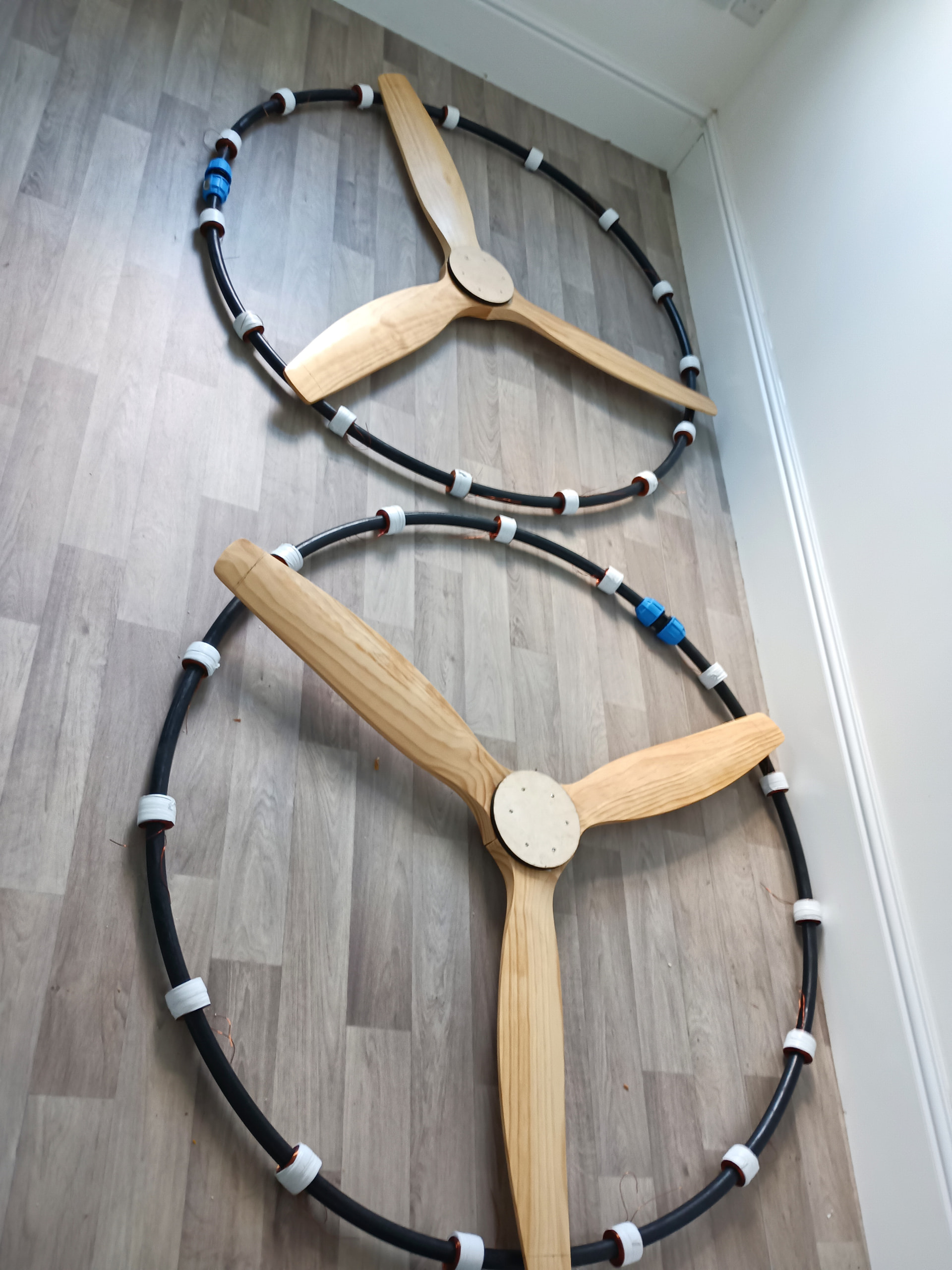
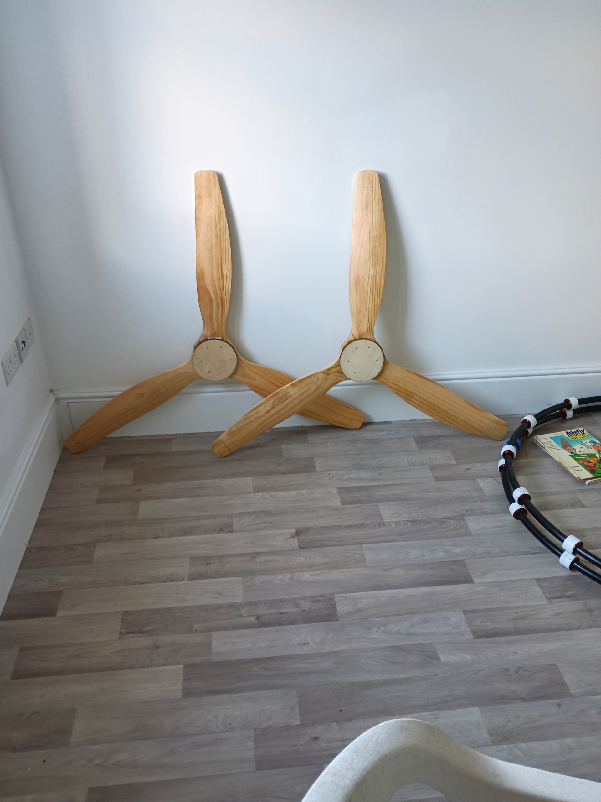
hi guy’s! I’ve just invested in some hard rotor blades to prop the annualar generator open and to allow it to spin. Still tons to do but I am making weekly progress. Not expecting much out of the project at this stage. I will report in once I have a video of it flying rigged to a kite. if you think I’m going wrong somewhere or perhaps problems I might run into, give me a shout? That should help me chart a course to a successful test flight? Currently going to use fixed pitch blades as that’s what I can get from DIY stores. Few more purchases and it will be flying come 2026. I also have some heavy duty swivels to add to the design. One at the top of the kite and one for the ground. Things are coming along and I hopefully will show you how far along I’ve got?
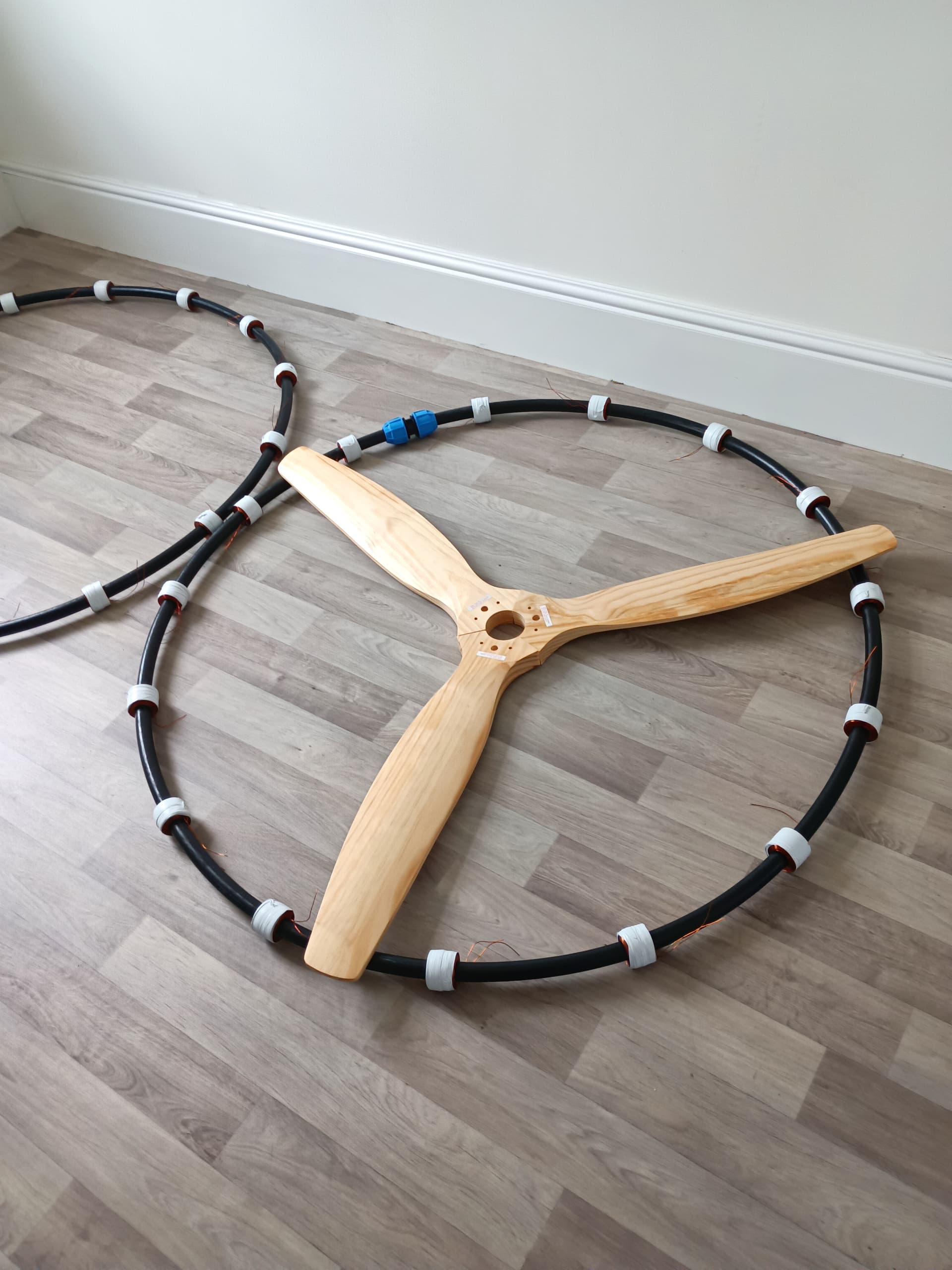

So I’ve been a little quiet lately have had some things done deal with. But I’ve just taken the next steps in my project. I’m one step closer to a flying prototype and proof of concept. Faceplates are on and connecting the turbine blades with coach bolts. I’ve also been talking to some other brains who reckon I might get 60% efficiency if I set it up right? I’ve even had guy from a green energy company say his bet was 10-15 watts. Stay tuned for updates as and when they drop?