Welcome to the forum @ChristophePochari1, and congratulations for this project which seems to be evolving towards possible solutions to harness high altitude winds.

Are you considering making a small prototype or proof of concept, to compare its behavior with that of an existing structure of smaller dimensions in the proportion of the claimed 350 m compared to the existing 200 m for the largest wind turbines?
Its hard to comment because knowing what the limitations of a modern mast/tower is is very detailed knowledge. So without that information it makes little sense to strt optimizing the design.
I would say guying wires is a well known technology but not used currently. Why? Why not make a tall steel tower with guying wires? Wouldnt that be a lot simpler?
Sorry cant help more unless these things re known. Most probably you will miss the boat unless you know exactly why the steel tower or steel plus wire tower is not a better choice than an inflated mast.
Hope it doesn’t get a leak.
Any failed seal or puncture results in catastrophic failure?
Guy wires, and even lattice towers, for utility-scale turbines, went out of style many years ago.
Visually unacceptable. Too busy.
Nice try, but like so many ideas, it incorporates too many new “all-ya-gotta-do-is” ideas to make it work. Looks like it requires a new type of elongated nacelle too.
As they say, “steel is cheap”.
Why the pistons? Will the turbine bounce up and down? What about temperature changes affecting air pressure? Wouldn’t it need a compressor anyway? Wouldn’t that be more effective than pistons, with possibly leaking seals?
Nice thinking out of the box, but seems pretty whacky to me.
Just a guess here: no experience in wind energy, right? ![]()
Giant wind turbines are discussed on 15 MW Vestas wind turbine over 900 feet (300 m) tall topic.
The world's most powerful wind turbine reaches 15 MW for the first time :
At 919 feet (280 meters), it’s also the world’s tallest wind turbine.
The giant machine, unveiled by the Chinese OEM today (Friday), boasts a rotor diameter above 280 metres and 66,000m2 swept area, said Mingyang as it joined compatriot CSSC Haizhuang at the 18MW mark and suggested there is more to come.
We are no longer very far from 350 m, and with classic tubular constructions for which we would have doubted that they could reach such dimensions. And it’s not over.
The future of harnessing high altitude winds lies in these traditional wind turbines, whose dimensions are constantly increasing.
Hi Pierre: And if you watch the video, it promotes turbines way, way, smaller than any current utility-scale offerings, yet mounted on these extremely tall inflated steel guyed towers. The promoter says there’s no disadvantage to using many more tiny turbines in lieu of a few larger ones. But what I’m hearing is a thick forest of towers, with crisscrossing, mutually overlapping guy-wires, with the towers way too expensive, even using thinner steel, for the teeny turbines floating on a piston, way up there on top. I can’t see how that would pencil out or be accepted, as a start, but if built, the layer of turbines would be missing the top-to-bottom height of larger turbines, greatly diminishing the swept area.
He’s also advocating installation of his proposed small blades using helicopters, saying it will only take an hour per turbine. Then again, if you need 1000 turbines instead of just 30 turbines… each turbine requires attention, maintenance, and operational supervision. More turbines = more permits, more cabling for interconnection, more towers of course, more people needed to maintain and operate them, etc., etc., etc. And making blades from steel. I’ve thought the same thing, but only for really small turbines.
None of these armchair inventors seems to think such basic things through. Windfarms are routinely “repowered”, meaning they remove the small turbines, and replace them with much larger turbines.
Dabiri is another example here. Fixated on this theme of “biomimicry”, he never explains why he would use vertical-axis turbines in the first place, given their dismal track record, other than it mimics some biological example of beneficial interaction between two turbines. But if the V-A turbines suck so bad to start with, they will still be worse than regular turbines. The next thing Dabiri never explains is why, when windfarms are “repowered” with larger turbines, they don’t just leave the old, smaller turbines in place, to add to the overall output. Does Dabiri think nobody ever thought of that? I think he is running on the fumes of enjoying special consideration for political-correctness from multiple angles, while not actually contributing to the art in any way. That article by Mike Barnard was answered by Dabiri in the comments where Dabiri mentions “a lot of snake oil out there” in the crazy world of whacky-wind-energy. Seems to me he offers a shining example of snake oil in wind energy. BTW, few people mention that our entire world is now powered by snake oil…
Anyway, one thing I will say is this guy came to the right place for his idea - “land of the lost” - and his idea IS “airborne” since the turbine floats on cylinder supported on a cushion of compressed air.
Funny, but just the other day, I was thinking of how amazing the idea of inflated tires for cars and trucks, vehicles in general, really is. Every vehicle out there is actually riding “on a cushion of air”. Joe Faust of the old forum might say cars “are actually” hovercraft. By the way, Joe told me the other day he is 80. Or was it 81? Holy cow, the years sure do go by, don’t they? Way back in the 1970’s, I bought a hang glider after reading an article in Popular Science or Popular Mechanics about hang gliding, mentioning Joe Faust publishing a hang-gliding magazine called “Low and Slow”. I didn’t know Joe way back then, but figured if hang-gliding had its own magazine, it must be for real!
Anyway, while the promoter of the inflated steel towers does seem to have quite a few tidbits of wind energy statistics at his fingertips, to me, the idea he is promoting seems insufficiently thought through. I will say though, any new idea could lead somewhere, even if not practical as initially presented. It might be a catalyst for someone else to have a further new idea for example. Or it might be improved by the original promoter, or someone else… ![]()
1 Like
This is one of the reasons why @ChristophePochari1 's approach deserves to be considered in an AWE forum, particularly if it would allow large quantities of materials to be saved in the initial version or further variants to come.
First of all, I say this discussion is most welcome in this forum.
I say the guying has some things in common with KiteX windmill
You could maybe try to figure out if the tower height is limited by not having guying or maybe there are other reasons why current windmills are not higher. Then also do a comparative cost analysis of your design vs current trends. Then do a mass analysis. Simple steps to increase your understanding of the problem.
I don’t want to take away your motivation. But from me the gut feeling is thumbs down. But you should make up your own opinion. I havent done near enough analysis to have a good opinion.
Hello Tallak:
I’m not seeing any similarity between the inflated steel towers with a turbine floating on a piston at the top, and the Kite-X turbine. But I DID happen across a whacked-out video about it on Youtube:
(1) Kitex CEO: Showcases Electrostorm Rotor - YouTube
For years now, so many videos on Youtube are just clickbait, with nothing meaningful to say, often showing stock footage of piles of hundred-dollar bills and generic lab techs wearing white coats and safety glasses, generic “business people” sitting around conference tables, etc. The “narrator” is apparently AI, using recorded voices, because they always get pronunciations wrong and emphasize the wrong words in sentences.
It says KiteX got the idea from kite-surfing, but never explained how a kite has anything to do with a fair-weather turbine on a short, temporary tower. The AI computer also said something about having sold, what was it, 1800 turbines? Or did they mean the price was 1800 Euros? Not sure if KiteX had anything to do with that mistargeted clickbait video being produced, but it is way off target and has nothing factual to say. The only thing I noticed is their footage of it running shows the shaft wobbling a lot. Maybe I noticed it more since, with my short attention span, I need to run videos at 1.5x speed.
Anyway, back to the video of the inflated tower, I will say, for one thing, Makani had a patent on a SuperTurbine™ with an inflated tower/driveshaft. Copycats. But the wind resistance of such a fat, lightweight tower, would interfere with rotor performance and tend to be blown to a horizontal position along the ground. Still, just goes to show, all roads lead to SuperTurbine at some point… (Oh no, he said it again!) ![]()
To resume, in the top of the tube (tower) a “sliding piston” under pressure tensions the guy cables by pushing them.
I don’t know if this would be sufficient for a heavy wind turbine, but perhaps far smaller unities could be used, for example in forests, in order to lift the basis of some AWES, in the way of @floba’s Crosswind Kite Power with Tower.
Only in that both deviate from
the norm by using guying and then moving the blades away from the guying wires. I’m sure Kite-X would consider going high altitude if the design would allow it (and the relevant resources to do this existed)
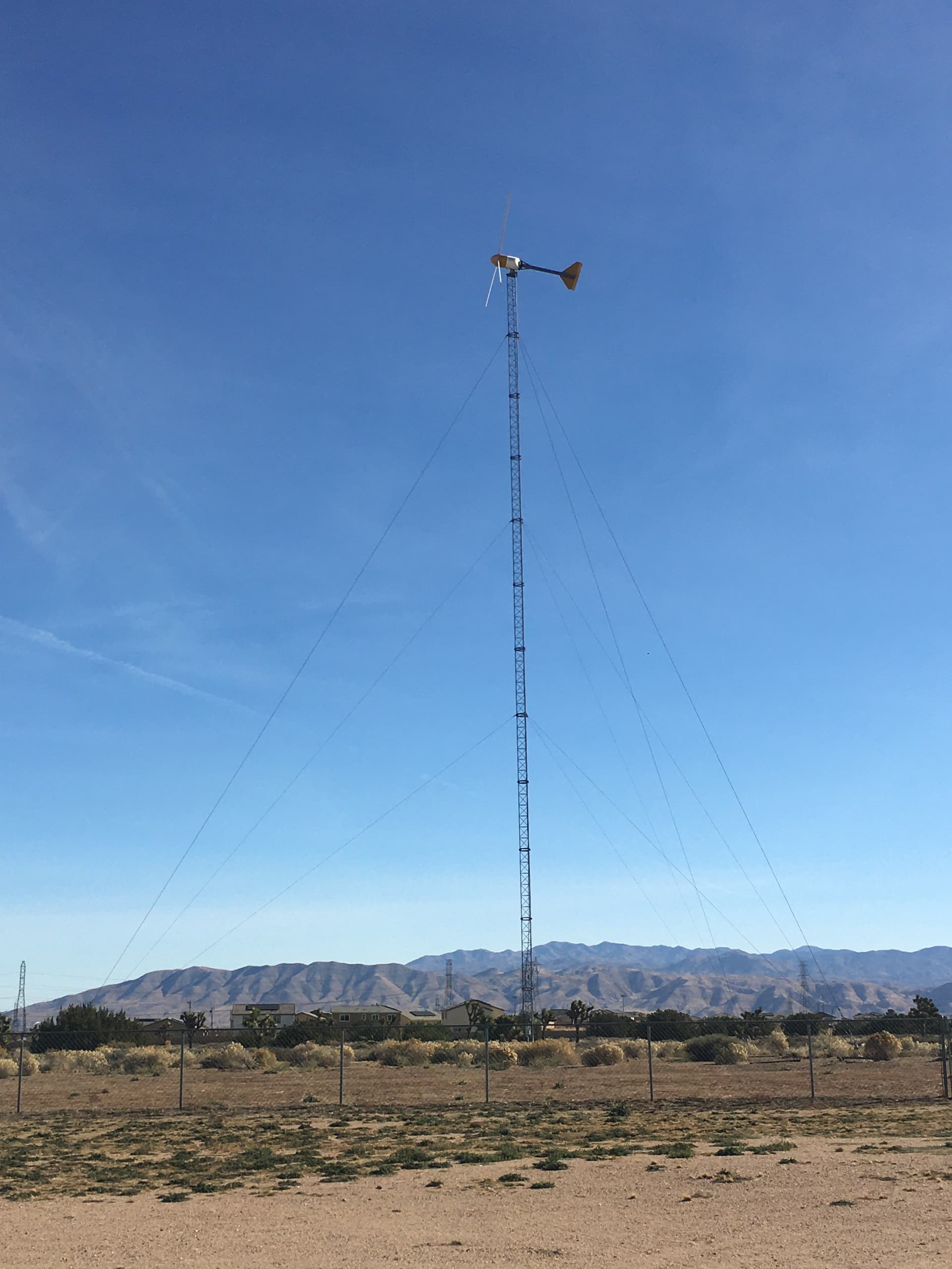
OK here’s a photo I just went out and took, of the 10 kW turbine out back, powering this message.
Note the 120-foot steel lattice tower with 3 levels of steel guy wires. And everything is arranged so the blades don’t hit the guy wires or tower. So all that is 100% normal. We have maybe 150 of these installations in my area. My SuperTwins of course avoid the blades being anywhere near the tower, since the driveshafts project outward, fore-and-aft.
I like the kiteX design, including the forward pole with guy wires, an old idea from Denmark I think it was - we’ve discussed it before - Gedser?.
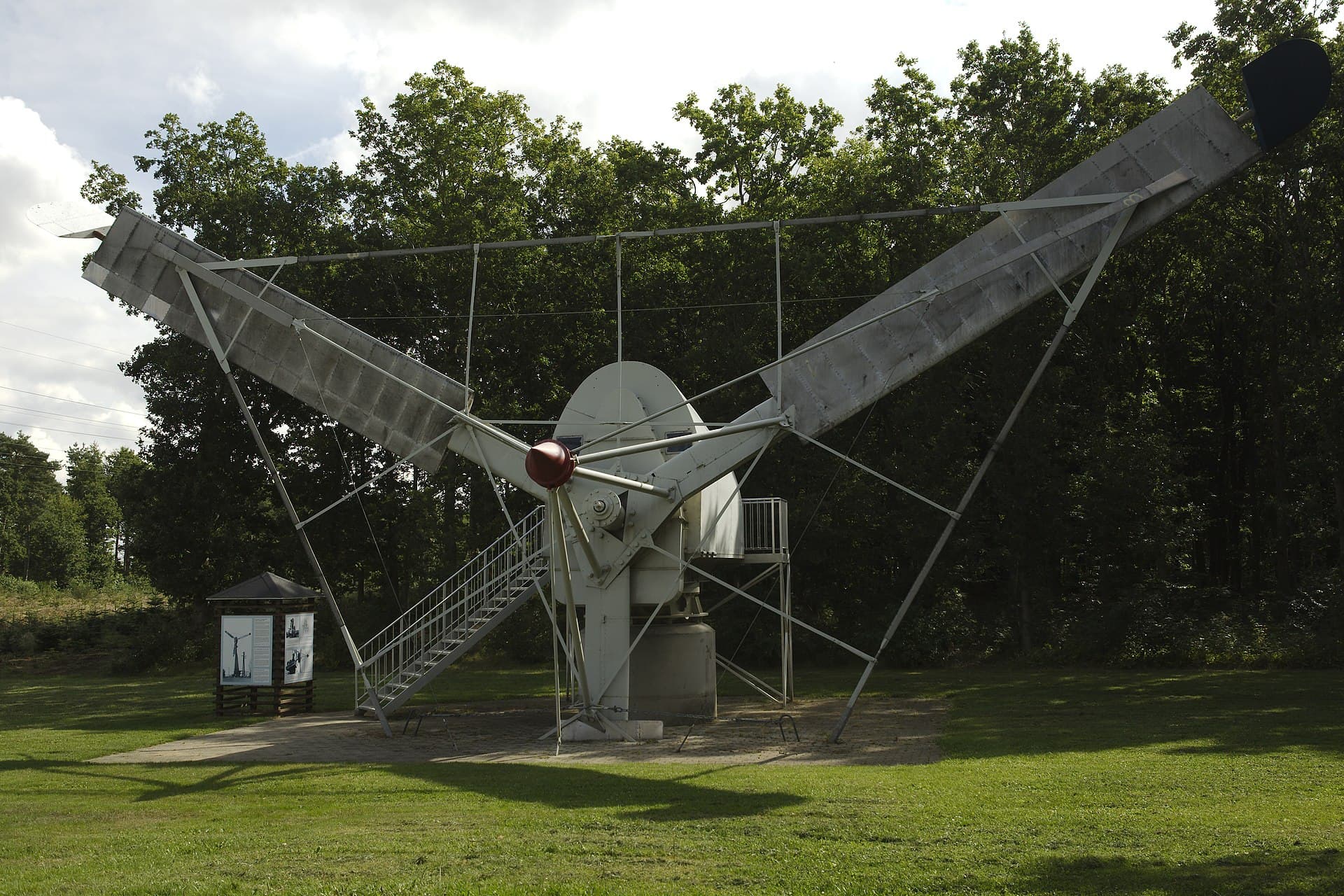
For whatever reason, it’s one more “new” old idea, that was somehow bypassed or discarded in the past. Anyway, my experience tells me that a kite-X turbine on high tower in a strong wind resource might not last even a day. Maybe not even an hour. A minute? Especially if the wind really started blowing. Those are the conditions when you find out what the problems are.
Anyway, I was trying to imagine why they ever stopped using guy wires at utility scale for wind turbine towers. I’ve come up with a few:
- Safety - trucks and cranes are driving around all the time. Do they want to hit a guy wire and bring down a turbine?
- Sabotage: Anyone with a wrench can undo a bolt and bring the whole thing down in a minute. Or a cutting torch… Or bolt cutters…
- Visual appearance: Windfarms suffer from visual clutter as it is - guy wires might be seen as more clutter. A big part of getting projects approved is making nearby residents and even passersby happy with the appearance. Tubular towers have a cleaner look than lattice or probably guyed tubular towers.
As far as what I heard listening to the video, the towers seem way too tall for smaller turbines, and you’d need too many towers, no matter how cheap. The guy wires would overlap and cross-cross, and, really, we’re seeing so many combined new ideas, or old ideas presented as new, it becomes quite a confusion to me. Maybe I need to watch the video again, cuz I was doing something else when it was on and only caught a few tidbits.
1 Like
So browsing through a paper on tower dimensioning like this one:
https://www.researchgate.net/publication/272492311_Design_Issues_of_Wind_Turbine_Towers
…I dont recognize your arguments as something they are very concerned with. So that is reason to think twice.
I have a question for @ChristophePochari1: Say you took just a normal tower, made the diameter larger and thinner walls. Then inflated to whatever pressure you think right; now would that tower be more resistant to buckling than the tower not pressurized? Is the guying wire a necessary component to the idea?
1 Like
This is exactly what I mean about this being too many ideas combined. The first question might be whether one could pressurize an existing tower for any reason. Then if that could allow thinner walls. Larger diameter? That could be a problem with wind interference, especially with a smaller turbine on a big tower as stated in the video.
Remaining questions are similar to why they don’t use guyed towers: Too risky. In either case, there are many possible failure modes. A tower dependent on remaining pressurized for its inherent strength sounds like an accident waiting to happen. One of those “what could possibly go wrong” moments… ![]()
2 Likes
Haha. I wasn’t aware of this story about us, good find ![]() didn’t have the patience to watch it all either.
didn’t have the patience to watch it all either.
1 Like
Thanks for your contribution.
As some of the others have indicated.
- is it necessary for the design to work to have a piston at the top?
- isn’t it possible to make it airtight enough that it would only need to be refilled every now and then? (Perhaps 5 years intervals, When you service the turbine anyway)
- couldn’t you design it such that the you don’t have to adjust the pressure when it’s cold and warm?
I think you can afford to transfer the loads from the intermediate guy cables to the tower section directly. The cables along the tower seems unnecessary.
3 Likes
I didn’t find it - it found me! ![]()
I think the “free floating piston” allows to modify the height of the tower, hence the guy cable tension adjustment.
Indeed using pressure to achieve the guy cable tension is too risky. If the tension drops for one reason or another, the whole thing collapses.
I would have a suggestion as an armchair inventor. ![]() We remove the guy cables. We take a normal tower. We use the “free floating piston” or something similar using pressure, but only to tension the rope drive transmission belt (Kiwee-like) to get the generator to the ground.
We remove the guy cables. We take a normal tower. We use the “free floating piston” or something similar using pressure, but only to tension the rope drive transmission belt (Kiwee-like) to get the generator to the ground.
We also remove the piston or something similar using pressure. The belt is tightened with a tensioner on the ground.
And then finally we realize that it doesn’t work as well as a traditional wind turbine, so we go back to the current art.
Access to servicing up inside the tower and nacelle are my main concern
Maybe you could keep this simple with existing roll stock tube materials
if like a palm tree (actually grass) you braced the outer skin with multiple pressurised pipes bonded to the inside of the existing outer skin
Sounds like a lot more material for 1 tower …
But I like the pneumatic support concept
Yet again the risk assessment impact of having to work near mechanically loaded high pressure tubes will take a lot of proof before it can be realised
Cool lateral thinking though @ChristophePochari1