I think Dave is saying you can stack taller near the centre…
Not exactly like any of these drawings… but feel free to expand…with reference to…
I think Dave is saying you can stack taller near the centre…
Not exactly like any of these drawings… but feel free to expand…with reference to…
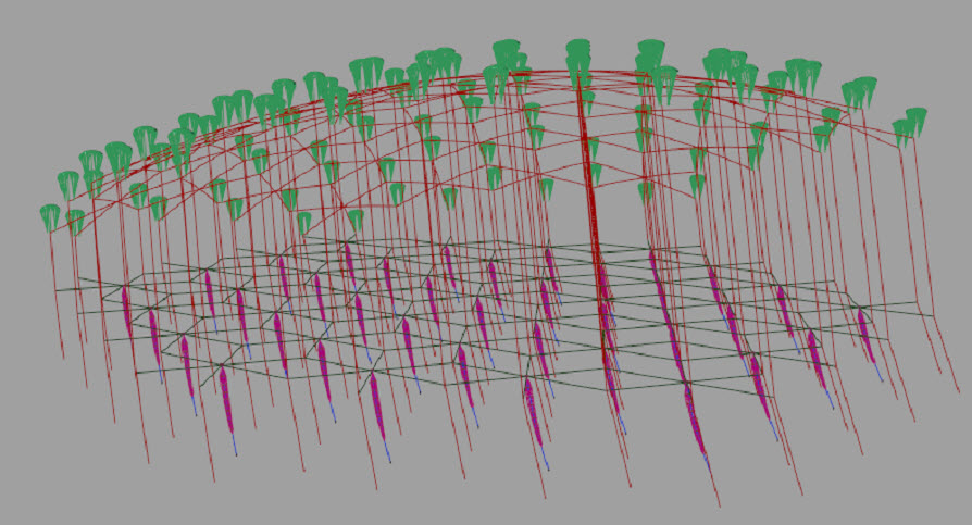
Is there a lifting kite at the top of each cell? Or where is the “lenticular mesh lifting layer”?.
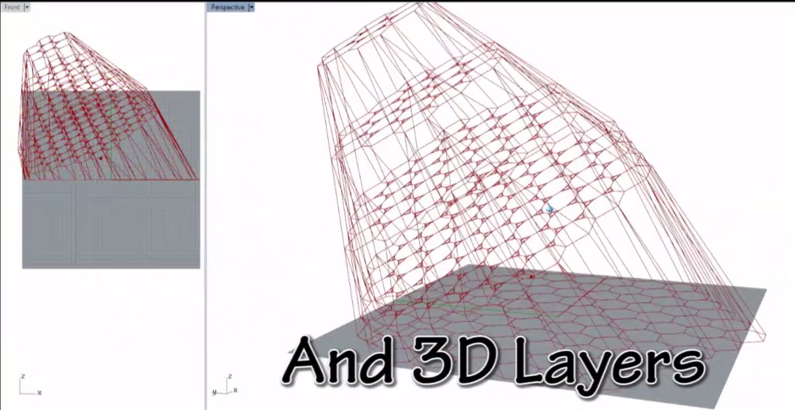
There are countless variations possible, and only a few known. KiteLab documented many lifter mesh concepts on the Old Forum. Rod has also covered many variations. Pierre could cut his lenticular tarp kite into a mesh of sub-sails, and it would fly.
There is theoretic advantage for different altitudes of lenticular harvest and lifter units, either by a higher center, or the whole lenticular network tilted up (AoA > 0) downwind. This seems the best way so far to host the most low-radius-loop units within a tight airspace and land footprint.
Again, a lot of early dense-network/low-radius-loop analysis is preserved in Old Forum archives, for those researchers to whom these ideas may be new.
Please use links or photos for actual transferable data comunications. We are humans not future all knowing bots with time to trawl through a massive ill ordered mess of old style online comms. (By which I’m referring (in the old sense without a link) to the old forum archives)
Rod,
Pierre seems to have missed extended lifter mesh discussion over the years.
Thanks for the graphic above. We honor reference requests as best we can. Its just not humanly possible to provide every request as fast as demanded. It helps to at least state that there are sources known to exist in the public archives, that others can help find as well.
If only the AWEurope’s secretive ventures were so helpful with requested information. They make lots of claims with no public accountability.
Today I made some experiments and measures with the same 0.7 m² kite (Peter Lynn, Vibe) with its two lines of 20 m. This kite was used on Low radius loop. This time two electronic steelyards were used. The previous measures were confirmed. The wind speed was 5-8 m/s, at the best the traction was 8-9 kg with loops of 3-4 m diameter, in such a way that I was pulled forward; with large figures in eight the traction was 4.5 kg on each steelyards, so 9 kg in the whole, in such a way that I was pulled in a side then in the other side alternatively. Then with a wind-speed of 3-6 m/s I made small (10 m) figures in eight getting a similar traction, which dropped when the figures became very small (6 m), as for the loops below 3 m diameter.
As a result the low radius loop looks to be efficient thanks to being in the center of the flight window, optimizing the swept area more than other figures such like even small figures in eight that use more wideness. Perhaps also the repeated circular figure leads to an increasing traction as this appeared. So the small loop could advantageously be used for pumping mode, perhaps also for a flygen, allowing more scaling for a given tether length.
Great to hear about active testing, Pierre.
kPower experience with looping foils under pilot kites also confirms “low radius loop” effectiveness. Adding the pilot kite establishes basic stability without active automation. 100% COTS TRL9 parts-
Example-
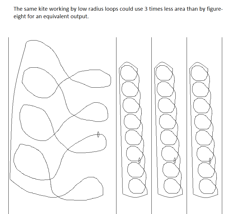
For the same kite and for an equivalent (and far more regular) power a low radius loop would allow a corridor more than three times less wide than for an eight-figure path, allowing a more dense kite-farm. A lesser flight speed is compensated by a work in a zone that is closer to the center of the flight window. A swivel would be required, unless the sense of rotation changes at each cycle, which would also allow a better distributed wear of the rotary wing, by alternating a higher speed in respect to its two tip chords.
I think an implementation of @gianni 's RotoKite could fly a pattern similar, similar use of space (maybe even slightly better) to the one you show here @PierreB
Where you depict a single kite pulling low radius loops for Yo-Yo phased extraction… Multiple Kites could easily be coordinated and set to perform that manoeuvre.
A Kite Turbine rotor has similar proportions to the the wing and loop you depict.
Assuming your Low Radius loop kites are bound together rather Like Daisy Kite Turbines, but just set on a single line to spin and pull like a phased pumping kite. (This is what Moritz Diehl assumed I was doing first time he saw a Daisy Kite Turbine… So it must be good. )
This has already been done
Our old kite turbines have been adapted in the past to fly on a single line
It would not take a lot of actuation to coordinate phased operation of multiple sets of these turbines .
The whole system may even benefit from a multi-line or coaxial pulled line where counter-rotary sets avoid imparting twist to the pulled line.
My low radius loop kite does the same than a purely rotary kite, by using less material, only one wing, not inner parts connecting blades or kites which can be problematic for scaling, so roughly the same material used for eight-figure crosswind kite, perhaps a simplified automation management, but not as simple as for a rotary kite. Moreover it is possible to change the diameter of the loops according to the circumstances.
The low radius loops (about 3.6 m diameter) of the 0.7 m² and 1.20 m span kite were realized in passive mode, by pulling on one of the two lines and keeping the position. The traction was strong (about 40 N with 4 m/s wind speed) while the loops gradually (about 1 m/s) descended.
These last days I tried to keep the altitude of the same kite by active manual steering, pulling (to rotate) and pushing (to ascend) the same handle, or alternating with both handles, which is the same. As a result rotation was a little broken at each loop, and the traction was far lesser, at least with a low wind, less with a strong wind.
I don’t still know the behavior of a large kite in the same comparative conditions (passive loops while descending, controlled loops while keeping or increasing altitude).
Today I experimented loops with another kite, being about 1.3 m², so twice the area of the original kite, and a flat span of 1.8 m instead of 1.2 m.
The behavior was very different: the loop diameter generating a strong traction had to be proportionately much larger, 5 to 6 m at least. And, with large or low radius loops, the kite descended much faster, despite a slightly more favorable surface-to-weight ratio.
I don’t know yet whether to deduce that we would lose any real advantage (same power by flying in low radius loop, passively descending, hence a better power / space ratio and an easier control?) with a largely scaled wing.
Still tests today with the same wing of 1.3 m², more in-depth because I no longer had the sun in my eyes. I added the fact of walking in the direction of the wind to represent the reel-out yo-yo phase, without noticing any particular difference except by a decrease in the expected traction.
The preceding observations are confirmed while being qualified by the following observations.
The kite seemed to descend more slowly with small loops generating little traction. But I cannot give a valid reason, having observed different things in the descents of the initial kite according to the tests, and sometimes no descent (because of a thermal lift?).
The initial kite was a Peter Lynn Vibe of 0.6 or 0.7 m² and 120 cm wingspan flat. Loops of 3 m in diameter should correspond to loops of 4.5 m in diameter for the kite of 1.3 m² and 180 cm wingspan flat which is an Ozone 1.5. As the Ozone lines are only 18 m instead of the 25 m for the Vibe, the larger kite (Ozone) was also closer. So there may be some error in my assessment: after all 4.5 m is not that far from the 5 or 6 m that I indicated previously.
And even if the loop is 5 or 6 m in diameter it is still narrower than a small figure of eight.
What I like about the loop, apart from saving space (without being huge), is the regularity of traction. In fact, the kite remains equidistant from the point of traction in the raised center of the flight window, unlike what happens with a figure of eight.
All this remains to be roughed up and tested with kites of different sizes and aerodynamic characteristics, and different winds.
Today I experimented an old 2-line kite of 3.75 m² and 4 m span, wind 5 to 10 m / s. Operation was correct despite wear, still pulling strong at the zenith.
Loops were about 3 to 4 wingspans (12 - 16 m diameter). At the end of two loops the kite was already largely lowered. So I think I can say that the passive descent while turning is not a good solution because the kite goes down too fast. A swash plate in @someAWE_cb style for control could perhaps be adapted, or something simpler and a swivel.
I continued the tests until I had to let go of a handle because of the pull too high for me (and for one of the two bridle knots that went off) during a loop, and comparable to that which resulted of a long trajectory as achieved in a figure eight.
Page 12, from the table 2:
Flexible wing Lift-to-drag ratio 6
Rigid wing Lift-to-drag ratio 20
On this table, the Max flight circle radius is about 5 wingspans for both rigid and flexible wings. I think things are perhaps different. Also take into account the tether drag.
https://www.skybrary.aero/index.php/Radius_of_Turn :
Radius of turn is dependent on both airspeed and bank angle. The radius of turn at any given bank angle is directly proportional to the square of the airspeed. Doubling the airspeed results in a radius of turn that is four times greater while tripling the airspeed would result in a radius that is nine times greater. Conversely, if the aircraft speed remains constant, increasing the bank angle will decrease the turn radius.
As a first approximation the turning radius of a rigid wing will be higher not directly because of its higher mass, but due to its higher speed resulting from higher L/D ratio. The same when comparing flexible wings with different L/D ratios. So a good efficiency could result from an accurate balancing between a high enough L/D ratio, but not too high in order to keep a tight turning radius and gain some space.
Kite turbines kinda break the rules here
The bank angle of the blade on a kite turbine (outer tip down to ground station) would promote the opposite turn - out of the loop. The tethering between blades keeps the loop tight (tensile and size)
Yesterday I experimented the same old 2-line kite of 3.75 m² and 4 m span, wind speed being 5 m/s. As the wind was constant during some minutes and not to high (for me), not too low, the experiments were more precise, although not measured. 4 wingspan loops were required for an optimal traction, more or less being equivalent of what I obtained by using large figure-eight paths.
Picture page - Kitemill (pictures 13 and 15): loops are used.
I think that loops provide more regular power because the wing is always at the same distant of the middle of the flight window. But I don’t think we would save much space by using loops. Indeed the spacing between the units is necessary even if the loops are tight. And by using figure-eight paths, the second loop of one unit could match the first loop of the next unit, even more with large paths.
Just sensational work.
I’d like to fall back on this older thread which quite relevant, I have reviewed some studies graciously provided by this group.
In @Florian Bauer’s PhD dissertation from TU Munich, he mentioned that the ideal tether inclination and length, along with the most efficient altitude for kite systems, may not be as large or as high as previously thought. It seems that we could benefit from focusing less on issues like tether weight and drag, and instead, concentrate on designing more efficient, low-altitude kite systems.
One aspect that caught my attention in the dissertation was the comparison between loops and figure 8’s. @Florian Bauer suggested that the Makani systems, which use circular paths, require a complex hardware setup to prevent tether twisting. He also mentioned that figure 8’s might be a preferable option, considering their relative simplicity and the avoidance of potential patent issues.
However, one area I felt could have been explored further was a more in-depth analysis of the pros and cons of loops vs figure 8’s.
Looking at the discussions in the AWES Forum, particularly on @PierreB’s “Low Radius Loop” thread, it was interesting to see how the community is experimenting and learning together. @tallakt made a noteworthy point regarding line twisting and suggested that alternating loop directions could be a potential solution.
The results from @PierreB’s experiments with low radius loops were quite thought-provoking. The experiments showed that these loops could potentially allow for larger kites and produce smoother forces. Yet, the point that tight loops might not necessarily save as much space as initially thought does raise some interesting questions.
Also, @kitefreak’s positive experience with low radius loops further solidifies the case for this approach.
This exploration into flight path mechanics is proving to be quite a learning journey. The discussions around tether weight, drag, optimal flight paths, and the impact of patents on the design choices are all significant considerations that will help guide the design and optimization of future AWES projects
Here is an example of how kite surfers are already paving the way, Triple loops.

We can see the measured traction (at 0:26), and also wind speed at the beginning of this now old video (2012) which is linked to some other comments including Low radius loop - #4 by PierreB.