Medium scales for torque transfer systems onshore and offshore

(NOTE: I edited this post after due to some calculation errors I made originally. I left some notes in italic writing, otherwise the text remains)

I wanted to make a stab at figuring out the scaling of the structures that keep the rotating turbine shaft at a certain diameter

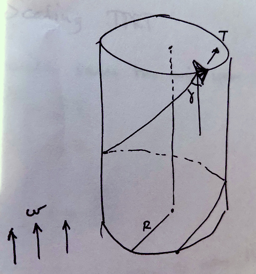
My thinking starts with a single kite, the wind blowing directly from below (I am not looking into the power generation much here). The tether is kept in shape on the outside of a cylinder shape by some unknown force (the fine grid of carbon fiber rods in practice, or some inflated structure).

This is a simplified structure for analysis.

What do we know? Well this is a drag mode AWE rig, so the angle \gamma is predetermined when running at optimal production (something like slowing down the kite one third). I won’t go into further details just here. The cylinder radius is R. The tether tension is constant T. The length of the tether is l. All of these are assumed to be constant.

The force required to keep the tether at a cylindrical shape may be calculated by splitting the tether into infinitesimal sections then using Newtons equations to calculate radial force balance. I found that:

\frac{d C}{d s} = \frac{T}{R} \sin^2{\gamma}

C is the sum of forces applied along the tether outwards from the center of rotation, the free variable s being along the tether length (also I am skipping how I came to this equation for brevity).

At this point we decide to scale the wingspan of the kite by a factor x. The produced power scales with the area of the wing, thus \tilde{P} = x^2 P (I am using tilde to mark the scaled power, and P without tilde for the non-scaled power). We will scale the whole rig also by x, leaving us with \tilde{R} = x R, \tilde{l} = x l, \tilde{T} = x^2 T.

\frac{d \tilde{C}}{d s} = x \frac{T}{R} \sin^2{\gamma}

Next we will assume that the structure keeping the rotary shaft at a certain diameter is built from carbon rods. We will maintain the same number of these structures (rings). As both the distance between rings and the tension of the tether has increased, the pressure that must be withheld is scaled by x^2 (one x for scaling of \frac{d \tilde{C}}{d s}, one x for scaling of the distance between the rings). Also the size of the rings themselves must increase by x.

To figure out the new thickness of the rods, we will consider the buckling load of the rods. The buckling load is given by

F = n \pi^2 \frac{E I}{L^2}

Having E as a constant dependent on rod material, L being the length of the rods, and I being the moment of inertia of the rod. As the rods are cylinders, I = \frac{1}{2} \pi \rho L r^4. r is the radius of the rod, \rho is the density of the rod material. Thus

F = \frac{n \pi^3 E \rho r^4}{2 L}

We’ll scale the radius of the rods by a factor \tilde{r} = y r. The length \tilde{L} = x L. Last, we need:

\tilde{F} = x^2 F

\frac{n \pi^3 E \rho y^4 r^4}{2 x L} = x^2 \frac{n \pi^3 E \rho r^4}{2 L}

y^4 = x^3

y = x^\frac{3}{4}

Thus the mass of each rod will scale by

\tilde{m} = (x L) \pi (y r)^2 = x^{2.5} m

We can conclude that the weight of the supporting structure will scale by scale to the power of 2.5. This is not really bad considering that the tether tension T (almost equal to the lift) scaled by a power of 2. We could set up an equation comparing the scaled and non-scaled ratio of support structure mass to tether tension:

\frac{\tilde{m}}{\tilde{T}} = x^{\frac{1}{2}} \frac{m}{T}

All in all looking like something that will probably not become a serious issue for a long [scaling-] time yet. NOTE: This conclusion is probably wrong. This is a serious scaling issue. The relative mass of the shaft increases by x^{\frac{1}{2}} which is not really a good thing

Now some final comments as to why rotating rigs will not go high-altitude withtou futher innovation: Compared to Yoyo, the whole tether is moving. This increases tether drag by a factor of 4. Next, you need to split the tether into n thinner tethers in order to get a geometry suitable for torsional transfer (assuming there are rings or other supports). This will increase the tether drag by \sqrt{n}. For n = 6 the increase in drag is by a factor of 2.44 compared to a single tether rig.

I’m not saying rotational is not worthwhile, I’m just saying that if it works, it probably will work at somewhat lower altitudes. Personally I still think this concept may be worthwhile. NOTE: Again, the conclusion is not as clear anymore

2 Likes

There is a world between the simplified and detailed analyses. As an example M. L. Loyd (Crosswind Kite Power) obtains 22 MW in his simplified analysis then 6.7 MW in the detailed analysis. Dynamic factors such like the sudden changes of wind forces and directions at different heights should be taken account as for their consequences on the structure. Structural shears would likely highly occur by wind variations, inducing pendulum moments on the rigid elements then a rapid destruction of the device. In practice, at only 1 kW power scale, the rigid rings have already buckled while I am not aware that the drag of the ropes would have stopped the device. A rotating AWES without rigid parts aloft for the torque transfer could allow to avoid the buckling issue.

My analysis only considers scaling effects of the shaft support structure. What I showed (and possibly there could be errors in there) is that you could scale a torsion based rig without a severe mass penalty.

I did not consider how heavy the unscaled support structure would be. But the scaled rig should be able to sustain similar wind shifts.

Though more accurate calculations are indeed possible and probably also useful for someone doing rotational torque AWE (TRPT) I dont think the numbers I found in the analysis are necessarily that bad. I think they are probably more precise than Loyd’s initial calculations on AWE.

Here are some examples why: Loyd did not consider tether drag, cosine losses or roll angle losses. Nor did he account for the force necessary to keep the kite afloat. These factors compound to reducing the efficiency of the kite rig. Loyd knew about these but they were not important to the principal operation of AWE.

For my calculations, we have some factors related to having a discrete number of support rings, so the pressure force C is not applied evenly. But even considering such issues, given geometric similarity og the scaled and unscaled rigs, these effects will not scale at all (meaning scaling has no effect positive or negative)

The factors you point out such as oscillations are not really relevant to the question of mass scalability of the shaft support structure. They could be analyzed separately.

I do admit though that torsional transfer without any rigid structure (no compression) sounds nice. The only problem is that you would be narrowing down the number of tools in your toolbox by «downselecting» these at an early stage (the term downselecting was meant humorous)

The way I scaled the rig (any distance scaled by the scaling factor), the kite will fly similarily when scaled, the only difference will be «cubic» mass scaling of the kite and the benefitial effects of the wind gradient (the former being the most inportant). Aerodynamically only the Reynolds number should be different. I did not consider the drag of the support structure, presumably scaling at x^{1.5}.

1 Like

Sorry. This analysis, and particularly the weight by scaling compared to the tether drag issues, is not confirmed by the facts, or, if you prefer, simulated data do not match measured data. Daisy’s rigid rings have already buckled, while I am not aware that the drag of the ropes would have stopped the device.

Although this topic is not particularly dedicated to Daisy, could you provide a numerical example, by taking a power of 1 kW and rigid rings mass of 1 kg. What would be the mass of the rigid rings as the power becomes 1 MW, keeping the proportions?

NOTE: This was written based on a calculation error previously, the conclusion is not clear with corrections I added. I have also updated the numbers based on the correction

I am just saying that if you could build a TRPT rig producing X kW, you could probably build a scaled up version, eg. 2 times the scale. The scaled up rig would produce 4X kW and work mostly the same as the smaller rig. The mass of the scaled up shaft would not be significantly larger than the mass of the original rig, relative to the new size.

My motto in these things will always be to build as small as possible at first, with a clear view of how the system could scale. It seems to me that @Rodread’s and @someAWE_cb’s rigs are a good starting point. If they can make them work at the current scale, they may be able to scale them.

Not that I am not saying they are scalable. I’m just saying that the mass of the rings should not become an issue for some time yet. The assumption here is that this mass is not already a critical factor to construct these rigs. If they are, it’s uphill from here on, because relative mass scaling of x^{\frac{1}{2}} is still slightly bad. For a scale of 2x as I started with, the relative added mass would be 41% more. For a 10x scale, the mass is 216% more.

For 1000x scale (my question was from 1 kW and 1 kg for the rigid rings to 1 MW and mass of the rigid rings?) I would obtain 562% more, so 5623 kg only for the rigid rings. It is the weight of five Makani’s M600 which would total 3 MW, not less. The tether drag issue would be likely lesser. I am sorry for your conclusions from your analysis.

Moreover we should add the pendulum moments on the rigid elements due to structural shear by wind changes as I mentioned. So the potential of scaling of TRPT torque transfer devices comprising rigid parts is low, very low. It was the reason why I conceived a rotating device without rigid parts.

Ok. Scaling from 1 kW to 1 MW would imply a scaling of area by 1000x. This again would imply scaling of wingspan by x = \sqrt{1000} = 32. The rigid wing’s mass would scale by somewhere between m = m_0 \cdot x^2 \approx 1000 \, m_0 and m = m_0 \cdot x^3 \approx 32000 \, m_0. This is besides the point though, and common to all AWE.

The mass of the shaft, according to my calculations, if the 1 kW shaft originally had a mass of M_0 kg would be:

M = x^{2.5} \approx 5800 \, M_0

The mass relative to tether tension would be

\frac{M}{T} = x^{\frac{1}{2}} \frac{M_0}{T_0} \approx 5.7 \frac{M_0}{T_0}

I realize now that I made a mistake here, So I have fixed the calculations in the previous posts. The consequence being that mass of the shaft is indeed something to look out for with large scale.

Thanks @PierreB for being inquisitive on this one. There may still be calculation errors I’m afraid…

1 Like

Given the new numbers I came up with, @Rodread and @someAWE_cb should probably decide on a scaling target, eg. 32x for a 1 MW rig as described in the previous post, then make the rings heavier by a factor of 6x without adding strength, to more accurately test the effect of a scaled TRPT shaft. Most probably, their current designs for rings are not optimized, so the problem may not be as big if you consider that a ring for a huge power plant would probably be optimized for lower weight.

Thanks also @tallakt as you made a fine and useful analysis, confirming in the end my initial concern about the huge scaling issue for torque transfer devices with rigid parts. An optimization of these design would lead to minor improvements. And it is still without taking account of pendulum moment leading to the increase of structural shears due to wind changes at different levels of the device.

1 Like

I think my point of view from earlier stands. TRPT with rigid structures is feasible and may scale, but the length of the shaft is probably limited.

Scaling huge will also impose some constraints on the size of the ground station. These rings must be handled and stored on ground. If they are collected at the generator at their native size (no collapsing), a 1 MW rig will presumably require a machine 100-200 meter diameter at least. This is in addition to the airspace use restrictions.

A similar winch for a Yoyo type of rig should be a lot smaller.

Though not a dealbreaker by itself, the cost implications of this should be taken into account.

Yes, I repeat it from years! It is the price to pay. But if we consider that the flying rotor should be as huge, the land use would be the same, the ground ring adding a permanent ring on the ground. And also said ground ring can help to expanse the rotating kite, helping takeoff.

I agree, and as a consequence that becomes a large ground ring rotor leading to the rotating reel system.

Yes, or for a similar ground rig size the yoyo kite can fly far higher. The rotating reel system is equal in its three dimensions, leading to the requirement of a huge basis to allow flying higher. But if the ground ring can be made cheaper, why not? For me alone I cannot tested it above 1 m. A team could made an exemplary of 10 m: it would work but of course would not be marketable.

So for a 1000x scale the mass would become astronomical. 5623 kg is already a far too high value for scaling to 1 MW, and this value could be yet higher.

No. I dont think 1000x scale of wingspan is relevant. 1000x scale of power and tension is 32x wingspan.

If you scale wingspan by 1000x you would scale a kW rig into a GW rig

I didn’t mention 1000x scale of wingspan but of power. 1000x scale of 1 kW leads to 1 MW.
And also:

I don’t know if you keep your version above as your calculations and versions often change. That becomes confuse.

My estimation is the same for a long time, as it is the reason why I conceived the rotating reel system, and is based on a simple observation: the rigid rings undergo the forces by a powerful system, leading to a significant weight penalty as the system scales, limiting the potential of scalability (likely far below 1 MW). Adding structural shear and pendulum moment I evoked. The experience has confirmed it (some rings have already buckled in a 1 kW-range device).

A TRPT without rigid parts can scale higher: it becomes the evidence itself. The price to pay is a larger ground ring.

For studying the dynamics of how torque waves ripple down a TRPT… Check out @Ollie 's awec2019.com presentation when it gets published.
Yes you have to be careful with loading up torque through a TRPT even if it has solid components. Way more careful for a similarly dimensioned TRPT without any rigidity

Pulsing torque waves enable high-velocity load-motion peaks at the PTO, if wanted. They could also be used for phase-changes aloft, directed from below.

Nah. They twist your tube into a mess if you’re braking too hard

“Braking too hard” is not the only option. A momentary release of load will also create a torque pulse, analogous to a “push-turn” in multi-line kites.

A useful phase change might be AoA modulation to drive the Daisy during lulls, or maybe for launching with lift from surface calm.

I am trying to recap.

This is matched by the quotes above and the quote below:

knowing that:

These assertions seem to be consistent with each other.

5800 or 5623 kg/MW (and without taking account of factors such like structural shear by different winds) is a crippling ratio, and any incremental improvement would look like to empty an ocean with a spoon. As a result the rigid elements of the compressive structure cannot scale much as I expected for years, trying to solve the problem by implementing a large horizontal ground ring leading to the rotating reel system. This system has be well studied but with only one rotor (figure 22.18 on https://www.researchgate.net/publication/324135034_Airborne_Wind_Energy_Conversion_Using_a_Rotating_Reel_System). Although I evoked the possibility of a stack of rotors in my patent (FR3034473A1 - Eolienne aeroportee rotative - Google Patents) I think that a single rotor is easier to maneuver by automation.

Though you probably have some good arguments, you should not be extrapolating on such a poor foundation. Before extrapolating do some proper engineering to find the minimum weight for the scaled down design, before scaling up on paper.

I find keeping stuff afloat costs relatively little compared to generated power. Mass is difficult to deal with, but to a certain extent its not a showstopper.

This being said, the design from your patent does fit the bill for a TRPT (?) with usefulness not due to high altitude, rather just a possibly more cost effective design.