Now you see your own analysis as “a poor foundation”.
I do not need to extrapolate to understand the flaws of a system at first glance, having spotted from the start (the design of the rotating system reel being the proof of it) that the driveshafts with bars or rings looked like rather to disjointed pythons. But I recognize that not everyone has this faculty.
This favorable result is explained by a small scale of experiments. The prediction of scaling laws is severe limits as mass grows faster than size, and power-to-mass diminishes to “showstopper” value.
Its vital that almost all AWES mass aloft work at direct harvest of kinetic energy, not parasitic secondary functions.
Even a fifth of the weight would be a failure. @kitefreak just provided you an explain:
And we speak about a compressive structure with rigid elements. And as I mentioned several times such a structure would be subject to oscillations by different winds. Rings have already buckled at about 1 kW. That cannot work at utility-scale.
Last time the TRPT overtwisted, I reckon (the video shows) it was the undamped mass of the ground station around the anchor axis which caused misalignment after the generator ramped current too fast. That was up on the hill at Swordale. Smooth Westerly.
I can’t think I’ve ever noticed a gusty misalignment being much of an issue on a flown system. Even during mast mount tests… Although they’re kinda pre stretched.
The doomy predictions are like saying that the Internet won’t ever be realised after having seen the world’s first transistor burn up.
This is not an explanation rather an opinion. And an opinion that has been stated enough times that I am aware of it’s existence. But - the opinion is not substantiated, and it is not even true in general. This is at least my opinion on that opinion.
I would like to present a thought experiment to see how one could have more lightweight compressive rings.
We’ll start out by looking at the formula for buckling force:
F = \frac{n \pi^3 E \rho r^4}{2 L}
This is for a rod. I presume a tube would allow superior characteristics, but this is not important here.
We see that the buckling force F is inversely dependent on the length of the length of the rod L.
If we divide the length L into x supported pieces in series, while retaining F, we see that the radius r is reduced to \tilde{r} = \sqrt[4]{\frac{1}{x}} r. As the mass of all the pieces is dependent on r^2, the mass of all the pieces will be \tilde{m} = \sqrt{\frac{1}{x}} \, m
. If we divide the supporting rod into, say 4 pieces, The weight of the compressive structure is halved.
This structure could also be foldable and possibly easier to handle on ground. (I admit probably harder though).
My point is still that before identifying a “dead end”, do some proper preparation at small scale and then apply a scaling calculation. A windmill does not necessarily need to scale into infinity to be useful. Perhaps even a 100 kW AWE rotational windmill could be cheap enough to allow 30 of these to compete with a single huge HAWT.
@tallakt’s quote is called a sophism. My explanation is connected to different statements as formulated in this thread, comprising your own analysis you now disavow, comprising rotating reel contents, comprising the issue of the rigid parts used as compression structure, comprising @kitefreak’s quote above about a fundamental principle. So what you call an opinion by isolating a sentence is an element of a global thinking of which you do not guess any start. In the other hand I could agree that your opinion is only an opinion, as for your initially wrong conclusion for your analysis leading to my correction.
Now I’m going to get down to business, by studying projects that are worthwhile, including the rotating reel system.
Why not leave all these rings and bars to implement a rotating system with a possiby stack of rotors as soon as diametric dimensions allow, instead of stagnating for years on the same concept?
Good question @PierreB.
Oddly though the same data seems to give us diametrically opposite conclusions.
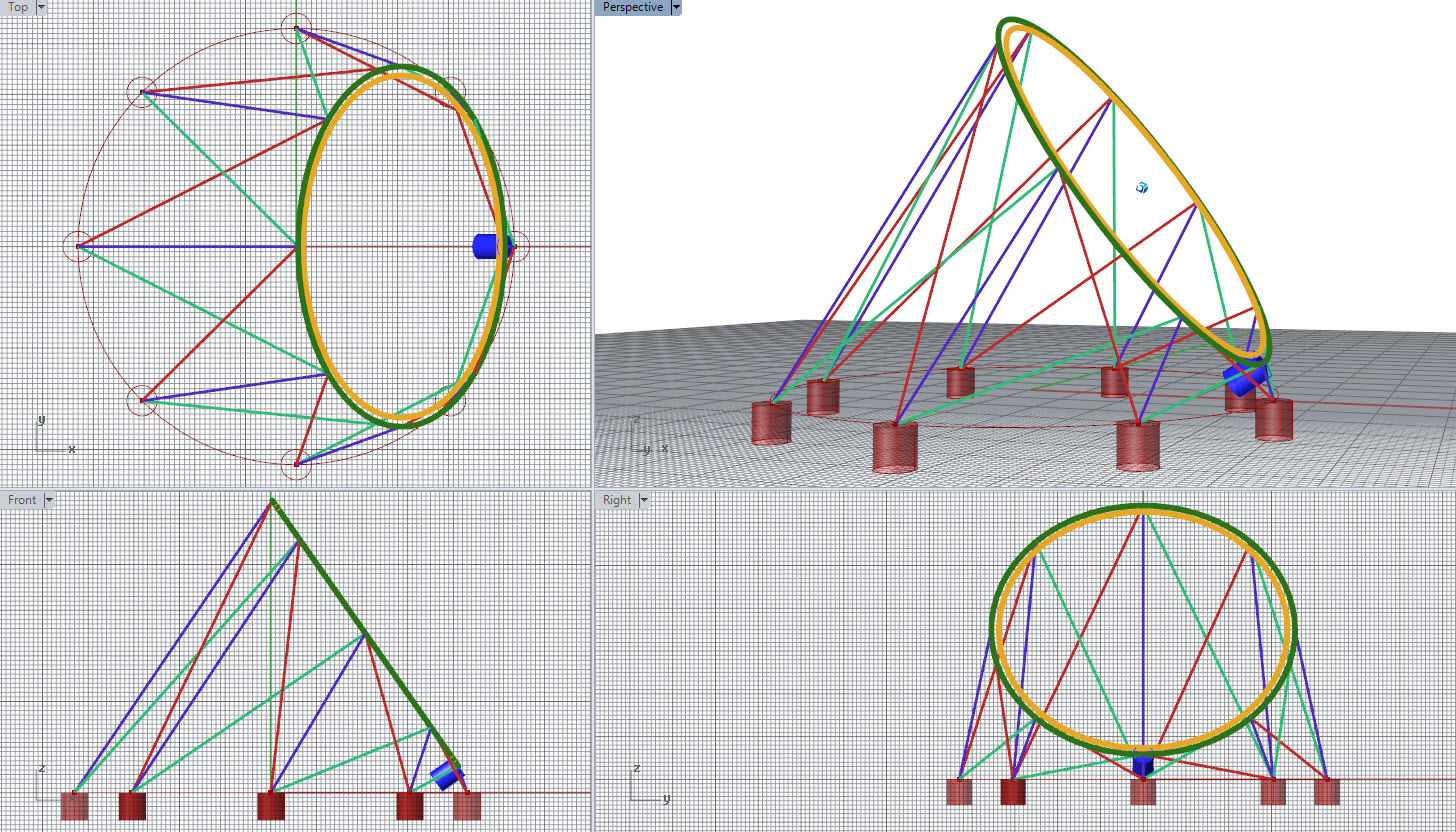
Consider the following ring as a ground station PTO.
The red, green and blue lines hold it to anchors and can be extended and retracted, (let’s say in much the same way as rotating reel tethers can) But let’s just use these lines to allow the ring to be lifted to height and hold the ring against the torque of generation (blue cylinder)
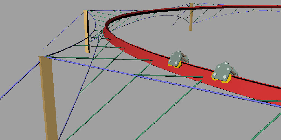
Back in Feb 2014 I was drawing the logic of ground rails which would use tensile material to support rotary actions of kite systems … such as this…
So on the first drawing, Maybe the green ring is rigid, The yellow one doesn’t have to be. Green, wouldn’t need to be too heavy as long as the 2nd moment of inertia is good. The green and yellow ring could be configured like this tensile rail in the second drawing. Where the yellow PTO ring (1st drawing) is a tensile carriage ring array of inwardly connected rail carriages inside the supporting ring (green ring 1st drawing)
Say at the height of the yellow as show already… there is a wing deployed which just clears the ground. These wings arrayed around the ring will be potentially very light.
So … that’s an easily hoistable PTO, aligned to the axis in working operation, which lays on the ground for take off and landing, is large scalable and can support stacks of wide lightweight self expanding rotors… What’s not to like there?
So now that’s shared @PierreB, are you interested in it at all? … Or do you genuinely not like it?
It’s a bad trial of intent that you are doing for the nth time.
I see it as a personal attack again.
And all the more so as it is an obvious (so unpatentable) idea that has already been discussed, and that I have discarded from the outset because of the crippling weight of the ring limiting the scalability. Why not just put a rotor on a windmill mast…
Putting trivial ideas into brilliant packages does not work.
I’m really impressed by engineers who retain the ability to juggle formulae after uni life. It’s an incredibly useful communication tool, and a skill I found hard to maintain after years of neglect. @tallakt I think you have super powers.
However, fundamental to this analysis…
The Length of the TRPT section doesn’t need to scale with the turbine.
It may even be, that the pure TRPT section can be removed altogether.
This suggests (certainly to me) it won’t be the deflection of beams between successive rotary lines which prevents lines compressing together… It will be the inflation of the turbine as a whole, derived from the aerodynamic of the set of blades around a ring, which prevents torsional compression.
Call it the AWE “pure wing” heuristic, that highest power-to-mass is achieved by the greatest proportion of working polymer in the tensile wing role. More than wishful opinion, the pure wing principle is seen in competitive power kite engineering; with no design mass allowance wasted on launching-landing system mass, no active sensing/computing/actuation mass, no rigid compressive structure impregnated with resin, and so on. All inherent failure modes of secondary mass dependence are avoided as well.
Pure wing is superior at any scale and wind velocity, and scales further than anything less.
The issue with pure wing is that it may not be possible to build them. That’s why one would want a toolbox with as many tools as possible, and then know about the compromises attached to each tool
The purest wing possible, we can agree. Logo graphics can be omitted, to save a few grams.
A good AWES Flyoff criteria would be a max-mass limit for designers to work within. Those teams who cannot design to the purest wing standard would have a fair chance to add other kinds of flying mass.
Formally, a relatively heavy kite has a higher zero-point energy to overcome for flight, with less free-energy available. That’s classic thermodynamics.
I did some back of the napkin calculations to compare a TRPT with Makani’s 5 MW design from the FAA application.
The Makani rig produces 5 MW for a wing weighing 10 ton and a tether weighing 3.6 ton. The wingspan is 65 meter. Tether is 1 km, looping radius is 265 m.
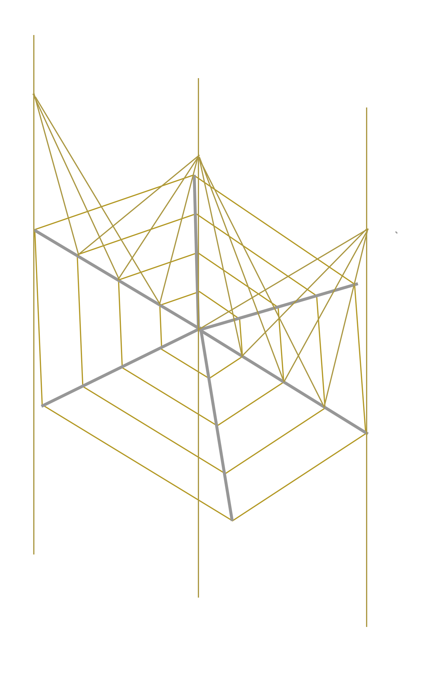
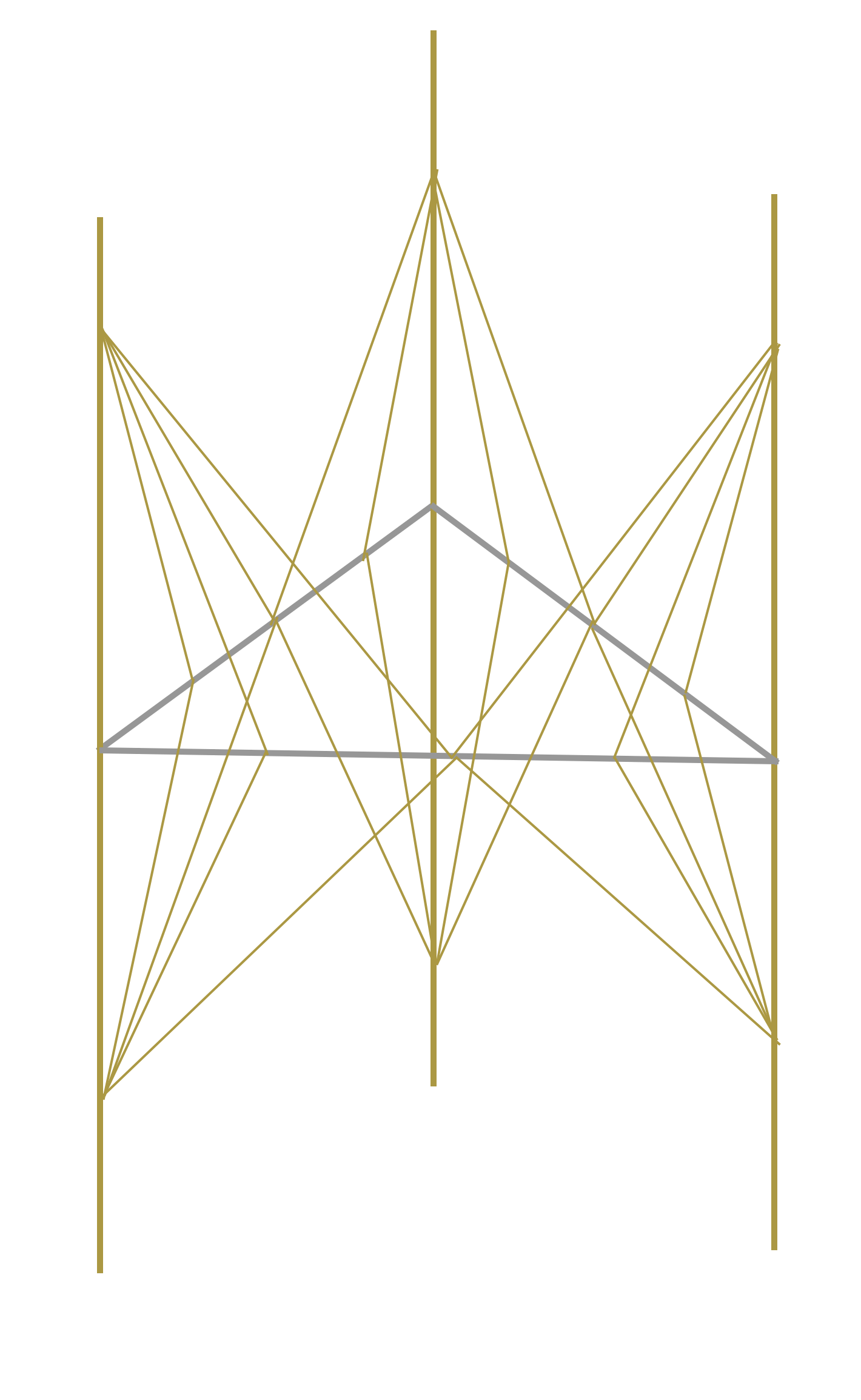
I suggest replacing this with a 6 kite TRPT, with carbon fiber spacers in the shaft. The six kites have wingspan 27 meter, and the flying radius is thus reduced to the equivalent looping radius 108 m. The shaft diameter is 72 meters (one third of the looping radius, a number chosen at whim). The spacers will be looking like “star of david”, and six of these spacers are deemed necessary to support the hollow shaft. 6 rods of approximately 60 meters are needed for each spacer assembly.
From the paper [2] we look at the optimum weight of the hollow spars for the supports. A value of \phi = 10 and \gamma = 18^{^o} is chosen (again on whim) and some calculations later (eq 17 in [2]) I arrive at a total weight of the spacers of 1360 kg. This is very small compared to the weight of Makani’s specified conductive tether.
Now if this is even close to correct, the TRPT is quite interesting because it does use a lot less airspace, is unaffected by gravity slowdown, requires less control input and still provides a way of energy transfer to the ground.
If more precise calculations were made, I would assume the tether length would have to be reduced to approximately 400 m for the TRPT to account for extra tether drag using six tethers rather than one.
Design of laminated composite cylindrical shells works under axial compression, as the title of the paper indicates. But AWES undergo numerous forces that interact. As a result the whole likely would dance rock-and-roll for a few minutes before collapsing, and that without applause.
The star of david configuration allows to connect each spar at four points for support. One could also add bridling. Though the spars are long, carbon fiber is an exceptional material. Im not sure this is not possible to scale quite far
Sadly, Google-Makani won’t publicly disclose why M5 development was cancelled, but its clear that scaling laws apply, and that open comparison of tested Wing7 and M600 power curves would show a severe loss of efficiency by that scale-up. Pierre is right about how a truly catastrophic crash would soon occur if they were so unwise to continue scaling blindly.
With a weight of six kites of 7 ton, the spacers would only weigh a fifth of the kites in this configuration. I dont see that oscillations are necessarily a big issue. The rings will be rotating slowly for such large rigs
Makani overlooked many scaling limits and failure modes only identified on the Old Forum. For example, a scaled-up M5-class motor-gen dissipates heat too slowly to run as hard as a power-to-mass equivalent smaller unit. It would burn out quickly if it tried to match power-to-mass performance of the smaller motor-gen.
There is generally greater VTOL settling-under-power risk with greater scale, that may have already killed the Norway M600 prototype.
Leading to a huge torque transfer, then a huge compression load. Would the generator even rotate? And also with a shaft of 72 m diameter the tilted generator should be held by a huge crutch, in the end like a tower for a current wind turbine.
 .
.